manuals.online logo
Brands
  1. Home
  2. •
  3. Brands
  4. •
  5. HASE Bikes
  6. •
  7. Bicycle Accessories
  8. •
  9. HASE Bikes 25874 User manual

HASE Bikes 25874 User manual

1
Trailer Option 11/18 DE-EN
www.hasebikes.com
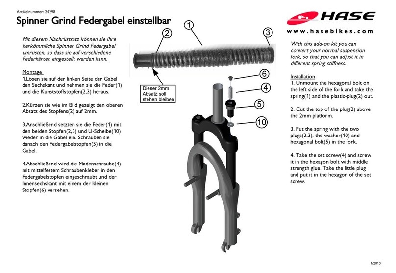
Trailer Set
Trailer option
#25874
Das Trailer Set ermöglicht es, das KETTWIESEL und
das TRIX wie einen Fahrradanhänger hinter ein nor-
males Fahrrad zu hängen.
Um Erwachsene gefahrlos transportieren zu können, verfügt
der Nachläufer über eine Auflaufbremse, die beim Bremsen
des Zugfahrrades automatisch das KETTWIESEL bremst.
Die Fahreigenschaften des Zugfahrrads werden nicht negativ
beeinflusst, da die Deichsel im Laufradmittelpunkt angreift.
Der Wendekreis für Linkskurven wird nicht eingschränkt, der
für Rechtskurven beträgt je nach Radgröße des Zugfahrrades
zwischen 4,50m und 5,59m.
Hinweis:
Die Montage der Auflaufbremse darf nur durch den
Fachhändler erfolgen.
Lesen Sie sich vor der Montage die Anleitung sorgfältig
durch.
Achtung!
Die beiliegende Weber Schwerlastkupplung hat eine ma-
ximale Zuglast von 100kg.
HASE BIKES gibt die Verwendung der Weber Schwerlast-
kupplung in Verbindung mit der HASE BIKES Deichsel für
eine höhere Stützlast als die von Weber maximal freige-
gebene Stützlast von 6,5kg frei.
Beachten Sie die beiliegende Anleitung der Weber Kup-
plung.
Unter 40Kg Zuglast ist auch die E-Kupplung zulässig.
Achtung!
Die Auflaufbremse kann nur an KettWieseln und TRIX
mit mechanischen Scheibenbremsen verwendet werden.
Achtung!
Eingeschränkter Wendekreis in Rechtskurven. Vor der
ersten Fahrt unbedingt den Wendekreis testen.
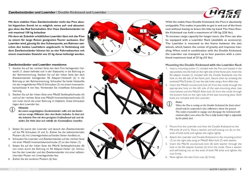
The trailer set makes it possible to hang the KETT-
WIESEL and the TRIX behind a normal bicycle like a
bicycle trailer.
In order to transport adult passengers safely, the Trailer is
equipped with an overrun brake that automatically brakes
the KETTWIESEL when the towing bicycle is braked
The trailer has no negative effect on the handling performan-
ce of the towing bicycle because the drawbar attaches to the
center of the wheel. The turning circle for left curves is not
affected. For right curves, the turning circle is reduced to bet-
ween 4.50 and 5.59 m (15-18 ft), depending on the wheel size
of the towing bicycle.
Note:
The assembly of the trailer must be done by your dealer.
Read the instructions carefully before assembling.
Caution!
The used Weber heavy-duty coupling has a maximum
load of 100Kg.
HASE BIKES allows the use of the Weber heavy duty cou-
pling in connection with the HASE BIKES drawbar for a
higher drawbar load than the maximum drawbar load
of 6.5 kg approved by Weber.
Refer tot he enclosed Weber coupling instructions.
For loads under 40 kg, the E-coupling can also be used.
Caution!
The overrun brake can only be used for KETTWIESELs
with mechanical disc brakes: not for hand-driven trikes
and not for the Lepus with steel frame.
Caution!
Limited turning circle in right turns. Be sure to test the
turning circle before the first trip.
2Trailer Option 11/18 DE-EN www.hasebikes.com
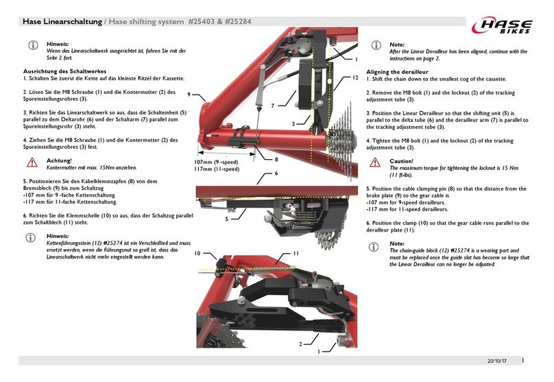
Auaufbremse montieren
Die Traileroption wird, in Fahrtrichtung gesehen, un-
ter das linke Spureinstellohr montiert.
1. Schrauben Sie den Adapterlock (1) mit den Di-
stanzhülsen (2) und den M6 Senkkopfschrauben
(3) in die beiden hinteren Gewinde an das Spu-
reinstellrohr.
2. Setzen Sie die M8 Distanzhülse (4) auf den Adape-
terblock. Montieren Sie die vormontierte Auflauf-
bremse mit der M8x40 Senkkopschraube (4), der
Unterlegscheibe (6) und der selbstsichernden M8
Mutter (7) an den Adapterblock.
Kugelgelenk am Lenker montieren
3. Lösen Sie die selbstsichernde M8 Mutter an der
Verschraubung der Lenkübertragungsstange und
ersetzen Sie diese durch die Kugelkopfmutter (8).
Den Torx Schraubenkopf erreichen sie durch die
obere Aussparung im Lenker (gelb markiert).
Achtung!
Vergewissern Sie sich, dass die Lenkübertra-
gungsstange richtig verschraubt ist.
Die M8 Schraube muss mindestens 8mm und ma-
ximal 11mm in der Kugelkopfmutter verschraubt
sein. Verwenden Sie hochfesten Schraubenkleber
und ziehen Sie die Schraube mit 21Nm fest.
Ist die Verschraubung nicht sicher, besteht Un-
fall- und Verletzungsgefahr.
Mounting the overrun brake
The trailer option is mounted under the left tube for
track adjustment when viewed in the driving direction.
1. Screw the base plate (1) with the bushings (2) and
the M6 countersunk bolts (3) into the two rear
threads on the tube for track adjustment.
2. Place the M8 bushing (4) on the base plate. Mount
the pre-assembled overrun brake to the base pla-
te by using the M8x40 countersunk head screw
(4), the washer (6) and the self-locking M8 nut (7).
Mounting the ball joint to the handlebar
3. Loosen the self-locking M8 nut of the steering rod
and replace it with the ball nut (8).
You can reach the Torx screw head through the
upper recess in the handlebar (yellow circle).
Caution!
Make sure the steering rod is screwed in prop-
erly.
The M8 bold connection must be at least 8mm
to 11mm screwed into the ball head nut, other-
wise the bold connection is not secure. In addi-
tion, the bold connection must be secured with a
high-strength loctite.
If the bold connection is not secure, there is a
risk of accident and injury!
7
6
4
5
8
1
2
3
3
Trailer Option 11/18 DE-EN
www.hasebikes.com
1
Assemble the mounting bracket
Mounting on foldable frame
4a. The mounting bracket (1) is attached to the M6 screw
connection of the folding axle. Loosen the screw and
place the bracket.
Use medium strength screw loctite.
Make sure that the retaining clip is screwed to the
retaining bracket as shown in the picture.
Note:
Since the bracket is attached to the folding axle, it
can be slightly twisted after the folding operation.
If you want to click in the brake rod you have to turn
the bracket back into the correct position.
Caution!
When folding the KETTWIESEL, the brake rod must
be released from the ball joint as well as from the
bracket and must pass the handlebar during the
folding process.
Mounting on non-foldable frame
4b. Position the mounting bracket (1) on the frame gus-
set as shown in the picture and mark the hole posi-
tions with a pen.
Drill the holes with a 5mm drill bit into the frame
gusset.
Screw the bracket firmly with the M5x12 Allen bolts
and self-locking nuts.
Note:
After assembly, the bracket must be bent into
position so that it does not collide with the over-
run brake when engaged.
2
3
Haltewinkel montieren
Montage am faltbaren Rahmen
4a. Der Hochbindewinkel (1) wird an der M6 Ver-
schraubung der Faltachse befestigt. Lösen Sie
Schraube und platzieren Sie den Hochbindewin-
kel ist.
Verwenden Sie mittelfesten Schraubenkleber.
Achten Sie darauf, dass der Halte-Clip wie im Bild
zu sehen am Hochbindewinkel angeschraubt ist.
Hinweis:
Da der Hochbindewinkel an der Faltachse be-
festigt ist kann er nach dem Faltvorgang et-
was verdreht sein.
Möchte man die Bremsstange einklicken muß
man vorher den Hochbindewinkel wieder in
die richtige Position drehen.
Achtung!
Beim Falten des KettWiesels muß die Bremsstan-
ge sowohl aus dem Kugelgelenk als auch aus der
Halterung ausgerastet sein und beim Faltvor-
gang an dem Lenker vorbeigeführt werden.
Montage am nicht-faltbaren Rahmen
4b. Positionieren Sie den Hochbindewinkel (1) auf
dem Rahmenblech wie auf dem Bild zu sehen und
markieren Sie die Lochpositionen mit einem Stift.
Bohren Sie mit einem Ø5mm Bohrer zwei Löcher
in das Rahmenblech.
Befestigen Sie anschliessend den Hochbindewin-
kel mit zwei M5x12 Zylinderkopfschrauben (2),
Unterlegscheiben (3) und selbstsichernden Mut-
tern am Rahmen.
Hinweis:
Der Hochbindewinkel muss nach der Montage
in Position gebogen werden, so dass dieser nicht
mit der Auflaufbremse im eingerasteten Zustand
kollidiert.
4Trailer Option 11/18 DE-EN www.hasebikes.com
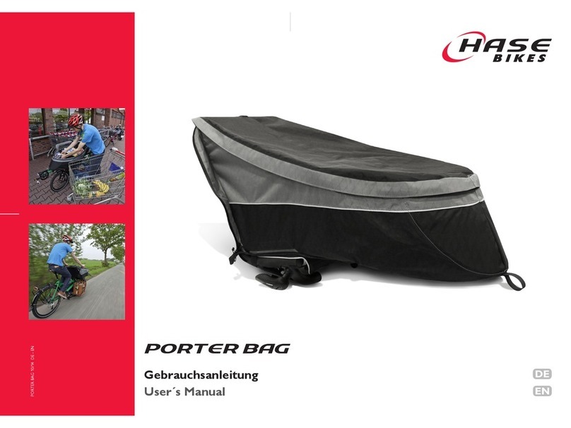
Bowdenzüge montieren
6. Jeweils ein Bremszug wird vom rechten Bremshe-
bel durch die Auflaufbremse zur rechten Brem-
szange, bzw. vom linken Bremshebel durch die
Auflaufbremse zur linken Bremszange geführt.
Verlegen Sie die 800mm Bowdenhülle vom
rechten Bremshebel zur Auflaufbremse.
Die Länge der Bowdenhülle von der Auflaufbrem-
se zu der rechten Bremszange beträgt 700 mm
Verlegen Sie die zweite 700mm Bowdenhülle vom
linken Bremshebel zur Auflaufbremse.
Die Länge der Bowdenhülle von der Auflaufbrem-
se zu der linken Bremszange beträgt 350 mm. Die
linke Bowdenhülle wird mit einer 135° Kabelfüh-
rung an der Bremse montiert.
Auflaufbremse einstellen
7 . Clipsen Sie die Lenkstange in die Kugelkopfmutter
am Lenker ein und stellen Sie das Vorderrad gera-
de. Schieben Sie den Gegenhalteklotz (1) an das
Gleitlager (2) und ziehen Sie M8 Madenschraube
(3) fest.
Nach der Längeneinstellung der Bremsstange
muss die Vorspannung der Feder eingestellt wer-
den. Lösen Sie dazu die M5 Madenschraube (4)
am Federgegenhalter. Schieben Sie den Feder-
gegenhalter gegen die Feder und ziehen Sie die
Madenschraube bei ausreichender Vorspannung
der Feder fest.
Hinweis:
Die Zugeinsteller mit Stellschraube (5) ermögli-
chen ein schnelles und einfaches Justieren.
Mounting the brake cable
6. Run one brake cable from the right brake lever
through the overrun brake to the right brake cal-
iper and the other one from the left brake lever
through the overrun brake to the left brake cali-
per.
Lay the 800mm cable housing from the right
brake lever to the overrun brake.
The length of the cable housing from the overrun
brake to the right brake calliper is 700 mm.
Lay the second 700mm cable housing from the
left brake lever to the overrun brake.
The length of the cable housing from the overrun
brake to the left brake calliper is 350 mm. The left
cable housing is mounted with a 135° cable guide
at the brake.
Adjusting the overrun brake
Clip the handlebar into the ball-head on the handle-
bar and straighten the front wheel. Place the counter
block (1) at the slide bearing (2) and tighten the M8
grub screw (3).
After adjusting the length of the brake rod, the pre-
load of the spring must be adjusted. To do this, loosen
the M5 grub screw (4) on the spring counterholder.
Push the spring counterholder against the spring and
tighten the grub screw if the spring when sufficiently
pretensioned.
Note:
The index adjusting barrels (5) allow quick and
easy adjustment. .
13
2
4
5
5
Trailer Option 11/18 DE-EN
www.hasebikes.com
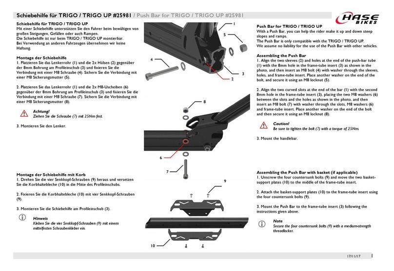
Gebrauch
Der KW-Nachläufer ist so konstruiert, dass mit weni-
gen Handgriffen der Nachläufer zum normalen KETT-
WIESEL umgebaut werden kann, und umgekehrt.
Es müssen lediglich das Vorderrad durch die Deichsel
ersetzt und die Bremsstange der Auflaufbremse ein-
geklickt werden - schon ist aus dem KETTWIESEL ein
Anhänger geworden.
Hinweis:
Wird die Bremsstange in der Kugelkopfschraube
am Lenker geklemmt, ist die Lenkung blockiert
und die Auflaufbremse aktiviert.
Entfernt man die Deichsel und trennt man die
Bremsstange vom Lenker, funktionieren die
Bremsen und die Lenkung wie an einem her-
kömmlichen KETTWIESEL.
Deichsel montieren
7. Lösen Sie den Schnellspanner und nehmen Sie
das Laufrad aus der Gabel. Die Deichsel wird wie
im Bild rechts an die Gabel geklemmt, so dass die
Gummikappe als Momentabstützung sich an der
Gabel abstützt.
Hinweis:
Sichern Sie den angekoppelten Trailer zusätzlich,
in dem Sie den Riemen um ein Rahmenrohr in
der Nähe der Kupplung schlaufen und mit der
Schnalle sichern.
Achtung!
Achten Sie darauf, dass der Sicherungsriemen
(1) sich nicht während der Fahrt im drehenden
Hinterrad des Zugfahrrades verfangen kann.
Befestigen Sie den Riemen ausreichend locker,
damit er sich bei Kurvenfahrt nicht spannt und
so die Fahrt beeinträchtig
Usage
The construction of the KETTWIESEL Trailer allows for
quick and easy conversion to a KETTWIESEL trike and
back again.
To turn the trike into a trailer, simply replace the front
wheel with the drawbar and click the brake rod of the
overrun brake into place.
Note:
When the brake rod is clicked onto the ball head
on the handlebar and the drawbar is clamped
into the fork, the steering unit is locked, and the
overrun brake is activated.
When the drawbar is removed and the brake rod
is uncoupled from the handlebar, the brakes and
steering function normally.
Mounting the drawbar
7. Mount the drawbar as shown in the picture. When
clamping the drawbar into the fork, be sure that
the rubber cap lie in front of the fork as torque
support.
Note:
Attach the Safety Strap to the towing bike by lo-
oping the strap around a frame tube near the
hitch and securing it with the buckle.
Caution!
Check the position of the Safety Strap (1) to make
sure that it cannot get caught in the rear wheel
of the towing bike while riding.
Be sure to make the Safety Strap long enough so
that it does not stretch tight and limit movement
while turning left or right.
1
Auaufbremse aktiviert
Overrun brake activated
Auaufbremse deaktiviert
Overrun brake deactivated
6Trailer Option 11/18 DE-EN www.hasebikes.com
Achtung!
Die dem Trailer Set zusätzlich beiligende Kugelkopf-
mutter (1) ausschließlich ist für die Montage an
KETTWIESELn mit Stahllenker (Baujahr vor 2016).
Achtung!
Laut StVZO sind bei Anhängern ,die breiter als 60cm
sind, zwei weiße Reflektoren in Fahrtrichtung vor-
geschrieben. Bringen Sie die beiliegenden Reflekto-
raufkleber wie Bild zu sehen, auf den Schutzblechen
des Nachläufers an.
Achtung!
Es darf keine gekröpfte Lenkübertragungsstange
verwendet werden, da diese den Belastungen durch
die Auflaufbremse nicht stand hält.
Reektoraufkleber
reector sticker
1
Caution!
The additional ball nut (1) included with the trailer
set is only for mounting on KETTWIESELn with steel
handlebar (year of construction before 2016).
Caution!
According to the German Road Traffic Licensing
Regulations (StVZO), two white reflectors are re-
quired for trailers wider than 60 cm in the direction
of travel. Attach the enclosed reflector stickers as
shown in the picture, to the fenders of the trailer.
Caution!
A cranked steering rod must not be used as this
can not withstand the loads caused by the overrun
brake!

Other HASE Bikes Bicycle Accessories manuals

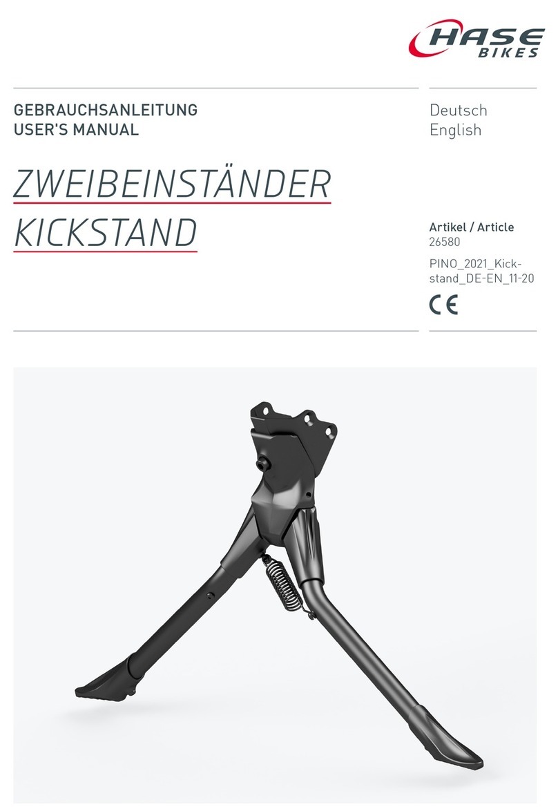
HASE Bikes Double Kickstand User manual

HASE Bikes

HASE Bikes Double Kickstand User manual

HASE Bikes 24298 User manual

HASE Bikes

HASE Bikes 24298 User manual

HASE Bikes 25286 User manual

HASE Bikes

HASE Bikes 25286 User manual

HASE Bikes VARIO KOMFORT User manual

HASE Bikes

HASE Bikes VARIO KOMFORT User manual

HASE Bikes RACK User manual

HASE Bikes

HASE Bikes RACK User manual

HASE Bikes 25403 User manual

HASE Bikes

HASE Bikes 25403 User manual

HASE Bikes PONCHO 21 User manual

HASE Bikes

HASE Bikes PONCHO 21 User manual

HASE Bikes 25535 User manual

HASE Bikes

HASE Bikes 25535 User manual

HASE Bikes SEATMESH User manual

HASE Bikes

HASE Bikes SEATMESH User manual

HASE Bikes PORTER BAG User manual

HASE Bikes

HASE Bikes PORTER BAG User manual

HASE Bikes 23298 User manual

HASE Bikes

HASE Bikes 23298 User manual

HASE Bikes 26580 User manual

HASE Bikes

HASE Bikes 26580 User manual

HASE Bikes VARIO KOMFORT User manual

HASE Bikes

HASE Bikes VARIO KOMFORT User manual

HASE Bikes 25981 User manual

HASE Bikes

HASE Bikes 25981 User manual

Popular Bicycle Accessories manuals by other brands

Sigma BC 906 user manual

Sigma

Sigma BC 906 user manual

Crivit 68643 instruction manual

Crivit

Crivit 68643 instruction manual

Surly Deck Bar instructions

Surly

Surly Deck Bar instructions

Polar Electro Y7 user manual

Polar Electro

Polar Electro Y7 user manual

FSA Tandem Crank ZS035 Service instructions

FSA

FSA Tandem Crank ZS035 Service instructions

NiteRider LUMINA MAX 2500 user guide

NiteRider

NiteRider LUMINA MAX 2500 user guide

OGK urban Iki Rear seat manual

OGK

OGK urban Iki Rear seat manual

Kesser K-FHA-2090 manual

Kesser

Kesser K-FHA-2090 manual

Tianjin Key-Disp KD59E user manual

Tianjin Key-Disp

Tianjin Key-Disp KD59E user manual

Giant Hookless WheelSystems user manual

Giant

Giant Hookless WheelSystems user manual

Brompton C Bag quick start guide

Brompton

Brompton C Bag quick start guide

FUXON Quattro Plus instruction manual

FUXON

FUXON Quattro Plus instruction manual

Bosch Bulls Aminga E1 Translation of the original operating instructions

Bosch

Bosch Bulls Aminga E1 Translation of the original operating instructions

Wuxi LingDe Microelectronics LD906GBU instruction manual

Wuxi LingDe Microelectronics

Wuxi LingDe Microelectronics LD906GBU instruction manual

TRP SPYRE installation instructions

TRP

TRP SPYRE installation instructions

Dan's Comp Front Load Stem installation manual

Dan's Comp

Dan's Comp Front Load Stem installation manual

BOB QR Series Quick release instructions

BOB

BOB QR Series Quick release instructions

Boogie Lockholder Install

Boogie

Boogie Lockholder Install

manuals.online logo
manuals.online logoBrands
  • About & Mission
  • Contact us
  • Privacy Policy
  • Terms and Conditions

Copyright 2025 Manuals.Online. All Rights Reserved.