Hasler HJ 3630 User manual

Mailing Systems
And Solutions HASLER
America’s better choice
®
An ISO 9001 Quality System
Certified company
Operating Guide
HJ 3630 Printing System

Introduction
All rights reserved. No part of this manual may be reproduced or transmitted in
any form or by any means, copied onto electronic media or translated into any
language without the manufacturer’s express written permission.
The manufacturer is not liable for any damage resulting either from incorrect use
or from repairs and modifications carried out by a third unauthorized party. This
manual was produced with great care. However, liability for any errors which it
may contain is excluded. The manufacturer reserves the right to make any
technical or design changes to the equipment during the development process.
All specified values are purely nominal. Consequently, any legal claims made on
the basis of this manual cannot be enforced.
The manufacturer is not liable for any damage or disturbance resulting from the
use of options or accessories which are not original products or do not have the
express approval of the manufacturer.
Trademarks:
HP is a registered trademark of the Hewlett-Packard Corporation.
Microsoft and Windows are registered trademarks of the Microsoft Corporation.

Contents
Contents
Table of Figures
1Introduction
1.1 Pictograms
1.2 How to Use this Manual
1.3 Important Terms and Abbreviations
1.4 System Requirements
2Security Advice
2.1 General Security Advice
2.2 Correct Handling of Ink Cartridges
2.3 Location of the Printer
2.4 Disposal
3Unwrapping and Assembly
3.1 Delivery
3.2 Unwrapping the Printer
3.3 Assembly
a) DDP setup
b) Connecting the offline Dreamfeeder to the DDP
4Description of the DDP
4.1 DDP Overview
4.2 Range of Application
4.3 Function Description
4.4 The Operator Panel
4.4.1 What do the keys mean?
4.4.2 Key combinations
4.5 The Display
4.6 Overview of the External Terminals
4.7 Description of the Emergency Stop “Loop”
5Startup and Operation
5.1 Inserting Ink Cartridges
5.2 Switching-on DDP
5.3 Position and Dimensions of the Print Media

Introduction
5.4 Adjusting Printer to the Print Media
5.5 Entering Position of the Print Media
5.6 Checking the Paper Transport
5.7 Adjustment of a Print Rotated by 180°
5.8 Width and Height Measurement of the Print Media
5.9 Test Print
6Calibrating the Print Units
6.1 Calibrating the Vertical Distances of the Print Units
6.2 Mutual Calibration of the Cartridges
6.3 Mutual Calibration of the Print Units
7General Information
7.1 Exchanging Ink Tray
7.2 Resetting the Ink Counter
7.3 Indication for Ink Cartridge Exchange
7.4 Cleaning the Print Nozzles
7.5 Day Counter
7.6 Service Counter
7.7 Job Counter
8The Main Menu
8.1 The “Quick“ Menu
8.2 Menu Overview
8.3 Printer Configuration
8.4 Job Parameters
8.5 Service
8.6 Language
8.7 Setting
8.8 Explanation of the Individual Menu Items
8.8.1 Printer configuration
8.8.2 Job Parameters
8.8.3 Service
8.8.4 Language
8.8.5 Setting
8.8.6 Initialization of the device
8.9 Printer Driver Installation

8.10Error Notifications
8.11Warning Notifications
9Appendix
9.1 Maintenance Instructions
9.1.1 Cleaning the ink cartridge
9.2 Interfaces
9.2.1 Centronics parallel interface
9.2.2 RS-232-C serial interface
9.3 Fonts
9.3.1 Terminology
9.3.2 Character set
9.3.3 Selecting the print fonts
9.4 Character Sets
9.4.1 7-bit character sets
9.4.2 8-bit character sets
9.5 Technical Data Model 630
10 Glossary

1 Introduction
With the Model 630 you chose an innovative digital printer featuring HP ink
jet technology for printing variable data, e.g. mass mailings with addresses,
serial numbers or other variable information and graphic elements. The device is
designed for the professional use at a high throughput.
In order to ensure long-time and, above all, safe use of the Model
630 and its components, you have to read and
adhere to the safety instructions in this user manual before
starting installation and operation. Please do always observe any
warnings and instructions that are directly attached to the
device.
All persons using the printer must also be familiarised with this manual.
Please do carefully keep this manual available in order to be able to check back
at any time.
1.1 Pictograms
General warnings
Warning against danger caused by electric current and
electric shock
Information/advice: indicates some important device handling
information

Introduction
1.2 How to Use this Manual
In the continuous text you will find general information and descriptions. These
are required to be able to execute subsequent working and operating steps.
The text is indicated by a dot when the technician or operator is expected to
carry out a work step. E.g.:
• Carry out the next step now.
• Now the next step.
Please do always read these work-step texts in order to obtain any necessary
information. Do not anticipate or ignore the manual; it keeps you from mistakes!
Chronology and manual consultation
The manual is chronologically structured, i.e. starting from the packaged delivery
condition up to the ready-for-operation state, followed by operation,
programming and, at last, technical information.
If you are not familiar with the printer, best read the manual sequentially. You
will be guided step by step and thus be able to start-up the printer easily and
quickly.
If you are already familiar with the Model 3630, it should be equally easy to
use the manual for reference purposes.
1.3 Important Terms and Abbreviations
It is important to know some terms and abbreviations related to the Model 630:
• cartridge = Crt = C, C1, C2, C3
• print unit = Unit = U, U1, U2
We refer to it as a unit since three cartridges are combined here.
• print media width = expansion of the print media in transport direction
• print media height = expansion of the print media at right angles to
transport direction
1.4 System Requirements
The Model 3630 is designed for the application at a PC (at least Pentium 500 MHz)
with parallel interface. It may be run by the operating systems Windows 2000 or
Windows XP.
You require a shielded, twisted, parallel interface cable (not included in delivery).
When operating with Windows 2000 und Windows XP, the printer may be
alternatively connected via USB cable.

2 Security Advice
Prior to initial operation, please do carefully read the following instructions for
the sake of both your own safety and printer operating safety. Do always
observe any warnings and instructions directly attached to the device. Do
carefully keep this manual available in order to be able to check back at any
time.
The Model 3630 digital printer exhibits state-of-the-art design and is safe to
operate. However, if not operated by instructed personnel, the device may bear
risks and dangers. The same applies to any usage that does not comply with its
original purpose or that is inappropriate.
Disregard may bear the danger of
• electric shock,
• injuries due to draw-in by rotating rollers,
• damage of the printer.

Security Advice
2.1 General Security Advice
Caution!
Please do carefully read these instructions.
Keep this guide for future reference and consultation.
Any instructions and warnings attached to the device must be
followed.
Setting-up
the printer When setting-up the printer, ensure safe and even
positioning. Tilting, inadvertent rolling or falling may cause
injuries.
The printer must be protected from humidity.
WARNING!
This is a device of class A. In living quarters it may cause
radio interference. In this case the operator can be claimed
to take appropriate measures.
Electric
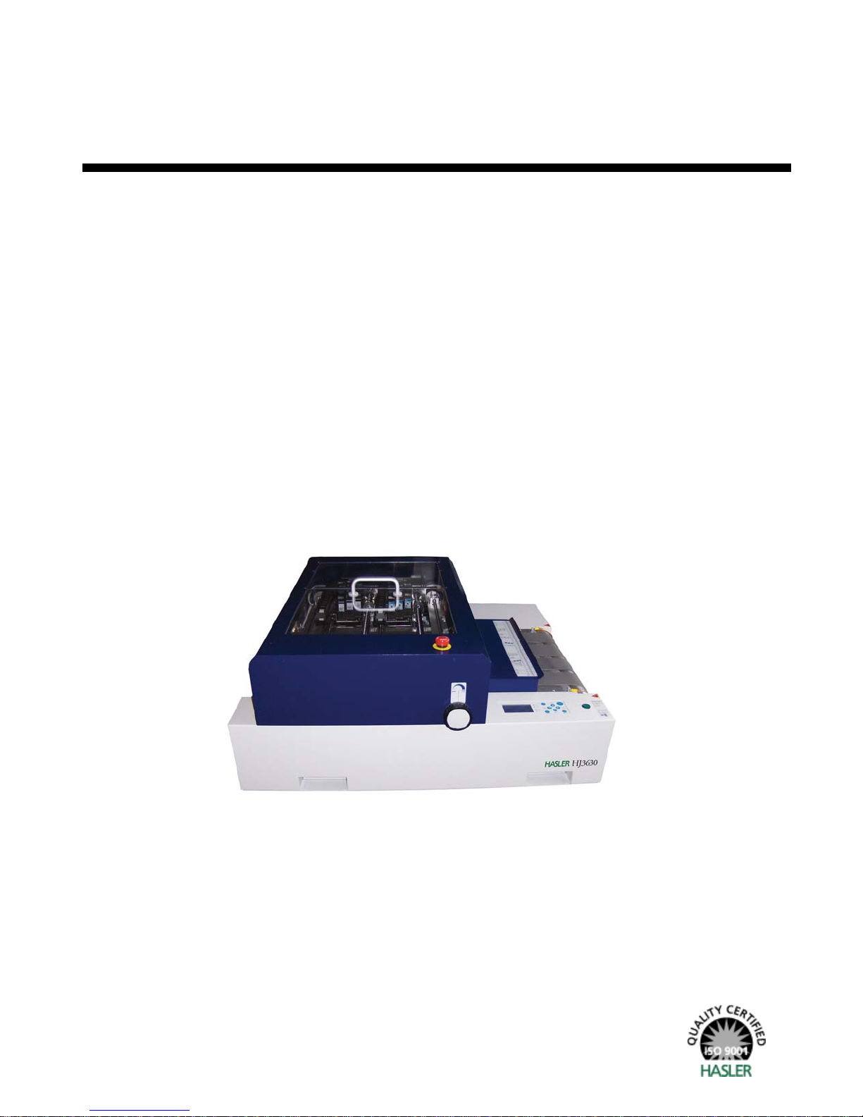
danger Depending on country-specific performance, the Model 3630
digital printer may only be applied at voltages of either
230 V/50 Hz or 115 V/60 Hz.
The power plug may only be plugged into a shockproof
socket! The shockproof protection may not be overridden by
an extension without protective earth conductor. Any
interruption of the protective earth conductor inside or
outside the device is dangerous and not permissible.
The device is double-pole fused! After a fuse protection
failure or deficiency, electric components inside the printer
may continue to be energised.
When connecting to the electricity network, follow the
electrical specifications on the type plate.
Check the voltage setting at the electricity input module of
the device.
Place all cables and supply lines in such a way so that no one
can stumble across them. Do not place any objects on the
supply lines.
If the device is not used over a longer period of time, it
should be disconnected from the electricity network. In doing
so, you make sure to prevent it from damage caused by
overvoltage.
Protect the printer from humidity. Penetration of moisture
into the device bears the danger of electric shock.
Never open the device. For reasons of electrical safety, it
may only be opened by authorised service personnel.
Operating
safety Never reach into the running machine!
There is danger of injuries caused by draw-in or squeezing at
rotating rollers. Moreover, keep long hair and clothes away

from the running machine.
To avoid damage of the device, only factory–approved
accessories should be used.
Cleaning the
device Prior to each cleaning process, the device must be
disconnected from the electric network.
For cleaning, do not use liquid or aerosol cleaners; do only
use a water-moistened cloth.
Let the
printer be
checked by a
service
technician!
In the following cases, unplug the connector and turn the
device over to an authorised service technician:
• if the power cable or plug is worn or damaged
• if water or other liquids have penetrated into the
device
• if the device does not function properly despite
adherence to the quoted instructions
• if the device has fallen down or if the casing is
damaged
• if the device exhibits peculiar deviations from normal
operation
Spare parts For repairs, only original spare parts or spare parts that
correspond to the originals may be used.
Repairs Do not disassemble the printer further than described in this
manual. It is not admissible for unauthorised persons to open
the device. Repairs may only be carried out by authorised
staff.
Prohibition of reconstruction and modification:
Due to safety reasons, any arbitrary reconstructions and
modifications are not permissible.
For any questions related to service and repairs, please refer to
your service partner. Thus, you ensure safe operation for your
printer.
2.2 Correct Handling of Ink Cartridges
Keep ink cartridges unavailable for children. Normally, the ink
cannot leak. Immediately clean your skin from ink under running
water. In case ink has entered your eye, immediately rinse it
with plenty of water.
The ink cartridge should not be shaken, dropped or hit against the palms or hard
surfaces.
Install the ink cartridge immediately after removing the protective tape. The
cartridge may not be used after date of expiry!

Security Advice
Do not try to open or refill a cartridge; this can lead to damage of the printer.
2.3 Location of the Printer
When setting-up the printer, make sure that it is located on a plain and even
surface which is larger than the printer.
The base platform for the printer must be sufficiently stable. Tilting or dropping
of the device may lead to injuries or device damage.
Choose the location of operation or storage in a way that protects the device
from heavy fluctuations of temperature and humidity, from direct solar radiation
and excess heat.
The printer must not be exposed to vibration or shock.
Place the printer in such a way that the power plug can be easily disconnected
from the power socket at any time.
Make sure that enough footprint is available for the feeder (in case that a feeder
is used).
2.4 Disposal
The printer must not be disposed of by domestic waste. Please dispose of the
printer according to the legal requirements.

3 Unwrapping and Assembly
3.1 Delivery
The Model 3630 is delivered in appropriate packaging and in such a way that
it - at regular transport conditions - reaches its destination safely and
undamaged.
The carrier is liable for damages during transport. Transport and storage should
take place under normal circumstances, i.e. at temperatures between +5°C and
+70°C (between 41°F and 158°F) and a relative humidity of 80% maximum. At
non-admissible conditions, damages may develop which are not visible from
outside.
The printer is fixed in the transport box by transportation locks. Loosen the
transportation locks before you take out the printer. Do only lift the DDP at the
recessed grips provided for this purpose. The device may not be lifted at the
parts of the casing.
Figure 3-1: Delivery
Only lift device at the recessed grips!
3.2 Unwrapping the Printer
Packaging
In case the printer must be sent back, the Model 3630 packaging must be used.
You may also send the packaging back to your supplier.
In case the packaging is no longer needed, please dispose of it in an
environmentally suitable manner.

Unwrapping and Assembly
Scope of delivery
Use the following list to check whether all parts of the DDP are entirely present
and undamaged:
DDP parts list
Main device DDP
with 2 print units
User manual on CD-ROM incl. driver software
Additional components:
• Dreamfeeder F635 (otional)
• Connecting cable “Plug & Print“
• Rack for Dreamfeeder (optional)
•

3.3 Assembly
As a standard, the DDP is operated in connection with the Dreamfeeder. Due to
transport reasons, the devices are separately wrapped and shipped. Before initial
operation, the two devices must be linked with each other mechanically and
electrically. Additionally, all transport locks must be removed.
Sequence of assembly:
Caution: When operating the Model 3630 without the RENA Dreamfeeder, the points b
and c do not apply.
a) DDP setup
• When setting up, take care that there is still sufficient space on the rear side of
the device for having direct access to the interfaces.
• Ensure that the device is switched off and that the socket is provided with an
intact protective earth conductor. Afterwards, plug the power cable into the power
input module on the right side of the device and into the power socket.
Figure 3-2: Assembly
Power input module Rear slots for support (standard)

Unwrapping and Assembly
b) Connecting the offline Dreamfeeder to the DDP
In order to make sure that the Dreamfeeder feeds the print media into the
printer from the correct height, the Dreamfeeder is positioned on a supporting
rack. To do this, align the Dreamfeeder in such a way that the two positioning
fingers of the support are located on the same side as the ejector roller of the
Dreamfeeder, as shown in the following illustration.
Figure 3-3: Connecting the Dreamfeeder
Put the two plugs of the Dreamfeeder through the bored hole on the upper side
of the support and place the Dreamfeeder on the support in such a way that the
thread bolts fit into the provided bored holes.
Positioning
finger
Ejector roller

Subsequently, place the support approx. 15 cm before the DDP. By doing this,
position the positioning fingers in front of the respective slots of the DDP on the
right side of the device. Connect the Dreamfeeder (RS 232 input) to the
(RENA Dreamfeeder output). Lock the connection by means of screwing the
connectors. With the help of this interface, the DDP and the Dreamfeeder are
able to communicate with each other in an intelligent way.
Now you can fit the positioning hooks into the rear slots at the DDP. Due to the
separation of the print media, it is possible that between the DDP and the
Dreamfeeder a difference of potential will establish. For the sake of discharge of
electrostatic charging, the earthing strap at the slide plate of the DDP is screwed
to the Dreamfeeder. With this, the DDP and the Dreamfeeder are readily aligned
and connected to each other.
Figure 3-4: Connecting the Dreamfeeder 2
External power
Connection to the PC IEEE
1284 Parallel, Centronics
Serial interface for
the Dreamfeeder

Unwrapping and Assembly
e) Positioning in case of narrow print media
As a standard, the Dreamfeeder is aligned with the help of a support at the rear
positioning slots at the DDP. The Dreamfeeder then supplies the print media at a
central position to the conveyor belt to position A. At the front right-hand device
angle, the two positions are schematically illustrated.
Figure 3-5: Dreamfeeder positioning A

In case the print medium covers less than three suction grooves, the
Dreamfeeder should be replaced. Thus, the risk of the edges or angles bending
upwards and the risk of a paper jam can be reduced. The support of the
Dreamfeeder is then relocated to the front position, i.e. is hooked into the front
slots. In the following illustration, the Dreamfeeder is pictured at the front
position B with a small envelope. The print medium is fed at centre position to
the second belt.
Figure 3-6: Dreamfeeder positioning B

Unwrapping and Assembly
On the above plate, those formats are given which should be fed at centre
position to the second belt.
If the Dreamfeeder has been replaced, it is absolutely necessary to also
adjust this within the device offset and the offset setting in FlexMail.
Otherwise, printing and the adjusted print area will not be consistent with
each other.
To do this, 42.5 mm must be added to the previously set value.
In case the height of the print medium should be less than 70 mm (caution: the
DDP is not specified for this!), then the print media should be fed at centre
position to the transport belt under position A.
You may read-off the correct offset at the ruler of the safety cover of the paper
infeed side. Feed a print medium and position it below the safety cover. Read-off
the rear value of the print medium edge. In the following illustration, a C5
envelope was fed into the device at position A.

Figure 3-7: Read-off the offset
At the ruler, a value of 9.8 cm can be read-off. Take over this value as the offset
value in FlexMail.
Figure 3-8: Set the offset in FlexMail
Other manuals for HJ 3630
1
Table of contents
Other Hasler Printer manuals