User Manual Version 3.1 7
Table of Figures
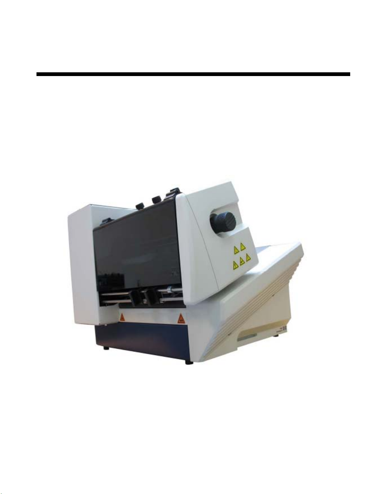
Figure 1: HJ700 overview frontside .........................................................................16
Figure 2: HJ700 overview rear side .........................................................................17
Figure 3: HJ700 overview frontside with open cover ..................................................18
Figure 4: Mounting I............................................................................................... 20
Figure 5: Mounting II.............................................................................................. 21
Figure 6: The operator panel....................................................................................23
Figure 7: Main display............................................................................................. 26
Figure 8: Inserting the ink cartridge.......................................................................... 31
Figure 9: Lock the restraining lever........................................................................... 31
Figure 10: Adjusting the separation ..........................................................................33
Figure 11: Separation fingers................................................................................... 34
Figure 12: Paper side guide positions for C5 envelope ................................................. 35
Figure 13: Positioning the material ...........................................................................35
Figure 14: Position of paper sensor........................................................................... 36
Figure 15: Adjusting the runner................................................................................36
Figure 16: Thickness adjustment knob ......................................................................37
Figure 17: Adjusting the printer to the material thickness ............................................ 38
Figure 18: Testprint................................................................................................40
Figure 19: Keep Alive function..................................................................................50
Figure 20: CARRIAGE CORRECT. ..............................................................................52
Figure 21: ADJUST TOF........................................................................................... 53
Figure 22: Difference Nor/Rev, transport direction ......................................................64
Figure 23:LEFT MARGIN, transport direction............................................................... 65
Figure 24:TOP MARGIN, transport direction................................................................ 65
Figure 25: Adjust Print Head sample printouts............................................................ 76
Figure 26: Pattern A ............................................................................................... 76
Figure 27: Pattern A with defects.............................................................................. 77
Figure 28: Cartridge contacts................................................................................... 77
Figure 29: Pattern B ............................................................................................... 77
Figure 30: Sample character set print ....................................................................... 78
Figure 31: Sample setting dump print .......................................................................79
Figure 32: Sample Input Buffer Dump print................................................................80
Figure 33: New Hardware Wizard .............................................................................84
Figure 34: Recommended install procedure................................................................84
Figure 35: Properties of unspecified device ................................................................ 86