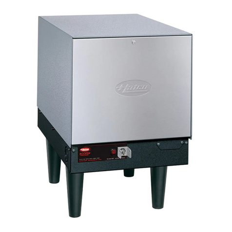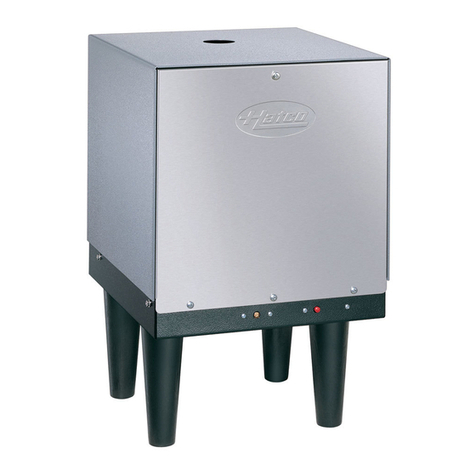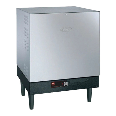
OPTIONS (NOT FOR RETROFIT)
❑Stainless Steel Bo y, Base, an Si es
❑Pressure Re ucing Valves (Brass or Iron)
❑6"-7" (152-178 mm) A justable Stainless Steel Legs (4)
❑Floor Mounting Har ware
❑Security Package
ITEM#
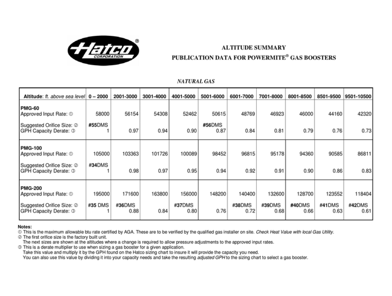
PMG-60 Input 58,000 BTUs/Hour.
Output – 46,000 = 13.4kW
PMG-100 Input 105,000 BTUs/Hour.
Output – 84,800 = 24.8kW
PMG-200 Input 195,000 BTUs/Hour.
Output – 156,000 = 45.7kW
SPECIFICATIONS
Capacity
Mo el PMG-60 & optional PMGH-60 Hoo
245⁄8"
(625 mm)
185⁄8"
(473 mm)
203⁄8"(518 mm)
Alternate
TPRV on back
TPRV
241⁄2"(622 mm)
6" (152 mm)
4" (102 mm) diameter flue adapter
FRONT VIEW RIGHT SIDE VIEW
243⁄8"(619 mm)
67⁄8"
(175 mm)
Electrical
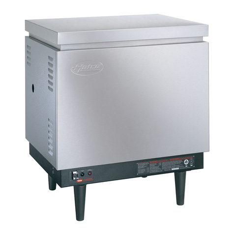
POWERMITE®
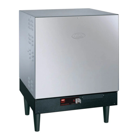
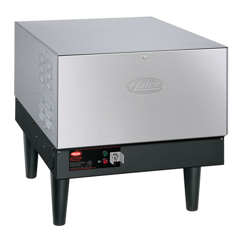
GAS BOOSTER WATER HEATERS
Models PMG-60, PMG-100, PMG-200
Mo els PMG-100 & PMG-200
25"
(635 mm)
271⁄2"(699 mm) PMG-100
36" (914 mm) PMG-200
203⁄4"(527 mm)
6" (152 mm)
REAR VIEW
RIGHT SIDE VIEW
Water
Outlet
Water
Inlet
Gas
Inlet
Alternate
Flue
Location
TPRV
4" (102 mm)
Vent Adapter
Water Outlet
Water Inlet
Gas Inlet
DIMENSIONS
PMG-60: 203/8"W x 241/2"D x 245/8"H* (518 x 622 x 625 mm).
PMG-100: 271/2"W x 203/4"D x 31"H* (699 x 527 x 787 mm).
PMG-200: 36"W x 203/4"D x 31"H* (914 x 527 x 787 mm).
PMGH-60 Hoo : 243/8"W x 133/8"D+x 67/8"H•(619 x 340 x 175 mm).
* Height inclu es 6" (152 mm) legs.
+A4" (102 mm) for flue a apter.
•A s 4" (102 mm) to wi th an 57/8"(149 mm) to height of PMG-60.
PRODUCT SPECS
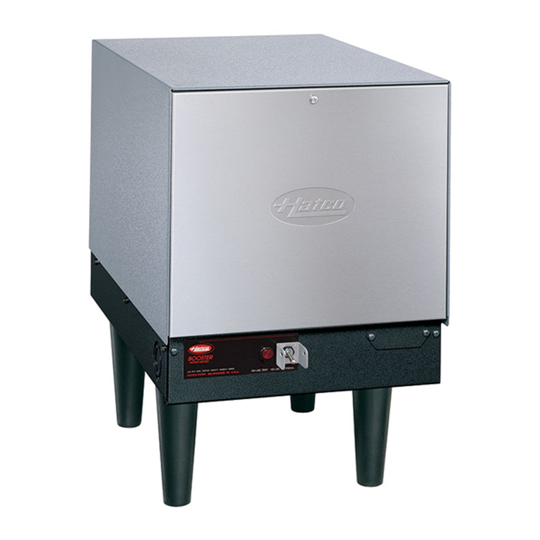
Gas Booster Water Heater
The Gas Booster Water Heater to supply the final 180°F (82°C)
rinse for the ishwasher shall be a Hatco Powermite®Mo el ...., as
manufacture for commercial use by the Hatco Corporation,
Milwaukee, WI 53234 U.S.A.
With 24/7 service (U.S an Cana a only), the booster shall have
the capacity to heat ....gph (lph) from 110°F to 180°F (43°C to
82°C) an it shall be rate at ....btu, 120 volts, single phase. The
stainless steel tank shall be esigne for a working pressure of 150
psi (1034 kPa) an hy rostatically teste at 300 psi (2069 kPa).
The heater shall be complete with all internal plumbing, inclu ing
3
⁄
4
" NPT pipe an fittings from inlet an outlet. All controls shall
be built-in, an carry safety approval in accor ance with
ANSI 21.10.3. Sanitary approval shall be in accor ance with
NSF Stan ar 5. Proper surface mounting circuit breaker or fuse
isconnect switch shall be provi e by electrical contractor.
The gas fire heating system shall be controlle by close
tolerance immersion thermostats. The booster shall be protecte
with high temperature limit switch (ECO) an low water cut-off.
The heater shall consist of stainless steel front, top, an stainless
steel a justable legs or stainless steel front an silver-gray
hammertone si es an back with stan ar 6" (152 mm) legs.
The heater shall inclu e a temperature/pressure relief valve,
high-temperature limit, pressure re ucing valve with bypass,
in icating temperature/pressure gauge, shock absorber, an
blen e phosphate water treatment system.
PMG-60 120 VAC, 210 watt, 1.75 amps.
PMGH-60 120 VAC, 18 watt, 0.15 amps.
PMG-100/200 120 VAC, 360 watt, 3.00 amps.
PMG-60 Gas – 1⁄2" NPT, Water – 3⁄4" NPT,
Electric – 120 VAC, 15 amp.
PMG-100/200 Gas – 3⁄4" NPT, Water – 3⁄4" NPT,
Electric – 120 VAC, 15 amp.
All Mo els Natural or Propane Gas
Fuel
Electrical
PMG-60 Direct – combustion air enters
bottom, flue gasses exit si es at
top of unit.
PMG-100/200 Direct – combustion air enters bottom,
flue gasses exit right si e or back
at top of unit. 4" (102 mm) flue roun .
ACCESSORIES
❑Exhaust Hoo PMGH-60 (For PMG-60 only)
❑High Altitu e Orifice Kit
All Mo els 150 PSI max. Relief valve set at
150 PSI, 210°F (99°C)
^Before installing any metho of venting you shoul contact the local co e
authority or your gas supplier to make sure that the final installation will be
acceptable to the authorities who have juris iction.
The proper metho of venting a power vente gas appliance is too
complicate to cover in this specification sheet an is explaine in etail
in the National Fuel Gas Co e. Before installing the venting system, the
person or agency making the installation must be familiar an experience
with the gui elines of the National Fuel Gas Co e.
ALL INSTALLATIONS MUST BE MADE BY A QUALIFIED
INSTALLER IN ACCORDANCE WITH THE NATIONAL
FUEL GAS CODE OR LOCAL CODES.
Water Column
Gas Type Minimum Maximum
Natural 5.0" (127 mm) 10.5" (267 mm)
Propane/LP 11.0" (279 mm) 13.0" (330 mm)
Gas Inlet Pressure
Water Column At Pressure Tap
Gas Type High Burn
Natural 3.5" ( 89 mm)
Propane/LP 10.0" (254 mm)
Operating Pressure Specifications at Manifol
PMGH-60 4" (102 mm) iameter vent pipe a apter
PMG-100/200 Force raft system with 4" (102 mm)
iameter vent pipe a apter.
PMG-60 130 lbs. (59 kg) ry.
PMG-100 180 lbs. (82 kg) ry.
PMG-200 215 lbs. (98 kg) ry.
Shipping Weight
31"
(787 mm)
271⁄2"(699 mm) PMG-100
Water Outlet
Electrical
Electrical
Water Inlet
Gas Inlet
36" (914 mm) PMG-200
203⁄4"(527 mm)
251⁄4"
(641 mm)
6" (152 mm)
FRONT VIEW
LEFT SIDE VIEW
Water
Outlet
Water
Inlet
Gas
Inlet
Alternate TPRV
Location
Operating Water Pressure
Fluing
Connections
HATCO CORPORATION P.O. Box 340500 Milwaukee, WI 53234-0500 U.S.A. • (800) 558-0607 • (414) 671-6350
Fax (800) 543-7521 • Int’l. Fax (414) 671-3976 • www.hatcocorp.com • E-mail: equipsales@hatcocorp.com
Vent^
Form No. PMG Spec Sheet
Printe in U.S.A.
January 2007
