Haws 1119HO Guide

10/20 MODEL 1119HO/1119HO2 PAGE 1 OF 7
1455 Kleppe Lane Sparks, NV 89431-6467 (775) 359-4712 Fax (775) 359-7424
No. 0510001123 (1)
Model 1119HO/1119HO2
Drinking Fountain
INSTALLATION, OPERATION
&
MAINTENANCE INSTRUCTIONS
LIMITED WARRANTY
HAWS warrants that this specific product is guaranteed against defective material or
poor workmanship for a period of one year from date of shipment. HAWS liability
under this warranty shall be discharged by furnishing without charge F.O.B. HAWS
Factory any goods, or part thereof, which shall appear to the Company upon
inspection to be of defective material or not of first class workmanship, provided that
claim is made in writing to Haws within a reasonable period after receipt of the
product. Where claims for defects are made, the defective part or parts shall be
delivered to the Company, prepaid, for inspection. HAWS will not be liable for the
cost of repairs, alterations or replacements, or for any expense connected therewith
made by the owner or his agents, except upon written authority from HAWS,
Sparks, Nevada. HAWS will not be liable for any damages caused by defective
materials or poor workmanship, except for replacements, as provided above. Buyer
agrees that HAWS shall not be liable for general, special, or consequential damages
claimed to arise under the contract of sale. The drinking fountain manufactured by
HAWS is warranted to function if installation and maintenance instructions provided
are adhered to. The units also must be used for the purpose for which they were
intended.
NO OTHER WARRANTIES EXPRESSED OR IMPLIED ARE AUTHORIZED,
PROVIDED OR GIVEN BY HAWS.
CAUTION! Prior to making any electrical connections, verify with a voltmeter that power
from the service panel is off.
SHOULD YOU EXPERIENCE DIFFICULTY WITH THE INSTALLATION OF THIS
MODEL PLEASE CALL:
TECHNICAL SUPPORT: 1-800-766-5612
FOR CUSTOMER SERVICE: 1-888-640-4297
NOTE TO INSTALLER: Please leave this information with the Maintenance Department.

10/20 MODEL 1119HO/1119HO2 PAGE 2 OF 7
RECOMMENDED TOOLS: Hack saw, pipe joint sealant, screwdriver, level, 12" adjustable
wrench, 10" pipe wrench, 5/64“ hex key wrench, 9/16”, 1/2", 7/16” socket wrench or open-end
wrench.
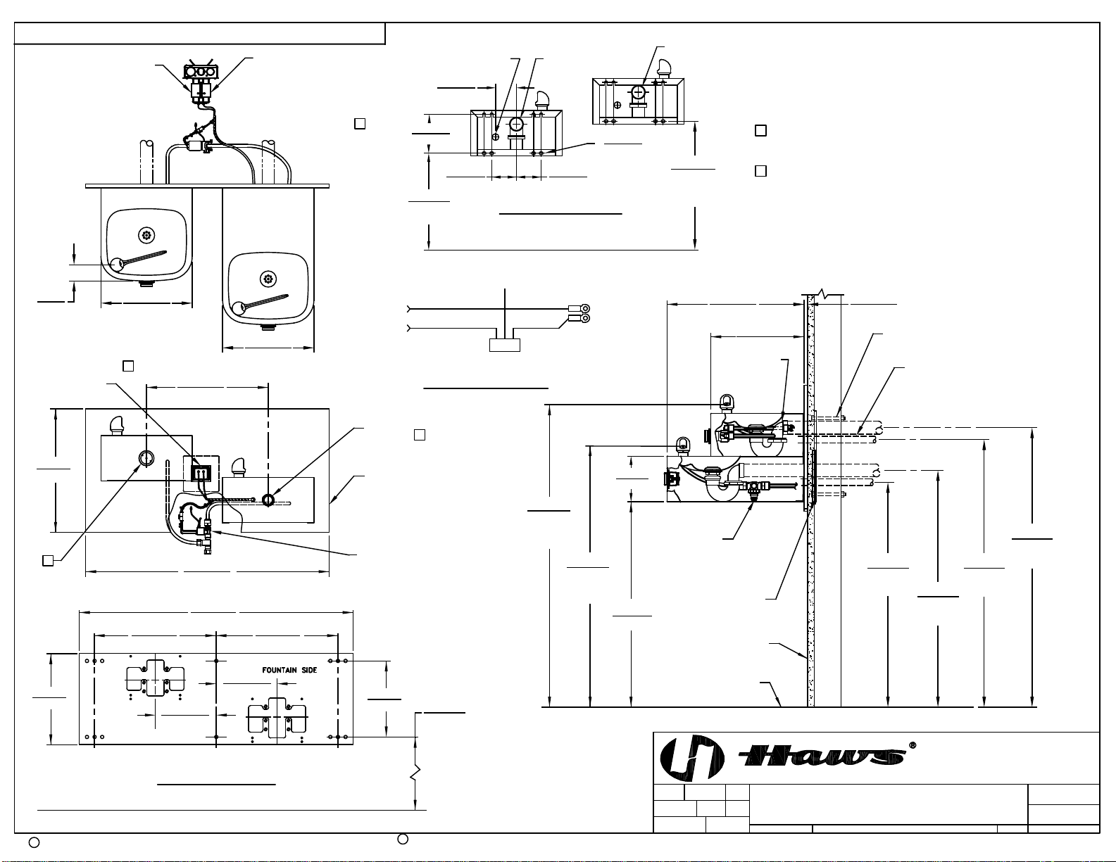
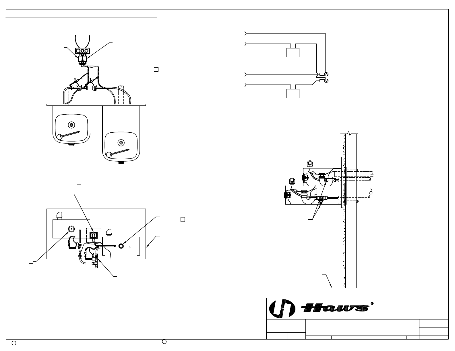
LOCATION OF UNIT: The Model 1119HO/1119HO2 Drinking Fountain is a wheelchair
accessible drinking facility. The height dimensions shown, meet current ADA requirements.
When installing this unit, local, state or federal codes should be adhered to. If height other
than shown is required, then dimensions must be adjusted accordingly.
SUPPLY LINE: The minimum recommended line size is 1/2“IPS with 30-90 psi (2-6 ATM)
flowing pressure. Where sediment or mineral content is a problem, an inlet filter is
recommended.
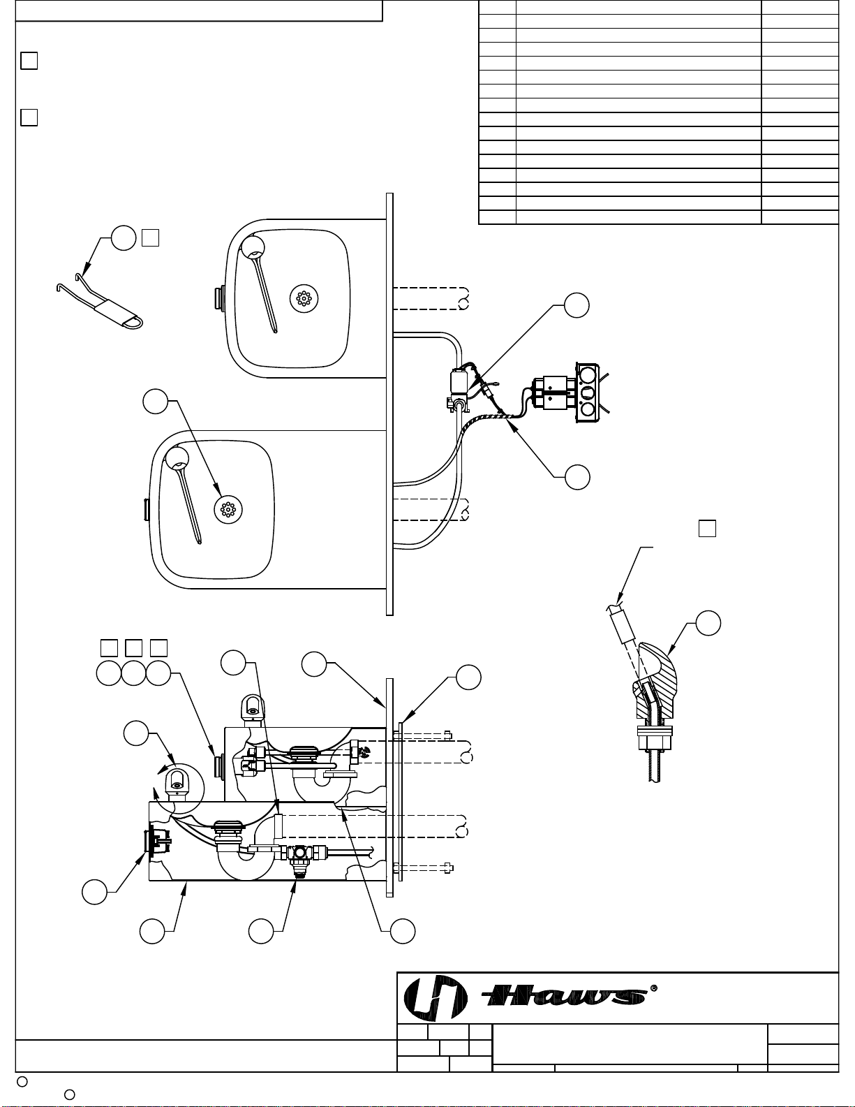
PLUMBING CONNECTIONS: Inlet is 3/8” O.D. compression fitting. Waste outlet is female 1-
1/4” NPT.
ELECTRICAL CONNECTIONS: Drinking Fountain may be mounted on external wall of
building provided transformer shall be mounted inside the wall and protected from
water as shown on RKHO Series O&M details (page 8) per NEC/CEC and local code.
Sensor(s):
1119HO with RKHO.120/120P:120 x 24 VAC, 60Hz, .68 AMPS.
1119HO with RKHO.240:240 x 24 VAC, 60Hz, .68 AMPS.
1119HO2 with RKHO.120/120P:120 x 24 VAC, 60Hz, 1.36 AMPS.
1119HO2 with RKHO.240:240 x 24 VAC, 60Hz, 1.36 AMPS.
MAINTENANCE: Periodically clean the strainer (Located inside push button valve on Model
1119HO). Refer to 5874 Series Valve Manual for more information.
INSTALLATION PROCEDURE
GENERAL NOTES:
1. For all plastic push-in type fitting connections, only connect NSF-61 copper or
plastic tubing. Stainless steel or glass tubing is not recommended. The
following assembly instructions must be followed to ensure a watertight
connection:
a. Cut tubing square and clean.
b. Mark from end of tube the length of insertion (See table below).
c. Push tube into the fitting until it bottoms out.
d. To remove, depress collet and pull tubing out.
Tube Sizes
O.D.
Tolerance
Insertion Depth
1/4”
±.005”
11/16”
3/8”
±.005”
3/4”
1/2”
±.005”
7/8”

10/20 MODEL 1119HO/1119HO2 PAGE 3 OF 7
INSTALLATION PROCEDURE…
STEP 1: Thoroughly flush supply line to remove all foreign matter. Connect 1/2” IPS supply
screwdriver-stop (not supplied). Install supply 3/8” O.D. tubing (supplied), between
screwdriver-stop and solenoid valve (Cut tubing to proper length and follow general
notes for proper connection procedures for push-in type fittings). Connect 3/8”O.D.
tube between fountains and solenoid valve outlet(s) (if not already connected).
STEP 2:Open screwdriver-stop wide open while checking for leaks at all connections. Also,
check waste for leaks.
STEP 3: Model 1119HO (only): 5874 Series Valve –Adjust bubbler stream height using a
small flat-head screwdriver inserted through a hole in the center of the push button
for increased flow turn clockwise and for decreased flow turn counterclockwise. If
flow problems arise, see troubleshooting guide for additional instructions to correct
problem. Bubbler stream may lower during short break-in period. Set initial stream
height a little high to minimize or eliminate the need for break-in period readjustment.
Model 1119HO/1119HO2: 5867 Valve Pressure Regulator –Adjust bubbler stream
height using the black pressure regulator mounted inside bracket that has HO sensor
unit, by loosening the locknut and rotating the knob clockwise to increase flow or
counterclockwise to reduce flow. Tighten the locknut and check flow height. Repeat
these steps until the bubbler flow height is correct.
STEP 4: RKHO Series Transformer and Sensor Setup: Refer to the RKHO Series manual
for instructions (supplied).
MAINTENANCE
STEP 1: Periodically clean the strainer located in the push button valve body on Model
1119HO (Refer to 5874 Series Valve Manual for more information).
5874 Series VALVE TROUBLESHOOTING (Model 1119HO Only)
PROBLEM
REPAIR CHECKLIST
1.
Insufficient bubbler flow.
1a.
Check that inlet screwdriver stop valve (not
supplied) is in wide-open position.
b.
Verify minimum 30 psi flowing supply pressure.
c.
Clean strainer. See 5874 Series Valve Manual.
d.
Adjust valve to increase flow. Use front adjust
screw or see 5874 Series Valve Manual.
For more information about Haws products, see our website: www.hawsco.com
© 2020 Haws®Corporation –All Rights Reserved
HAWS® and other trademarks usedin these materials are the exclusive property of Haws Corporation.

APPROVED
DRAWN
PART NUMBER
SCALE: SHEET OF
REVISION
DRAWING TYPE: SIZE: A
BYECN NO.
PAGE
DATE
DATE
ECN:
REVISED PER
CHKD
Haws Corporation - All Rights Reserved
HAWS and other trademarks used in these materials are the exclusive property of Haws Corporation.
CR
MODEL(S)
1455 KLEPPE LANE
SPARKS, NEVADA 89431
(775) 359-4712 FAX (775) 359-7424
E-MAIL: HAWS@HAWSCO.COM
WEBSITE: WWW.HAWSCO.COM
THIS DOCUMENT IS TRUE AND CORRECT AT TIME OF PUBLICATION. CONTINUED PRODUCT IMPROVEMENTS
MAKE SPECIFICATIONS AND MEASUREMENTS SUBJECT TO CHANGE WITHOUT NOTICE.
WHEN ORDERING PARTS PLEASE SPECIFY MODEL NUMBER.
FV
10/23/20
1
0510001123
1119HO/1119HO2
1:4
12
FV
10/29/20
5605
SLS
4 OF 7
PARTS BREAKDOWN
5605
2020
FV
8
5
10
9
(OPTIONAL)
2
A
5REF
34
1
STRAINER, WASTE ASSY1
BACK PANEL
2
BUBBLER HEAD ASSY, PCP
3PUSH BUTTON ASSY
4
BUTTON, PUSH, FLANGED, PCP W/ VALVE
5PLATE, BOTTOM6
8
9
5703M
PBA6
5874PBF
PBM1105
0004023580
6462
ITEM DESCRIPTION 1119
* DENOTES OPTIONAL PART.
VALVE REPAIR KIT VRK5874
TRAP 0005982900
10
*PLATE, MOUNTING 6700.4
PLATE, BOTTOM PBM1109
7
6
7
1
ROTATED 90° INTO VIEW
DETAIL A
REMOVE INSERT
WITH 5/16 HEX SOCKET
(NOT SUPPLIED)
2
NOTES:
1 5874PBF (ITEM 2) INCLUDES VRK5874 CARTRIDGE ASSEMBLY
(ITEM 3), PBA6 FLANGED PUSH BUTTON (ITEM 4) AND
SPANNER WRENCH (ITEM 15).
2 ENSURE TUBE IS DISCONNECTED FROM PUSH BUTTON VALVE
BODY PRIOR TO REMOVAL. APPLY ONE DROP OF LOCTITE
222MS TO NOZZLE THREADS PRIOR TO FASTENING BACK
ONTO BUBBLER HEAD. RE-ATTACH TUBE TO VALVE.
PARTS BREAKDOWN
11
SOLENOID
12
13 VRKH03
WIRING HARNESS VRKH02
14 PRESSURE REGULATOR 5867
SENSOR VRKH01
11
14
12
13
11
15 1
15 SPANNER WRENCH 0006983506
1119HO SHOWN
1119HO2 ON SHEET 2

APPROVED
DRAWN
PART NUMBER
SCALE: SHEET OF
REVISION
DRAWING TYPE: SIZE: A
BYECN NO.
PAGE
DATE
DATE
ECN:
REVISED PER
CHKD
Haws Corporation - All Rights Reserved
HAWS and other trademarks used in these materials are the exclusive property of Haws Corporation.
CR
MODEL(S)
1455 KLEPPE LANE
SPARKS, NEVADA 89431
(775) 359-4712 FAX (775) 359-7424
E-MAIL: HAWS@HAWSCO.COM
WEBSITE: WWW.HAWSCO.COM
THIS DOCUMENT IS TRUE AND CORRECT AT TIME OF PUBLICATION. CONTINUED PRODUCT IMPROVEMENTS
MAKE SPECIFICATIONS AND MEASUREMENTS SUBJECT TO CHANGE WITHOUT NOTICE.
WHEN ORDERING PARTS PLEASE SPECIFY MODEL NUMBER.
FV
10/23/20
1
0510001123
1119HO/1119HO2
1:4
22
FV
10/29/20
5605
SLS
5 OF 7
PARTS BREAKDOWN
5605
2020
FV
5
9
A
1
PARTS BREAKDOWN
12
13
810
(OPTIONAL)
11
6
714 1119HO2 SHOWN
1119HO ON SHEET 1

TO FLOOR
406mm
254mm
10"
305mm
12"
(OPTIONAL, HAWS 6700.4)
MOUNTING PLATE
406mm
813mm
32"
914mm
36"
16" 16"
702mm
27-5/8"
BACK PANEL
305mm
2-1/8"
54mm
413mm
16-1/4"
12"
305mm
12"
406mm
16"
27"
1029mm
40-1/2"
12.7mm457mm
311mm
12-1/4"
18" (BACK PANEL)
1/2"
203mm
8"
8"
203mm
6"
152mm
1-1/4" NPT
TRAP
(SUPPLIED)
WALL FACE
FLOOR LINE
(OPTIONAL)
MOUNTING PLATE
3/8" MOUNTING BOLTS
(NOT SUPPLIED)
C
9.5mm
MOUNTING
3-1/4"
83mm
TO FLOOR
27-7/16"
697mm
83mm
BACK VIEW
MOUNTING DETAIL
3-1/4" SLOTS
2-3/4"
SUPPLY
5-1/8"
130mm
70mm
WASTE
C
3/8"
Ø
33-1/16"
TO
FLOOR
840mm
WASTE
686mm
876mm
34-1/2"
(TO SPOUT
1. HOLD ROUGH-IN DIMENSIONS ± 1/4" (6.4mm).
2. WHEN INSTALLING THIS UNIT, LOCAL, STATE, OR FEDERAL
CODES SHOULD BE ADHERED TO. FOR INSTALLATION HEIGHTS
OTHER THAN SHOWN, DIMENSIONS MARKED (*) MUST BE
ADJUSTED ACCORDINGLY.
3 REFER TO 5874 SERIES/VRK5874 OPERATION AND MAINTENANCE
MANUAL FOR PUSH BUTTON AND VALVE INSTALLATION AND
MAINTENANCE INSTRUCTONS.
4 REFER TO RKHO SERIES OPERATION AND MAINTENANCE
INSTRUCTONS FOR TRANSFORMER AND SENSOR SETUP.
NOTES:
36-1/2"
927mm
35-3/8"
899mm
30-3/4"
781mm
29-5/8"
752mm
L
APPROVED:
DRAWN:
PART NUMBER
SCALE: SHEET OF
REVISION
DRAWING TYPE: SIZE: A
BY:ECN NO.
PAGE
DATE:
DATE:
ECN:
REVISED PER
CHK'D.:
PAGE
Haws Corporation - All Rights Reserved. HAWS and other trademarks used in these materials are the exclusive property of Haws Corporation.
CR
MODEL(S)
1455 KLEPPE LANE
SPARKS, NEVADA 89431
(775) 359-4712 FAX (775) 359-7424
E-MAIL: [email protected]
WEBSITE: WWW.HAWSCO.COM
THIS DOCUMENT IS TRUE AND CORRECT AT TIME OF PUBLICATION. CONTINUED PRODUCT IMPROVEMENTS
MAKE SPECIFICATIONS AND MEASUREMENTS SUBJECT TO CHANGE WITHOUT NOTICE.
FV
10/23/20
1
0510001123.D
1119HO/1119HO2
1:14
12
FV
10/29/20
5605
SLS
6 OF 7
INSTALLATION
5605
6 OF 7
2020
FV
OUTLET)
(TO SPOUT
OUTLET)
L
TRANSFORMER STYLE
SHOWN MAY NOT
REFLECT ACTUAL
TRANSFORMER USED
120VAC-24VAC
TRANSFORMER
AND HO CABLE
(SUPPLIED)
FROM DIRECT
CONTACT WITH WATER
MUST BE PROTECTED
LOCATE AND INSTALL
ELECTRICAL
24VAC
TRANSFORMER
WITHIN WALL
SENSOR
EYE
WASTE
SUPPLY
WASTE
SUPPLY
4
SOLENOID
NEUT
BLK
RED
SENSOR
TO VALVE
24VAC IN 24VAC
SW 24VAC
J2 1 2
TRANSFORMER
WHT
CABLE WIRING DIAGRAM
NOT USED
SOLENOID
VALVE
4
4Ø3/8" SUPPLY TUBING IS
SUPPLIED. SCREWDRIVER
STOP (NOT SHOWN) IS
NOT SUPPLIED.
REGULATOR
3
MODEL 1119HO SHOWN
MODEL 1119HO2 ON SHEET 2
(ROUGH-IN DIMENSIONS APPLY TO BOTH MODELS)

BACK PANEL
FLOOR LINE
APPROVED:
DRAWN:
PART NUMBER
SCALE: SHEET OF
REVISION
DRAWING TYPE: SIZE: A
BY:ECN NO.
PAGE
DATE:
DATE:
ECN:
REVISED PER
CHK'D.:
PAGE
Haws Corporation - All Rights Reserved. HAWS and other trademarks used in these materials are the exclusive property of Haws Corporation.
CR
MODEL(S)
1455 KLEPPE LANE
SPARKS, NEVADA 89431
(775) 359-4712 FAX (775) 359-7424
E-MAIL: [email protected]
WEBSITE: WWW.HAWSCO.COM
THIS DOCUMENT IS TRUE AND CORRECT AT TIME OF PUBLICATION. CONTINUED PRODUCT IMPROVEMENTS
MAKE SPECIFICATIONS AND MEASUREMENTS SUBJECT TO CHANGE WITHOUT NOTICE.
FV
10/23/20
1
0510001123.D
1119HO/1119HO2
1:14
22
FV
10/29/20
5605
SLS
7 OF 7
INSTALLATION
5605
7 OF 7
2020
FV
TRANSFORMER STYLE
SHOWN MAY NOT
REFLECT ACTUAL
TRANSFORMER USED
120VAC-24VAC
TRANSFORMER
AND HO CABLE
(SUPPLIED)
FROM DIRECT
CONTACT WITH WATER
MUST BE PROTECTED
LOCATE AND INSTALL
ELECTRICAL
24VAC
TRANSFORMER
WITHIN WALL
SENSOR
EYE
4
SOLENOID
VALVE
4
4
REGULATOR
3
MODEL 1119HO2 SHOWN
MODEL 1119HO ON SHEET 1
(SEE SHEET 1 FOR APPLICABLE ROUGH-IN DIMENSIONS)
CABLE WIRING DIAGRAM
24VAC IN
TO VALVE
12
SENSOR 1
SOLENOID 1
TRANSFORMER
RED
BLK
WHT
J2
24VAC IN
TO VALVE
12
SENSOR 2
SOLENOID 2
J2
RED
BLK
WHT
This manual suits for next models
1
Table of contents
Other Haws Outdoor Fountain manuals
Popular Outdoor Fountain manuals by other brands

DS Produkte
DS Produkte XST-F13512AA instruction manual

Kelkay
Kelkay Henri H5715F2RL quick start guide

Elkay
Elkay ERPA8C*A Installation, care & use manual

Oase
Oase Aquarius Fountain Set 1000 operating instructions

Oase
Oase MIDI Floating Fountain LM operating instructions

Campania International
Campania International M-Series manual

Astonica
Astonica 40201031 instruction manual

Alpine
Alpine WIN1138 manual

Campania International
Campania International Palomar FT-284 installation instructions

Beckett
Beckett Fountain Nozzle 1420 Specifications

Halsey Taylor
Halsey Taylor 4405BFFR owner's manual

Angelo Decor
Angelo Decor Muskoka AD97815 quick start guide