06/20 Models 3602 / 3610 / 3611 / 3612 / 3602FR / 3610FR / 3611FR / 3612FR Page 2 of 12
RECOMMENDED TOOLS:
- Measuring Tape
- PVC Pipe Cutter
- Plastic Tubing Cutter
- PVC Solvent Weld Glue
- ¼” Bit-Holding Screwdriver
- Level
- 10”Pipe Wrench
- Adjustable Plier
- 1/8 and 5/32 Tamper Resistant Hex Bits (Supplied)
- 9/16”Box/Open Combination Wrench, 8”Max Length
- 3/8”Socket Wrench/Rachet, 8”Max Length
- 9/16”Deep Socket
- 15/16”Socket
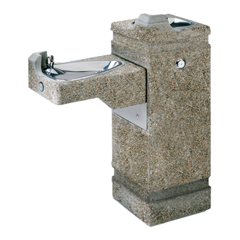
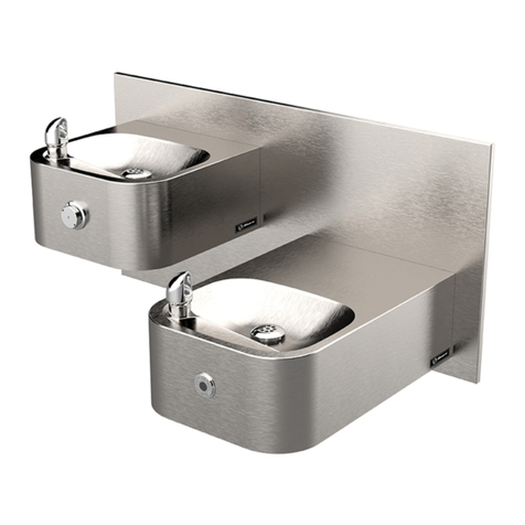
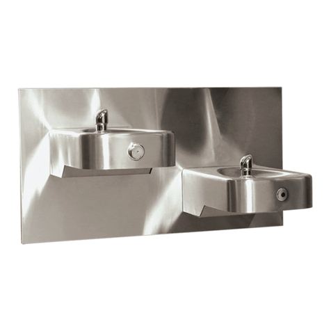
LOCATION OF UNIT: The Model 36XX/36XXFR Bottle Filler / Fountain can be assembled to
be wheelchair accessible. When the right pedestal arm (if applicable) is installed in the high
orientation, the height dimensions shown on the model specification sheet meet current
Federal Americans with Disabilities Act (ADA) wheelchair requirements. When the left
pedestal arm (if applicable) is installed in the highest position, the height dimensions shown
on the model specification sheet meet current ADA standing height requirements. When
installing this unit, local, state and federal (including ADA) codes must be adhered to. If height
other than shown is required, then dimensions must be adjusted accordingly.
SUPPLY LINE: The minimum recommended line size is 1/2“IPS with 30-90 psi (2-6 ATM)
flowing pressure. Where sediment or mineral content is a problem, an inlet filter is
recommended.
PLUMBING CONNECTIONS: Water supply inlet connection is a 3/8“O.D. quick-connect
fitting. Waste outlet is 1-1/2” PVC pipe. Plumbing connections vary depending on how the unit
is configured during assembly. Please consult the installation drawings below for supply and
waste fitting arrangements and assembly for your specific model.
MAINTENANCE: For 36XX models- Periodically clean the pushbutton valve strainer. Refer
to 5874 Series Valve Operation and Maintenance Sheet for more information.
For 36XXFR models- Refer to 6518 Operation and Maintenance Sheet for more information.
INSTALLATION PROCEDURE
Follow the installation procedures outlined in the installation diagrams for your specific model
below. Note: 36XXFR versions must be connected to Haws Model 6518 series freeze resistant
bury valve(s), sold separately. See 6518 installation manual for instructions.
GENERAL NOTES:
1. For all plastic push-in type fitting connections, only connect NSF-61 copper or
plastic tubing. Stainless steel or glass tubing is not recommended. The
following assembly instructions must be followed to ensure a watertight
connection:
a. Cut tubing square and clean.
b. Mark from end of tube the length of insertion (See table below).
c. Push tube into the fitting until it bottoms out.
d. To remove, depress collet and pull tubing out


