Haws H1001.8HPS Guide

H1001.8HPS
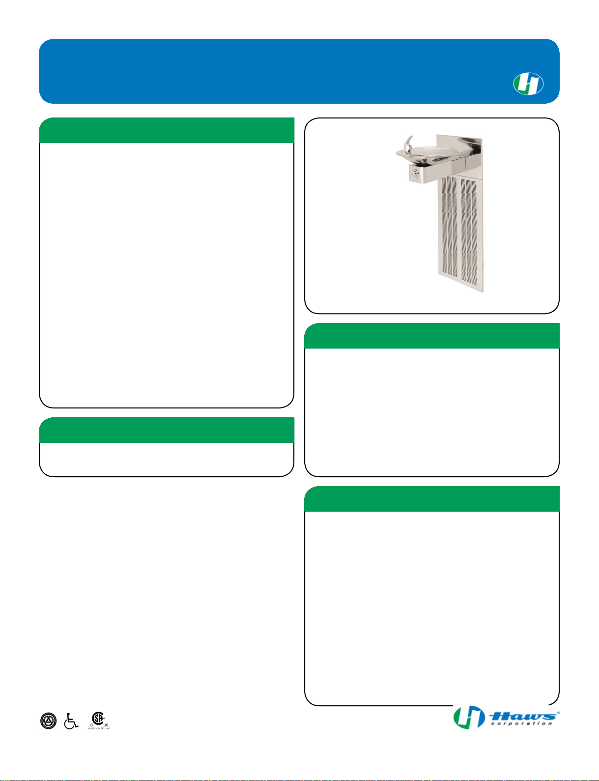
Barrier-Free Wall Mounted Electric Drinking Fountain
Back Panel
Stainless steel back panel helps to protect the wall from
inadvertent splashing, and its decorative satin finish increases
location visibility and completes the fountains attractive
appearance.
Quality Control
Fountain is pre-built and fully water and pressure tested to
ensure no leaks and proper function for reduced installation time
and added peace of mind.
Construction
18 gauge Type 304 Stainless Steel fountain with attractive and
functional swirl bowl design, along with a vandal-resistant
bottom plate provides a long lasting unit with added peace of
mind.
Bubbler Head
Polished chrome-plated brass bubbler head with integral laminar
flow prevents splashing and provides a superior flow pattern.
The integral basin shank and inserted roll pin adds vandal
resistance strength to the design, and the shielded angled
stream orifice produces a steady sanitary source of water.
Push Button
With its patented (Pat.# 6,981,692) push-button valve assembly
which allows for front access stream adjustment as well as
cartridge and strainer access, this fountain offers the ultimate in
ease of maintenance.
FEATURES & BENEFITS
oFilter: Model 6426, 12" x 2", in-line lead removal element that
reduces lead from incoming water supply.
OPTIONS
Model H1001.8HPS electric wall mounted barrier-free drinking
fountain shall include an 18 gauge Type 304 polished stainless
steel finish basin with integral swirl design, push-button operated
valve with front-accessible cartridge and flow adjustment, polished
chrome-plated brass vandal-resistant bubbler head with integral
laminar anti-squirt flow, chrome-plated brass vandal-resistant
waste strainer, vandal-resistant bottom plate, polished stainless
steel finish back panel and louvered intrusion-proof grill, and 1-1/4"
O.D. waste pipe. The R-134a refrigeration system is hermetically
sealed and delivers a minimum of 8 gph (30.3 lph) of water at 50°F
(10°C) cooled from 80°F (26.7°C) inlet water at 90°F (32.2°C)
ambient. 115 Volts, 60Hz, rated watts: 370, full load amps: 5.
SPECIFICATIONS
Perfect for either public or private settings, our stainless steel
electric drinking fountains are a great fit in indoor environments.
This series is precisely mounted, making it a nice addition to any
surrounding. Specifically, this type fountain may be placed in
settings such as: schools, office buildings, shopping malls, and
other indoor environments where there is a demand for a chilled
water source and/or wheel chair access.
Model meets all current Federal Regulations for the disabled
including those in the Americans with Disabilities Act. Electric
water coolers are not recommended or designed for outdoor
applications or enclosed pool areas (chlorine). These conditions
may void warranty. Haws manufactures drinking fountains, electric
water coolers and electric drinking fountains to be lead-free by all
known definitions including ANSI/NSF Standard 61, Section 9,
California Proposition 65, and the Federal Safe Drinking Water Act.
Haws electric water coolers comply with ARI Standard 1010 and
ANSI A117.1, and be listed by Underwriter Laboratories to U.S.
and Canadian standards.
APPLICATIONS
1455 Kleppe Lane | Sparks, NV 89431 | [p] 775.359.4712 | [f] 775.359.7424 | [e] [email protected] | www.hawsco.com | 2 March, 2009
DISCLAIMER: Continued product improvements make specifications subject to change without notice. Check www.hawsco.com for the latest product information and updates.


10/08 Model H1001.8/H1001.8HPS Page 1 of 7
No. 2080246
(
13
)
1455 Kleppe Lane Sparks, NV 89431-6467 (775) 359-4712 Fax (775) 359-7424
HAWS AG Bachweg 3 CH-3401 Burgdorf Switzerland
Haws Mfg. Pte Lt. 2A Sungei Kadet Drive Singapore 729554
Avlis-Avenido Senador, Testonio Vilela 505 Jardim Aeroporto Itu, S.P. 13304-550 Brasil
Model H1001.8/H1001.8HPS
Water Cooler
INSTALLATION, OPERATION
&
MAINTENANCE INSTRUCTIONS
LIMITED WARRANTY
HAWS®warrants that all of its products are guaranteed against defective material or poor
workmanship for a period of one year from date of shipment. HAWS liability under this
warranty shall be discharged by furnishing without charge F.O.B. HAWS Factory any
goods, or part thereof, which shall appear to the Company upon inspection to be of
defective material or not of first class workmanship, provided that claim is made in writing
to company within a reasonable period after receipt of the product. Where claims for
defects are made, the defective part or parts shall be delivered to the Company, prepaid,
for inspection. HAWS will not be liable for the cost of repairs, alterations or replacements,
or for any expense connected therewith made by the owner or his agents, except upon
written authority from HAWS, Sparks, Nevada. HAWS will not be liable for any damages
caused by defective materials or poor workmanship, except for replacements, as provided
above. Buyer agrees that Haws has made no other warranties either expressed or implied
in addition to those above stated, except that of title with respect to any of the products or
equipment sold hereunder and that HAWS shall not be liable for general, special, or
consequential damages claimed to arise under the contract of sale. The drinking fountain
manufactured by HAWS is warranted to function if installation and maintenance
instructions provided are adhered to. The units also must be used for the purpose for
which they were intended.
NO OTHER WARRANTIES EXPRESSED OR IMPLIED ARE AUTHORIZED, PROVIDED
OR GIVEN BY HAWS.
NOTE TO INSTALLER: Please leave this information with the Maintenance Department.
A ground-fault circuit breaker shall be installed
in the branch circuit supplying fountain
equipment. NEC680-51(a).
CAUTION! Prior to making any electrical
connections, verify with a voltmeter that power
from the service panel is off.
SHOULD YOU EXPERIENCE DIFFICULTY WITH THE INSTALLATION OF THIS
MODEL, PLEASE CALL: 1-800-766-5612
FOR PARTS CALL: 1-800-758-9378
(U.S.A. AND CANADA ONLY) MONDAY-THURSDAY: 6:00 A.M. – 4:00 P.M. PST
FRIDAY: 6:00 A.M – 1:00 P.M. PST

10/08 Model H1001.8/H1001.8HPS Page 2 of 7
RECOMMENDED TOOLS: Hack saw, pipe joint sealant, screwdriver, level, 12" adjustable
wrench, 10" pipe wrench, 3/32” and 5/32 “ hex key wrench, 9/16”, 1/2", 7/16” socket wrench or
open end wrench.
LOCATION OF UNIT: The Model H1001.8/H1001.8HPS Cooler is a wheelchair accessible
drinking facility. The height dimensions shown, meet current ADA requirements. When
installing this unit, local, state or federal codes should be adhered to. If height other than
shown is required, then dimensions must be adjusted accordingly.
SUPPLY LINE: The minimum recommended line size is 1/2“IPS with 30-90 psi (2-6 ATM)
flowing pressure. Where sediment or mineral content is a problem, an inlet filter is
recommended.
PLUMBING CONNECTIONS: Inlet is 3/8” O.D. tube. Waste elbow outlet is 1-1/4” O.D. tube.
ELECTRICAL CONNECTIONS: 115VAC, 60HZ, 4.7 AMPS. Chiller wired direct to incoming
line, by others.
PARTS LIST
MODEL PACKAGE QUANTITY ITEMS INCLUDED
MTGFR.SM 1 Mounting Frame
3 #10 Sheet Metal Screws
HCR8 1 Chiller
H1001.8/H1001.8HPS 1 Bowl Assembly
1 Package supply tubing and two (2)
fittings
1 Grille
1 Package of two each-grille attachment
clips, clip nuts, #10 sheet metal screws
and 6-32 screws
4 5/16 -18 retainer nuts
4 5/16 – 18 x 1 hex head screws
1 Waste elbow 1-1/4” O.D.
INSTALLATION PROCEDURE
GENERAL NOTES:
The Model H1001.8/H1001.8HPS Water Cooler assembly requires installation of the mounting
frame as described in Steps 1 - 2, then mounting the fountain bowl assembly as described in
Steps 3 - 6, and finally completing chiller water and electrical connections and starting chiller per
Steps 7 - 11. First check that all required parts are received.
Grounding may cause electrical feedback into the electric drinking fountain causing an
electrolysis, which creates a metallic taste or an increase in the metal content of the
water. This condition can be avoided by using dielectric couplings in the assembly. The
waste line, which is supplied by the installer, should also have a dielectric (plastic)
coupling to completely isolate the assembly from the building plumbing system.
For all plastic push-in type fitting connections; push tubing into fitting until it bottoms
out to ensure a watertight connection. To remove, depress the collet and pull tubing out.

10/08 Model H1001.8/H1001.8HPS Page 3 of 7
INSTALLATION PROCEDURE…
Step 1: Provide wall opening as detailed in Installation Drawing. Frame must be
positioned such that frame flanges overlap and butt against finished wall surface.
Mounting holes are provided for #6 sheet metal screws. After frame is positioned
in wall, swing chiller support tray into position (See Installation Drawing), align
tray holes with holes in frame and fasten with #10 sheet metal screws. Mounted
frame must support 50 pound chiller in addition to fountain weight and user
generated forces.
Step 2: Install waste, supply and electrical lines in locations shown in Installation
Drawing. Waste and supply lines may be installed for either rear or side entry.
Verify proper waste, supply, electrical and frame locations. Use level to verify
horizontal and vertical frame mounting to insure proper bowl drainage.
Step 3: Installation Drawing shows fountain bowl, back panel and grille locations. Unpack
bowl and remove bottom plate using 3/32” hex allen wrench. Install back panel
on frame with narrower edge to bottom. Position nut retainers into mounting
frame and use two 5/16-18x1 hex head screws partially started in outside holes
to support panel. Install bowl/bracket assembly onto panel using four 5/16-18x1
hex head screws hand tightened. See sheet 2 of Installation Drawing for
appropriate bowl mounting pattern to use for this model
Step 4: Remove 1-1/2” IPS outlet elbow from trap (not supplied). Install elbow inside
frame onto waste stub-outs. Reassemble trap “U” bend with inlets centered
behind fountains.
Step 5: Remove slip joint nuts from bottom of fountain waste outlet. Assemble nut over 1-
1/4” O. D. end of waste elbow as supplied by Haws. Assemble waste elbow onto
bowl waste body using seal washer provided and tighten nut hand tight. Measure
vertical distance down to trap inlet and cut the vertical (not supplied) elbow to
length allowing 1/2” minimum for engagement into trap. Mark and similarly cut to
length the horizontal waste elbow. Install elbow and tighten all the slip joint nuts.
Step 6: See Figure 2 for detail section view of side screw grille attachment. Unpack grille
and insert upper lip behind bottom of back panel, align sides and hold up flush to
bottom of back panel. Hold grille against wall and mark centers of grille side slots
on wall. Masking tape may be used to prevent finished wall damage from mark.
Install the “s” clips in mounting frame using #10 sheet metal screws into pre-
drilled holes on lower end of each side of frame. Tighten #10 screw while holding
“s” clips centered on wall marks. Check grille fit by installing grille and partially
tightening #6-23 socket head screws through side of grille. Insure proper panel
and grille alignment, then tighten four 5/16-18x1 hex head screws.
Step 7: Unpack and remove chiller from carton. Remove front panel screws and panel.
Do not remove insulating putty and foam from copper tubes or Styrofoam
insulation from evaporator coil. Remove any inner packing, which may be around
compressor. If applicable, remove junction box cover and electrical knock out on
lower right side of housing. Install fittings (supplied) on chiller inlet and outlet
tubes (See Installation Drawing).

10/08 Model H1001.8/H1001.8HPS Page 4 of 7
INSTALLATION PROCEDURE…
Step 8: Thoroughly flush supply line to remove all foreign matter. Connect 1/2” IPS
supply screwdriver stop (not supplied) to stub-out in wall. Place chiller on chiller
support tray against right hand side, fully to rear, with condenser (open panel)
side facing to front. Install supply, 3/8” O.D. tubing (not supplied), between
screwdriver stop (not supplied) and strainer at chiller inlet. (Cut tubing to proper
length, and follow general notes for proper connection procedure for push-in style
fittings). Tubing insulation is not normally required on inlet side of chiller. Install
insulated tube (supplied) between fountain and chiller outlet. Cut tubes as
required and connect to chiller outlet compression fitting. Open screwdriver stop
wide open while checking for leaks at all connections. Also check waste for
leaks.
Step 9: Adjust bubbler stream height using a small flat-head screwdriver inserted through
a hole in the center of the push button. For increased flow turn clockwise and for
decreased flow turn counterclockwise. If flow problems arise, see
troubleshooting guide for additional instructions to correct problems. Bubbler
stream may lower during short break-in period. Set initial stream height a little
high to minimize or eliminate the need for break-in period readjustment.
Step 10: Verify that electrical power is off and power supply voltage, phase and cycle
match specifications printed on chiller label. In accordance with local codes, wire
directly to incoming lines at internal chiller junction box. Verify that all inner
packing is removed and hand rotate fan blade to verify free rotation. Reattach
chiller front panel. Turn power on and verify that chiller cycles off after water
reaches proper temperature. Finally check for leaks.
Step 11: Install grille and tighten outer side screws. Verify there is chilled water out of
bubbler.
FIGURE 1

10/08 Model H1001.8/H1001.8HPS Page 5 of 7
MAINTENANCE
Step 1: The condenser fins on chiller should be periodically cleaned with brush, air hose
or vacuum cleaner. Care should be taken not to bend or deform the condenser
fins.
Step 2: The chiller temperature control is factory set for 50° F water under normal
conditions. For colder water, adjust control clockwise. For warmer water, turn
counterclockwise. Remove front chiller panel for access to temperature control.
After adjustment allow unit to cycle off before checking outlet water temperature.
TROUBLESHOOTING
PROBLEM REPAIR CHECKLIST
1. Insufficient bubbler flow. 1a. Check that inlet screwdriver stop valve is
in wide-open position.
b. Verify minimum 30 psi flowing supply
pressure.
c. Clean strainer. See 5874 Valve Manual.
d. Adjust valve to increase flow. Use front
adjust screw or see 5874 Valve Manual.
2. Water too warm or cold. a. Adjust chiller temperature control,
clockwise for colder water.
© 2006 Haws®Corporation – All Rights Reserved
HAWS® and other trademarks usedin these materials are the exclusive property of Haws Corporation.


This manual suits for next models
2
Table of contents
Other Haws Plumbing Product manuals
Popular Plumbing Product manuals by other brands

Symmons
Symmons Duro SLC-3612-1.5 Operation & maintenance manual

Officine Gullo
Officine Gullo ACUTAOG03 L Instructions for installation and use

Pfister
Pfister Zeelan LF-042-ZL Quick installation guide

Tylo
Tylo Evolve Corner Tradition manual

Kraus
Kraus Oletto KPF-3101 installation manual

Grohe
Grohe EUROPLUS E 36 207 manual