HBK U9C User manual
U9C
ENGLISH DEUTSCH FRANÇAIS ITALIANO
Mounting Instructions
Montageanleitung
Notice de montage
Istruzioni per il montaggio

Hottinger Brüel & Kjaer GmbH
Im Tiefen See 45
D-64293 Darmstadt
Tel. +49 6151 803-0
Fax +49 6151 803-9100
www.hbkworld.com
Mat.: 7-0111.0012
DVS: A03815 03 YI0 02
06.2022
EHottinger Brüel & Kjaer GmbH
Subject to modifications.
All product descriptions are for general information
only. They are not to be understood as a guarantee of
quality or durability.
Änderungen vorbehalten.
Alle Angaben beschreiben unsere Produkte in allge
meiner Form. Sie stellen keine Beschaffenheits- oder
Haltbarkeitsgarantie dar.
Sous réserve de modifications.
Les caractéristiques indiquées ne décrivent nos
produits que sous une forme générale. Elles
n'impliquent aucune garantie de qualité ou de
durabilité.
Con riserva di modifica.
Tutti i dati descrivono i nostri prodotti in forma
generica e non implicano alcuna garanzia di qualità o
di durata dei prodotti stessi.

U9C
ENGLISH DEUTSCH FRANÇAIS ITALIANO
Mounting Instructions

U9C
TABLE OF CONTENTS
2
TABLE OF CONTENTS
1 Safety instructions 4................................................
2 Markings used 7....................................................
2.1 The marking used in this document 7..................................
3 Scope of supply, accessories and variants 8............................
4 General application instructions 10....................................
5 Structure and mode of operation 11....................................
5.1 Transducer 11.......................................................
5.2 Strain gage covering agent 11.........................................
5.3 Inline amplifier 11....................................................
6 Conditions on site 12.................................................
6.1 Ambient temperature 12..............................................
6.2 Moisture and corrosion protection 12...................................
6.3 Deposits 12.........................................................
7 Mechanical installation 13............................................
7.1 Important precautions during installation 13..............................
7.2 General installation guidelines 13.......................................
7.3 Installing the U9C 14.................................................
7.3.1 Mounting with tension and compression bars 14..........................
7.3.2 Mounting with knuckle eyes 15.........................................
8 Electrical connection 20..............................................
8.1 Connection to measuring amplifier without permanently connected amplifier
module 20..........................................................
8.1.1 General information and connection 20..................................
8.1.2 Cable extension and cable shortening 20................................
8.1.3 EMC protection 21...................................................
8.1.4 TEDS transducer identification 21......................................
8.2 Electrical connection of measuring amplifier with amplifier module 22.......
8.2.1 General information 22...............................................
8.2.2 Connecting the device 23.............................................
8.2.3 Operating the inline amplifier/zeroing the measurement chain 23............


U9C
SAFETY INSTRUCTIONS
4
1 SAFETY INSTRUCTIONS
Intended use
The force transducers in the type series U9C are solely designed for measuring static and
dynamic tensile and compressive forces within the load limits specified by the technical
data for the respective maximum capacities. Any other use is not the intended use.
To ensure safe operation, it is essential to comply with the regulations in the mounting
instructions, the safety requirements listed below, and the data specified in the supplied
technical data sheets. It is also essential to observe the applicable legal and safety regu
lations for the relevant application.
Force transducers are not intended for use as safety components. Please also refer to
the “Additional safety precautions” section. Proper and safe operation of force transduc
ers requires proper transportation, correct storage, setup and mounting, and careful oper
ation.
Load-carrying capacity limits
The information in the technical data sheets must be observed when using the force
transducers. The respective specified maximum loads in particular must never be ex
ceeded. The following limits set out in the technical data sheets must not be exceeded:
SLimit forces
SLateral limit forces
SBending moment and torque
SBreaking forces
SPermissible dynamic loads
Stemperature limits
SElectrical load limits
Please note that when several force transducers are interconnected, the load/force distri
bution is not always uniform.
Use as machine elements
Force transducers can be used as machine elements. When used in this manner, note
that to favor greater sensitivity, force transducers were not designed with the safety fac
tors usual in mechanical engineering. Please refer to the “Load-carrying capacity limits”
section and the specifications.
Accident prevention
The prevailing accident prevention regulations must be taken into account, even though
the breaking force values in the destructive range are well in excess of the full scale
value.

5
U9C
SAFETY INSTRUCTIONS
Additional safety precautions
Force transducers cannot (as passive transducers or as a measurement chain) imple
ment any (safety-relevant) cutoffs. This requires additional components and constructive
measures, for which the installer and operator of the plant is responsible.
In cases where a breakage or malfunction of the force transducer would cause injury to
persons or damage to equipment, the user must take appropriate additional safety pre
cautions that meet at least the applicable safety and accident prevention regulations (e.g.
automatic emergency shutdown, overload protection, catch straps or chains, or other fall
protection).
The electronic processor that processes the measurement signal should be designed so
that failure of the measurement signal cannot lead to secondary failures.
General dangers of failing to follow the safety instructions
Force transducers are state-of-the-art and failsafe. Transducers can give rise to residual
dangers if they are mounted, installed, used and operated inappropriately or by untrained
personnel. Every person involved with setting up, starting up, operating or repairing a
force transducer must have read and understood the mounting instructions and in partic
ular the technical safety instructions. The force transducers can be damaged or de
stroyed by non-designated use of the force transducer or by non-compliance with the
mounting and operating manual, these safety instructions or other applicable safety
regulations (safety and accident prevention regulations of the Employers' Liability Insur
ance Association) when using the force transducers. A force transducer can break, partic
ularly if it is overloaded. The breakage of a force transducer can cause damage to prop
erty or injury to persons in the vicinity of the force transducer.
If force transducers are not used as intended, or if the safety instructions or specifica
tions in the mounting and operating instructions are ignored, it is also possible that a
force transducer may fail or malfunction, with the result that persons may be injured or
property damaged (due to the loads acting on or being monitored by the force trans
ducer).
The scope of supply and performance of the transducer covers only a small area of force
measurement technology, as measurements with (resistive) strain gage sensors require
electronic amplification, and measurement chains require further signal processing.
Equipment planners, installers and operators should always plan, implement and respond
to the safety engineering considerations of force measurement technology in such a way
as to minimize residual dangers. Pertinent national and local regulations must be com
plied with.
Conversions and modifications
The design or safety engineering of the transducer must not be modified without our ex
press permission. Any modification shall exclude all liability on our part for any damage
resulting therefrom.

U9C
SAFETY INSTRUCTIONS
6
Maintenance
The force transducers of the U9C series are maintenance free.
Disposal
In accordance with national and local environmental protection and material recovery and
recycling regulations, old transducers that can no longer be used must be disposed of
separately and not with normal household garbage.
If you require more information about disposal, please contact your local authorities or
the dealer from whom you purchased the product.
Qualified personnel
Qualified personnel means persons entrusted with installing, mounting, starting up and
operating the product who possess the appropriate qualifications for their work.
This includes people who meet at least one of these three requirements:
SAs project personnel, you know and are familiar with the safety concepts of automa
tion technology.
SAs automation plant operating personnel, you have been instructed how to handle the
machinery. You are familiar with the operation of the equipment and technologies
described in this documentation.
SAs a commissioning or service engineer, you have successfully completed training on
the repair of automation plants. Moreover, you are authorized to start up, ground and
label circuits and equipment in accordance with safety engineering standards.
During use, compliance with the legal and safety requirements for the relevant applica
tion is also essential. The same applies to the use of accessories.
The force transducer may only be installed by qualified personnel, strictly in accordance
with the specifications and with the safety requirements and regulations.

7
U9C
MARKINGS USED
2 MARKINGS USED
2.1 The marking used in this document
Important instructions for your safety are specifically identified. It is essential to follow
these instructions in order to prevent accidents and damage to property.
Symbol Significance
WARNING This marking warns of a potentially dangerous situ
ation in which failure to comply with safety require
ments can result in death or serious physical injury.
CAUTION This marking warns of a potentially dangerous
situation in which failure to comply with safety
requirements can result in slight or moderate physical
injury.
Notice This marking draws your attention to a situation in
which failure to comply with safety requirements can
lead to damage to property.
Important This marking draws your attention to important in
formation about the product or about handling the
product.
Tip This marking indicates application tips or other
information that is useful to you.
Information This marking draws your attention to information
about the product or about handling the product.
Emphasis
See …
Italics are used to emphasize and highlight text and
identify references to sections, diagrams, or external
documents and files.

U9C
SCOPE OF SUPPLY, ACCESSORIES AND VARIANTS
8
3 SCOPE OF SUPPLY, ACCESSORIES AND VARIANTS
Scope of supply
SU9C force transducer
SU9C mounting instructions
STest report
Accessories
Description Ordering number
KAB168-5, PUR connection cable with M12 8-pin socket, 5 m long,
free ends on opposite side. For connecting the amplifier module to
the downstream electronics
1-KAB168-5
KAB168-20, PUR connection cable with M12 8-pin socket, 20 m
long, free ends on opposite side. For connecting the amplifier mod
ule to the downstream electronics
1-KAB168-20
Thrust piece EDO9/20kN; suitable for nominal (rated) forces from
0.5 kN … 20 kN
1-EDO9/20kN
Thrust piece EDO9/50kN; suitable for nominal (rated) force 50 kN 1-EDO9/50kN
Equipment variants
All force transducers are available in different versions. The following options are avail
able:
1. Cable
The U9C is equipped with a cable 1.5m long in the standard version. You can also or
der the force transducer with the following cable lengths:
-3 m
-5 m
-6 m
-7 m
-12 m
2. Device plug/electrical connection
We can mount one of the following connectors on the U9C if requested:
-D-SUB connector, 15-pin: 15-pin connector for connection to numerous amplifier
systems, e.g. MGCplus, Scout, MP85, etc.
-D-SUB HD connector: A 15-pin plug for connection to appropriate amplifier systems,
e.g. the HBM QuantumX system

9
U9C
SCOPE OF SUPPLY, ACCESSORIES AND VARIANTS
-3106 PEMV connector (Greenline): For connection to appropriate amplifier sys
tems, e.g. MGCplus with AP03.
-Free ends: Transducer delivered without plugs.
-The force transducer can be ordered with a permanently connected amplifier elec
tronics module which converts the output signal of the force transducer into a 0 ...
10 V signal. This option is only available with 1.5 m and 3 m cable lengths.
-The force transducer can also be ordered with a permanently connected amplifier
electronics module which converts the output signal of the force transducer into a
4…20mA signal. This option is only available with 1.5 m and 3 m cable lengths.
3. TEDS
You can order the force transducer with transducer identification ("TEDS"). TEDS
(Transducer Electronic Data Sheet) allows you to store the transducer data (character
istic values) in a chip that can be read out by a connected measuring device (with an
appropriate amplifier). HBM records the TEDS data before delivery so that no parame
terization of the amplifier is necessary.
TEDS can only be fitted in the plug of the U9C, therefore it is not possible to equip the
"free cable ends" version with TEDS. The versions with permanently connected ampli
fier electronics cannot be connected with the TEDS option.

U9C
GENERAL APPLICATION INSTRUCTIONS
10
4 GENERAL APPLICATION INSTRUCTIONS
The force transducers are suitable for measuring tensile and compressive forces. They
provide highly accurate static and dynamic force measurements and must therefore be
handled very carefully. Particular care must be taken during transportation and installa
tion. Dropping and knocking the transducer may cause permanent damage.
The U9C series force transducers have two external threads into which the forces to be
measured must be applied.
The Specifications section 10 on page 29 lists the permissible limits for mechanical, ther
mal and electrical loading. It is essential to observe these limits when planning the mea
suring set-up, during installation and, ultimately, during operation.
11
U9C
STRUCTURE AND MODE OF OPERATION
5 STRUCTURE AND MODE OF OPERATION
5.1 Transducer
The measuring body is a steel loaded member on which strain gages (SG) are installed.
The influence of a force deforms the measuring body, so there is deformation in places
where the strain gages are installed. The SG are attached so that two are stretched and
two are compressed when a force is applied. The strain gages are wired to form a Wheat
stone bridge circuit. They change their ohmic resistance in proportion to their change in
length and so unbalance the Wheatstone bridge. If there is an excitation voltage, the cir
cuit produces an output signal proportional to the change in resistance and thus also pro
portional to the applied force. The strain gage arrangement is chosen to compensate, as
much as possible, for parasitic forces and moments (e.g. lateral forces and eccentricity
influences), as well as the effects of temperature.
5.2 Strain gage covering agent
To protect the SG, the force transducers have thin cover plates that are welded on the
bottom and, in versions with a nominal (rated) force of up to 200 N, on the top.This
method offers very good protection against environmental conditions so that the U9C
reaches the protection class IP67. In order to retain the protective effect, these plates
must not be removed or damaged in any way.
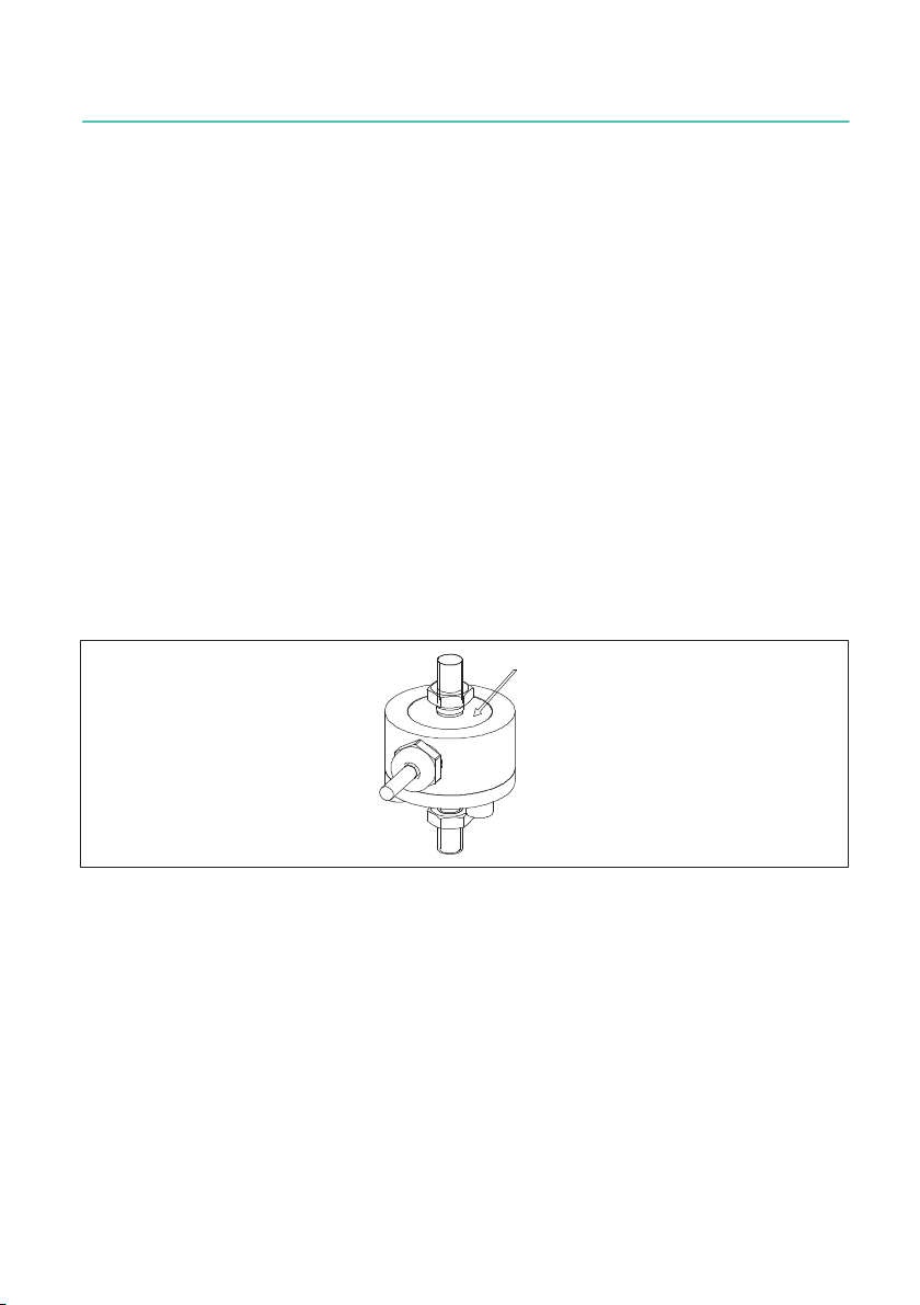
Fig. 5.1 The thin plate on the top side must not be damaged in the variants with
nominal (rated) forces 50N, 100N and 200N; the same applies for the plate on
the bottom of all force transducers.
5.3 Inline amplifier
The sensors can optionally be ordered with an inline amplifier. This amplifier module sup
plies the bridge circuit of the sensors with a suitable supply voltage, and converts the
small output signal of the force transducers with low noise into a 0 ... 10 V voltage signal
(VA1) or a 4 ... 20 mA current signal (VA2). The delivery is then carried out as a measure
ment chain, and the test record describes the correlation between the force input quantity
and the output signal in V or mA.

U9C
CONDITIONS ON SITE
12
6 CONDITIONS ON SITE
U9C series force transducers are made of rustless materials. It is nevertheless important
to protect the transducers from weather conditions such as rain, snow, ice and salt water.
6.1 Ambient temperature
The effects of temperature on the zero signal and on sensitivity are compensated.
To obtain optimum measurement results, comply with the nominal (rated) temperature
range. The compensation of the temperature effect on the zero point is implemented with
great care, but temperature gradients can still have a negative effect on the stability of
zero. Constant or very slowly changing temperatures are therefore best. A radiation
shield and all-round thermal insulation produce noticeable improvements. However, they
must not be allowed to set up a force shunt, i.e. slight movement of the force transducer
must not be prevented.
6.2 Moisture and corrosion protection
The force transducers are hermetically encapsulated and are therefore very insensitive to
moisture. The transducers achieve protection class IP67.
Despite the careful encapsulation, it makes sense to protect the transducers against per
manent exposure to moisture.
The force transducer must be protected against chemicals that could attack the steel.
With stainless steel force transducers, note that acids and all materials which release
ions will in general also attack stainless steels and their welded seams. Should there be
any corrosion, this could cause the force transducer to fail. In this case, appropriate pro
tective measures must be provided.
The housing of the inline amplifiers is made of aluminum and, like the sensor, meets the
requirements of IP67 protection. We recommend protecting the amplifier housing from
sustained weather effects.
6.3 Deposits
Dust, dirt and other foreign matter must not be allowed to accumulate sufficiently to di
vert some of the measuring force around the force transducer, thus invalidating the mea
sured value. (Force shunt). Also remember to lay the connection cable so that no force
shunts are produced at the lower nominal (rated) forces (<1 kN).

13
U9C
MECHANICAL INSTALLATION
7 MECHANICAL INSTALLATION
7.1 Important precautions during installation
SHandle the transducer with care.
SEnsure that the force application parts mounted on the sensor are designed to with
stand the forces to be measured.
SWelding currents must not be allowed to flow over the transducer. If there is a risk
that this might happen, you must use a suitable low-ohm connection to electrically
bypass the transducer. HBM offers the highly flexible EEK ground cable in various
lengths for this purpose, which can be screwed on above and below the transducer.
SMake sure that the transducer is not overloaded.
The cable fastening side of the transducer should always be connected directly with the
rigid customer-side force transfer area. Ensure that the cable is laid so that, where possi
ble, no force shunt is caused by the cable.
WARNING
There is a danger of the transducer breaking if it is overloaded. This can cause danger for
the operating personnel of the system in which the transducer is installed, as well as for
people in the vicinity.
Implement appropriate safety measures to avoid overloads (also see the Specifications
section 10 on page 29) or to protect against resulting dangers.
7.2 General installation guidelines
The forces to be measured must act on the transducer as accurately as possible in the
direction of measurement. Torques, bending moments resulting from lateral force, eccen
tric loading and the lateral forces themselves, may produce measurement errors and de
stroy the transducer if limit values are exceeded.
Eccentric loads can lead to a bending moment load. The bending moment can be calcu
lated by multiplying the applied force by the eccentricity:
Mb= F*e

U9C
MECHANICAL INSTALLATION
14
Fnom Force in direction of measurement, centric
application
Fex Force in direction of measurement, but
applied outside center of force transducer
e Eccentricity, distance between center of
force transducer and an eccentrically applied
force Fex
FQForce applied vertically to direction of
measurement (lateral force)
MbBending moment
MdTorque
Fnom Fex
FQ
Mb
Md
e
Fig. 7.1 Parasitic forces and moments
Notice
During installation and when operating the transducer, please be aware of the maximum
parasitic forces/lateral forces (caused by skewed application), bending moments (caused
by eccentric force introduction) and torques, see Specifications section 10, and the maxi
mum permissible load-carrying capacity of any (customer side) force application parts that
may be used.
Also note the maximum load-carrying capacity of the fittings, tension/compression bars,
bolts and knuckle eyes that are used.
7.3 Installing the U9C
7.3.1 Mounting with tension and compression bars
In this mounting variant, the transducer is mounted on a construction element by means
of tension/compression bars, and can measure tensile and compressive forces. Alternat
ing loads are also correctly recorded if the transducer is mounted without axial play. For
dynamic alternating loads, the upper and lower threaded connectors must be pre-
stressed to above the maximum force to be measured and then locked in place.

15
U9C
MECHANICAL INSTALLATION
1. Installationand locking with initial stress (for dynamic loading):
-Unscrew the locknut and screw on the threaded connector.
-Pre-stress the transducer to 110% operating load in tensile direction. The trans
ducer itself can be used to measure this force
-Hand-tighten the locknut.
-Relieve the load on the transducer.
Notice
If the torque for locking is shunted through the transducer, ensure that the maximum
torque is not exceeded. See specifications.
2. Mounting with locking
Screw on the load application parts and lock with a torque according to the table below.
Notice
As the initial stress also depends on the friction between the locknut and thread, the initial
stress cannot be precisely set correctly with this method. When using the force transducer
under high alternating loads, we therefore recommend installation using method 1 (instal
lation and locking with initial stress).
Nominal (rated) force range Torque
[Nm]
50 N - 1 kN 8
2 kN - 20 kN 40
50 kN 200
7.3.2 Mounting with knuckle eyes
Knuckle eyes prevent the application of torsional moments and, where two knuckle eyes
are used, bending moments, together with lateral and oblique loads. They are particularly
suitable for static and quasi-static measurements. We recommend tension/compression
bars that are pliable for dynamic alternating loads.
Mounting with knuckle eyes is implemented in the same manner for loads a mounting
with tension/compression bars. Knuckle eyes without locking can be used for static and
quasi-static applications.
U9C
MECHANICAL INSTALLATION
16
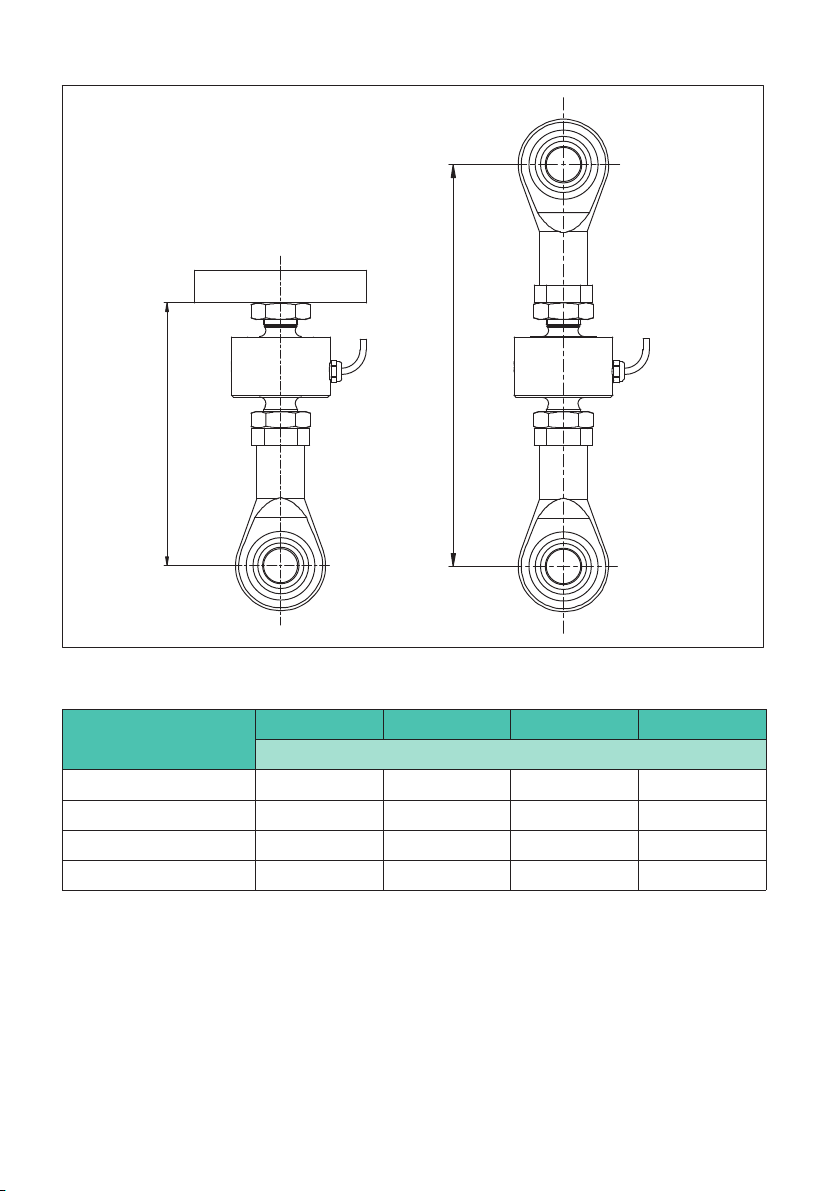
b
a
Fig. 7.2 U9C dimensions when using one or two knuckle eyes.
Nominal (rated) force amin amax bmin bmax
mm
50 … 20 N 55 59 82 86
0.5 … 1 kN 56 61 83 88
2 … 20 kN 79 82 122 125
50 kN 116 116 180 180
Tab. 7.1 Mounting dimensions of the U9C when using knuckle eyes
Notes on mounting with knuckle eyes
1. Shaft diameter
When using a sensor with knuckle eyes mounted on one or both sides, make sure that the
shaft is the right size.

17
U9C
MECHANICAL INSTALLATION
You will find the diameters of the knuckle eyes and shafts and their recommended
tolerances in the table below.
Knuckle eyes Nominal
diameter
Hole fitting
size
Recommended shaft
fitting size
1-Z8/100kg/ZGW 5
H7 g6
1-U9/20kg/ZGWR 10
1-U9a/50kg/ZGW 16
Tab. 7.2 Recommended fitting sizes/tolerances for shaft and hole
Customer’s construction
Customer’s shaft holder
Shaft
Play based on recommended fitting
size, see Tab. 7.2, page 17
Threaded connector for mount
ing on force transducers
Fig. 7.3 Example diagram of installation with knuckle eye
CAUTION
If a shaft with an overly small diameter is used, the bearing of the knuckle eye will be sub
jected to linear load. This subjects the inner bearing shell to excessive load, which can lead
to damage and, if forces are high, can cause the knuckle eye bearing to break.
Select the shaft as recommended in the mounting instructions.

U9C
MECHANICAL INSTALLATION
18
2. Distance between knuckle eye and shaft bearing
The shaft support must allow for suitable play between the knuckle eye and the shaft
bearing.
CAUTION
If there is too much distance between the knuckle eye and the shaft bearing, this generates
bending moments in the shaft, causing it to deform.
This deformations put strain on points of the edges of the inner bearing shell, which can
cause the knuckle eye or shaft to suffer damage or break.
Select the play as recommended in the mounting instructions.
To determine the play between the knuckle eye and the shaft bearing, you can apply the
following rule of thumb:
Shaft diameter Play between knuckle eye and bearing
<30 mm 1/10 of the nominal diameter
Tab. 7.3 Play between knuckle eye and shaft bearing
Based on this, recommendations for the play between the knuckle eye and shaft bearing
are as follows:
Knuckle eye Play between knuckle eye and shaft bearing
1-Z8/100kg/ZGW 0.5mm
1-U9/20kg/ZGWR 1mm
1-U9a/50kg/ZGW 1.6mm
Tab. 7.4 Recommendations for play between knuckle eye and shaft bearing
Table of contents
Languages:
Other HBK Industrial Equipment manuals


Popular Industrial Equipment manuals by other brands

Peter electronic
Peter electronic VersiSafe Speed 27810 Series Assembly instructions

HISAKA
HISAKA UX-005A manual

Group Dynamics
Group Dynamics 2300 Technical manual

SAMES KREMLIN
SAMES KREMLIN REGULEX 5 CC Installation and safety instructions

Numa
Numa Patriot 120 Care & maintenance instructions

Vixen Horns
Vixen Horns VXO8330/4901B installation guide


 operating instructions")
Datcon
Datcon DT1102 M (PS) operating instructions

Microcanner
Microcanner MC FLEX Operating instructions manual

Wavetronix
Wavetronix Click 223 quick start guide

KTR-Group
KTR-Group BoWex M Series Operating & assembly instructions

Fein
Fein AGSZ18-280 BL instruction manual

Moeller
Moeller DILM32-XTE Series installation instructions