HBK U3 User manual

U3
ENGLISH DEUTSCH FRANÇAIS
Mounting Instructions
Montageanleitung
Notice de montage

Hottinger Brüel & Kjaer GmbH
Im Tiefen See 45
D-64293 Darmstadt
Tel. +49 6151 803-0
Fax +49 6151 803-9100
www.hbkworld.com
Mat.: 7-2001.2113
DVS: A02113 02 Y00 04
04.2022
EHottinger Brüel & Kjaer GmbH
Subject to modifications.
All product descriptions are for general information
only. They are not to be understood as a guarantee of
quality or durability.
Änderungen vorbehalten.
Alle Angaben beschreiben unsere Produkte in allge
meiner Form. Sie stellen keine Beschaffenheits- oder
Haltbarkeitsgarantie dar.
Sous réserve de modifications.
Les caractéristiques indiquées ne décrivent nos
produits que sous une forme générale. Elles
n'impliquent aucune garantie de qualité ou de
durabilité.
U3
ENGLISH DEUTSCH FRANÇAIS
Mounting Instructions

U3
TABLE OF CONTENTS
2
TABLE OF CONTENTS
1 Safety instructions 3................................................
2 Markings used 5....................................................
2.1 The markings used in this document 5.................................
2.2 Symbols on the product 5............................................
3 Scope of supply 6...................................................
4 Application information 7............................................
5 Structure and mode of operation 8....................................
5.1 Measuring element 8................................................
5.2 Housing 8.........................................................
6 Conditions on site 9.................................................
6.1 Ambient temperature 9..............................................
6.2 Moisture 9.........................................................
6.3 Deposits 9.........................................................
7 Mechanical installation 10............................................
7.1 Important measures for installation 10..................................
7.2 General installation guidelines 10.......................................
7.3 Installation for tensile loading/compressive loading 11....................
7.3.1 Installation without adapter 11.........................................
7.3.2 Installation with adapter and knuckle eye 12.............................
7.3.3 Installation with two knuckle eyes 14....................................
8 Electrical connection 19..............................................
8.1 Instructions for cabling 19.............................................
9 Specifications (VDI/VDE2638) 21......................................
10 Dimensions 23......................................................

3
U3
SAFETY INSTRUCTIONS
1 SAFETY INSTRUCTIONS
Use in accordance with the regulations
Force transducers in the U3 range are designed for force measurements on test
benches/in press‐fit devices/test devices/pressing. Use for any additional purpose shall
be deemed to be not in accordance with the regulations.
In the interests of safety, the transducer should only be operated as described in the
Mounting Instructions. It is also essential to observe the appropriate legal and safety
regulations for the application concerned during use. The same applies to the use of
accessories.
The transducer is not a safety element within the meaning of its use as intended. Proper
and safe operation of this transducer requires proper transportation, correct storage,
assembly and mounting and careful operation and maintenance.
General dangers due to non‐observance of the safety instructions
The U3 force transducer corresponds to the state of the art and is fail‐safe.
The transducers can give rise to residual dangers if they are inappropriately installed and
operated by untrained personnel.
Everyone involved with the installation, commissioning, maintenance or repair of a force
transducer must have read and understood the Mounting Instructions and in particular
the technical safety instructions.
Residual dangers
The scope of supply and performance of the transducer covers only a small area of force
measurement technique. In addition, equipment planners, installers and operators should
plan, implement and respond to the safety engineering considerations of force measure
ment technique in such a way as to minimise residual dangers. Prevailing regulations
must be complied with at all times. There must be reference to the residual dangers con
nected with force measurement technique.

U3
SAFETY INSTRUCTIONS
4
Conversions and modifications
The transducer must not be modified from the design or safety engineering point of view
except with our express agreement. Any modification shall exclude all liability on our part
for any damage resulting therefrom. Mounting and removing the adapter in accordance
with Chapter 7 excluded.
Qualified personnel
This instrument is only to be installed by qualified personnel strictly in accordance with
the technical data and with the safety rules and regulations which follow. It is also
essential to observe the appropriate legal and safety regulations for the application
concerned. The same applies to the use of accessories.
Qualified personnel means persons entrusted with the installation, fitting, commissioning
and operation of the product who possess the appropriate qualifications for their func
tion.
Conditions on site
Protect the transducer from damp and weather influences such as rain, snow, etc.
Maintenance
The U3 force transducer is maintenance free. We recommend to calibrate the force
transducer at regular intervals.
Accident prevention
Although the specified nominal force in the destructive range is several times the full
scale value, the relevant accident prevention regulations from the trade associations
must be taken into consideration.
5
U3
MARKINGS USED
2 MARKINGS USED
2.1 The markings used in this document
Important instructions for your safety are specifically identified. It is essential to follow
these instructions in order to prevent accidents and damage to property.
Symbol Significance
WARNING This marking warns of a potentially dangerous situ
ation in which failure to comply with safety require
ments can result in death or serious physical injury.
CAUTION This marking warns of a potentially dangerous
situation in which failure to comply with safety
requirements can result in slight or moderate physical
injury.
Notice This marking draws your attention to a situation in
which failure to comply with safety requirements can
lead to damage to property.
Important
This marking draws your attention to important in
formation about the product or about handling the
product.
Tip
This marking indicates application tips or other
information that is useful to you.
Information
This marking draws your attention to information
about the product or about handling the product.
Emphasis
See …
Italics are used to emphasize and highlight text and
identify references to sections, diagrams, or external
documents and files.
2.2 Symbols on the product
Statutory marking requirements for waste disposal
National and local regulations regarding the protection of the
environment and recycling of raw materials require old equip
ment to be separated from regular domestic waste for disposal.
For more detailed information on disposal, please contact the
local authorities or the dealer from whom you purchased the
product.

U3
SCOPE OF SUPPLY
6
3 SCOPE OF SUPPLY
S1 U3 force transducer
S1 U3 Mounting Instructions
STest report
Accessories (not included in the scope of supply)
S'Complete adapter' for knuckle eye mounting:
0.5-10 kN Adapter with four M5x12 and four M5x16 screws
Order no. 2-9289.1956
20 kN Adapter with four M10x25 and four M10x30 screws
Order no. 2-9289.1957
50 kN Adapter with eight M10x25 and eight M10x30 screws
Order no. 2-9289.1958
100 kN Adapter with eight M10x25 and eight M10x30 screws each
Property class 12.9. galvanized Order no. 2-9289.2280
SKnuckle eye ZGUW for:
0.5-10 kN Order no. 1-U2A/1 t/ZGUW
20 kN Order no. 1-U2A/2 t/ZGUW
50 kN Order no. 1-U2A/5 t/ZGUW
100 kN Order no. 1-Z4/100 kN/ZGUW

7
U3
APPLICATION INFORMATION
4 APPLICATION INFORMATION
Force transducers of the U3 type series are suitable for measuring tensile and
compressive forces. They measure static and dynamic forces extremely accurately and
therefore require careful handling. You must take particular care when transporting and
installing the devices. If you knock or drop the transducers, this could permanently
damage them.
The housing provides an elaborate seal to protect the sensitive strain gauge applications
and it is essential that this is preserved. You must be particularly careful with the base of
the housing, as this is extremely thin.
The limits for the permissible mechanical thermal and electrical stresses are stated in the
Specifications. It is essential that these are taken into consideration in planning the
measuring set‐up, during installation and finally, during operation.
U3
STRUCTURE AND MODE OF OPERATION
8
5 STRUCTURE AND MODE OF OPERATION
5.1 Measuring element
The measuring element is a measuring spring made from stainless steel, to which strain
gauges (S/G) are applied. The S/Gs are arranged so that four of them can be strained
and the other four compressed when the transducer reacts to a force.
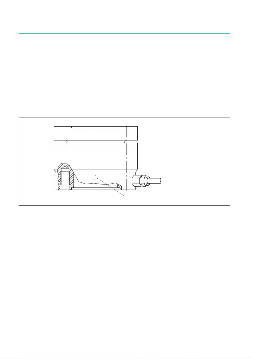
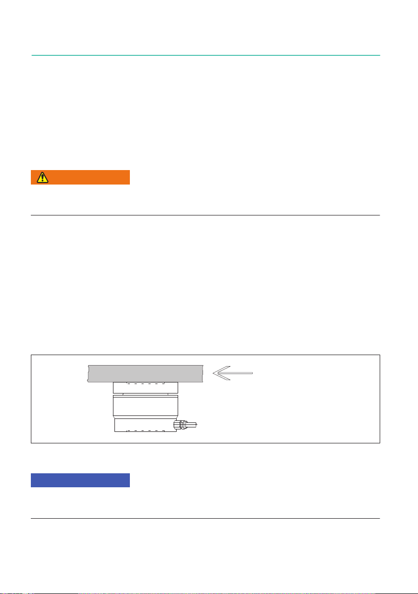
5.2 Housing
The housing with the integrated measuring spring is completed underneath by an
attached base. This base is extremely thin and must not be loaded centrally (see Page
11). It should be protected against mechanical damage.
Pressure compensation hole
Fig. 5.1 Position of housing base
9
U3
CONDITIONS ON SITE
6 CONDITIONS ON SITE
6.1 Ambient temperature
The effects of temperature on the zero signal and on the sensitivity are compensated. To
achieve optimal measurement results the nominal temperature range must be main
tained. Temperature‐induced measurement errors are caused by heating (e.g. radiant
heat) or cooling on one side. A radiation barrier and all‐round thermal insulation will pro
duce a marked improvement, but should not form a force shunt.
6.2 Moisture
Extreme humidity or a tropical climate should be avoided if this means that the classified
limit values are exceeded (degree of protection IP65 under DIN EN 60529).
Notice
Moisture must not be allowed to penetrate the free end of the connection cable or get into
the pressure compensation hole.
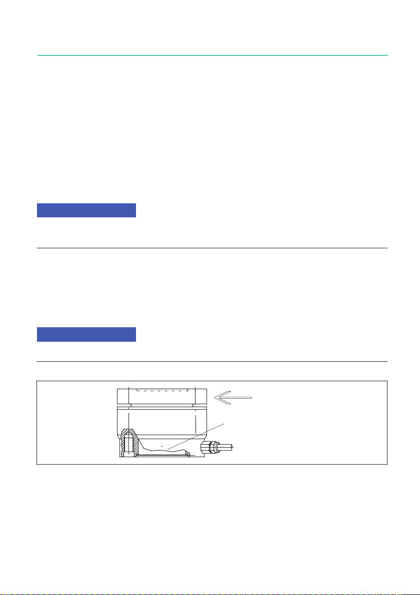
6.3 Deposits
Dust, dirt and other foreign bodies must not be allowed to accumulate such that they
divert part of the measured force onto the housing and so falsify the measured value
(force shunt).
Notice
Foreign bodies must not be allowed to clog the gap beneath the flange surface.
Pressure compensation hole
U3
MECHANICAL INSTALLATION
10
7 MECHANICAL INSTALLATION
7.1 Important measures for installation
SHandle the transducer with care.
SDo not overload the transducer.
SWelding currents must not be allowed to flow over the transducer. If there is a risk
that this might happen, you must use a suitable low‐ohm connection to electrically
bypass the transducer. HBM, forexample, provides the highly flexible EEK ground
cable, which can be screwed on, both above and below the transducer.
WARNING
If there is a risk of breakage through overload on the transducer and thus a risk to persons,
additional safety measures are to be taken.
7.2 General installation guidelines
The direction of measurement in which the forces work should be as much towards the
transducer as possible. Torsion and bending moments, eccentric loading and transverse
forces may result in measurement errors and if the limit values are exceeded, could
destroy the transducer. The U3 has a centering aid for centric force application. Refer to
the drawing in section 10 "Dimensions", page 23.
The transducer can take up 100 % (80 % at 50 kN, 50 % at 100 kN) of its nominal force as
transverse force by reference to a force introduction point on the force‐introduction
surface (see diagram Fig. 7.1), without losing its mechanical competence.
Transverse force
Fig. 7.1 Transverse force introduction
Notice
In the case of transducers of nominal forces 20 kN, 50 kN and 100 kN, the base area is not
flat.
11
U3
MECHANICAL INSTALLATION
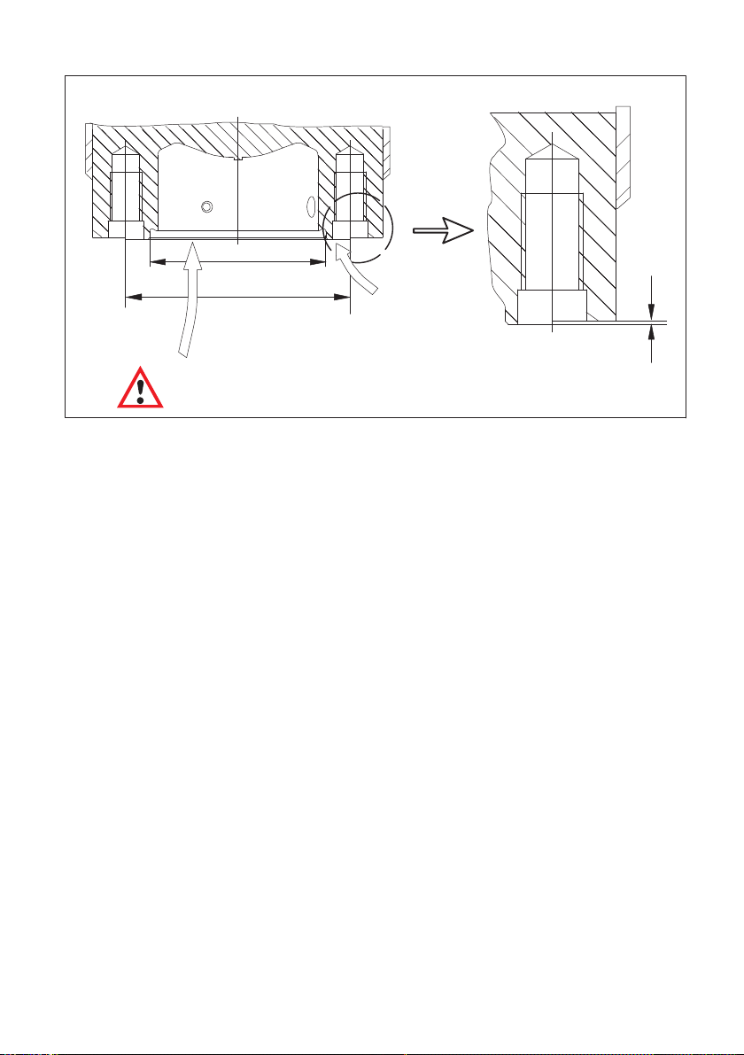
55H8
∅70"0.1 Force must only
be introduced here
0.5
Do not load centrally here.
Center the U3 over diameter 55H8.
Nominal force 20 kN, 50 kN and 100 kN
Fig. 7.2 Base of the U3
7.3 Installation for tensile loading/compressive loading
7.3.1 Installation without adapter
The transducer is screwed directly (by flange or base) on to an existing structural
element (e.g. profile, cover, plate). This type of installation enables the transducers to
measure axial forces in the tensile force and compressive force directions. Alternating
loads can also be recorded perfectly. The transducer must be installed without axial play
for this. For dynamic sustained loading, the top and bottom threaded connectors must be
prestressed by lock nuts to above the maximum load.
U3
MECHANICAL INSTALLATION
12
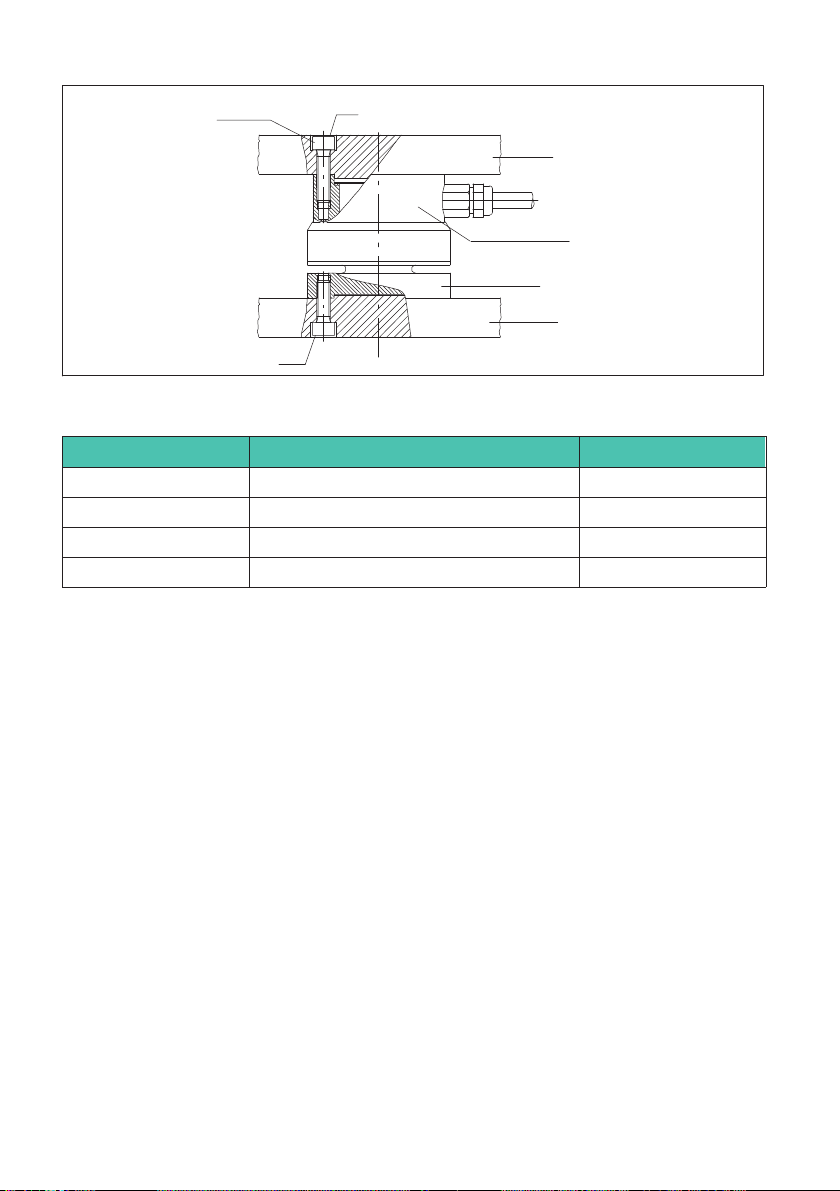
drawing offset
by 45° or 22.5°
MA
MA
provided by customer
provided by customer
Flange
base
Fig. 7.3 Installation for compressive loading
Nominal force (kN) Starting torque MA(NVm) Thread1)
0.5 - 10 54 x M5
20 40 4 x M10
50 40 8 x M10
100 94 8 x M10 2)
1) Take note of the thread depth (see Dimensions, Page 23)
2) 12.9 DIN912 galvanized
HBM supplies knuckle eyes as mounting accessories for transducers of the U3 type
series. Knuckle eyes are suitable for use during quasi‐static loading (10 Hz alternating
loads). In the case of dynamic loading at a higher frequency, you should use flexible
tension bars. Knuckle eyes prevent the introduction of torsional moments and when 2
knuckle eyes are used, stop bending moments and transverse and angular loading being
introduced in the transducers.
7.3.2 Installation with adapter and knuckle eye
If the transducer is to be tensile force loaded, it can be mounted with an adapter (HBM
accessory) and a knuckle eye. There is a center hole (34H8 mm or 55H8 mm, effective
depth approx. 1 mm) on both sides of the transducer.
13
U3
MECHANICAL INSTALLATION
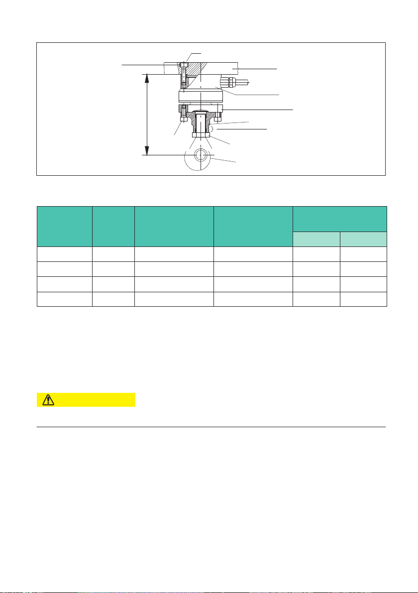
H
drawing offset
by 45° or 22.5°
M2 (MA)
provided by customer
lock nut, MB
ZGUW/1 - 5T/100 kN
M1 (MA)
adapter
flat
base
flange
Fig. 7.4 Installation for tensile loading
Nominal
force (kN)
HMax
(mm)
Starting torque
MA(NVm)
Starting torque
MB(NVm)
Screws for adapter
mounting
M1 M2
0.5 - 10 108 5 60 M5x12 M5
20 170 40 300 M10x25 M10
50 180 40 500 M10x25 M10
100 187 94 1000 M10x25 M10
Attaching the knuckle eye
SScrew the correct adapter (dependent on nominal force!) to the U3 (please note screw
length, screw quality A2-70, at 100 kN. 12.9 DIN912, galvanized)
STurn the lock nut back as far as the eye
SScrew the knuckle eye into the adapter as far as the stop
CAUTION
Do not apply force to the transducer flange.
SUnscrew knuckle eye 1 to 2 turns and align
SLoad eye with nominal load
STighten lock nut (MB, lock using the flat of the adapter)
U3
MECHANICAL INSTALLATION
14
CAUTION
When locking with the lock nut, under no circumstances let the torque be transmitted
through the transducer.
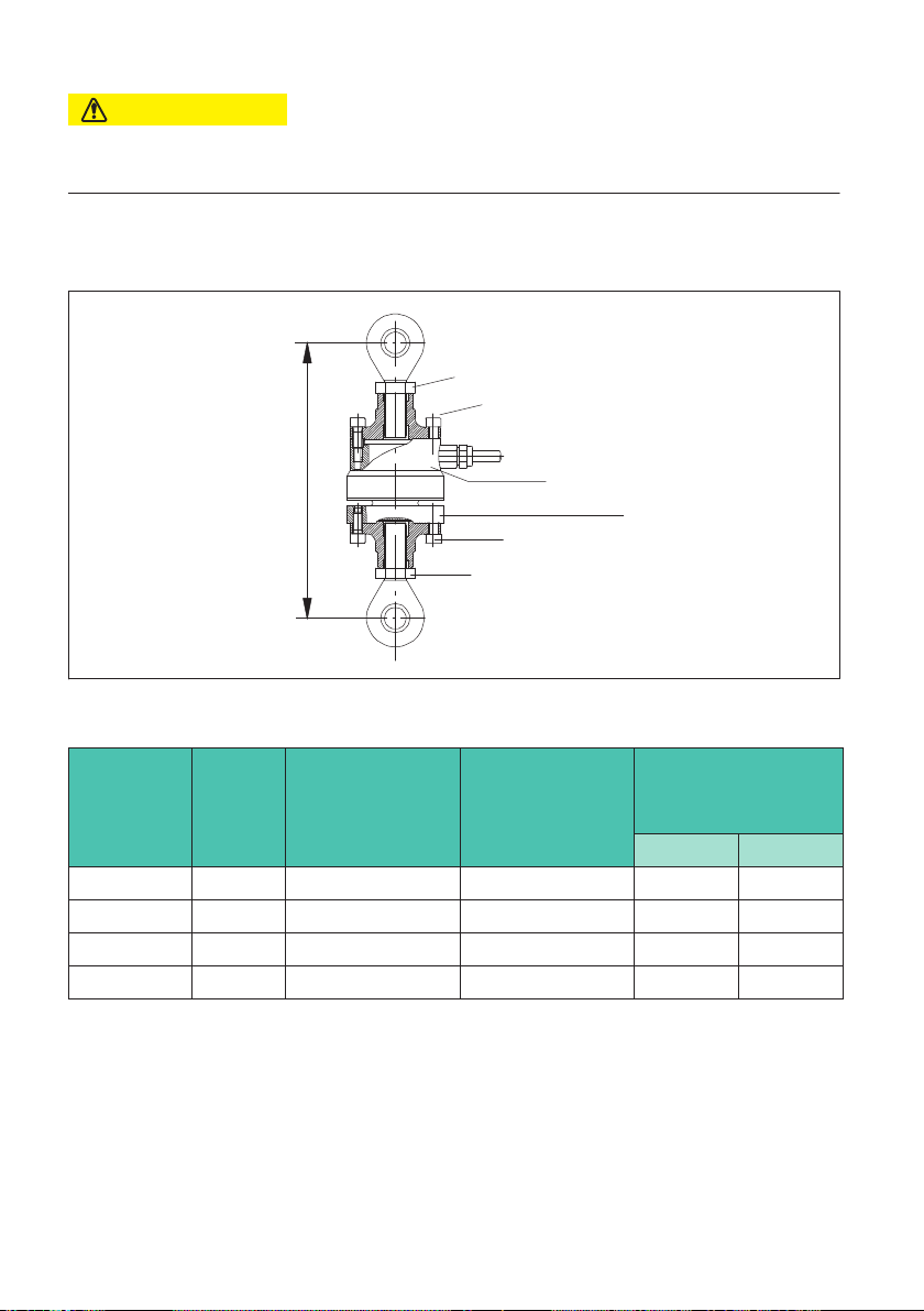
7.3.3 Installation with two knuckle eyes
H
M2 (MA)
MB
MB
M1 (MA)
base
flange
Fig. 7.5 Installation for tensile loading with two knuckle eyes
Nominal
force (kN)
H (mm) Starting torque
MA(NVm)
Starting torque
MB(NVm)
Screws for adapter
mounting
M1 M2
0.5 - 10 153 5 60 M5x12 M5x16
20 232 40 300 M10x25 M10x30
50 256 40 500 M10x25 M10x30
100 300 94 1000 M10x25 M10x30
Attaching the knuckle eye
SScrew the correct adapter (dependent on nominal force!) to the U3 (please note screw
length)
STurn the lock nut back as far as the eye
SScrew the knuckle eye into the adapter as far as the stop

15
U3
MECHANICAL INSTALLATION
CAUTION
Do not apply force to the transducer flange.
SUnscrew knuckle eye 1 to 2 turns and align
SLoad eye with nominal load
STighten lock nut (MB, lock using the flat of the adapter)
CAUTION
When locking with the lock nut, under no circumstances let the torque be transmitted
through the transducer.
Notes on mounting with two knuckle eyes
1. Shaft diameter
When using a sensor with knuckle eyes mounted on one or both sides, make sure that the
shaft is the right size.
You will find the diameters of the knuckle eyes and shafts and their recommended
tolerances in the table below.
Knuckle eyes Nominal
diameter
Hole fitting
size
Recommended shaft
fitting size
1-U2A/1t/ZGUW 12
H7 g6
1-U2A/2t/ZGUW 20
1-U2A/5t/ZGUW 25
1-Z4/100kN/ZGUW 30
Tab. 7.1 Recommended fitting sizes/tolerances for shaft and hole

U3
MECHANICAL INSTALLATION
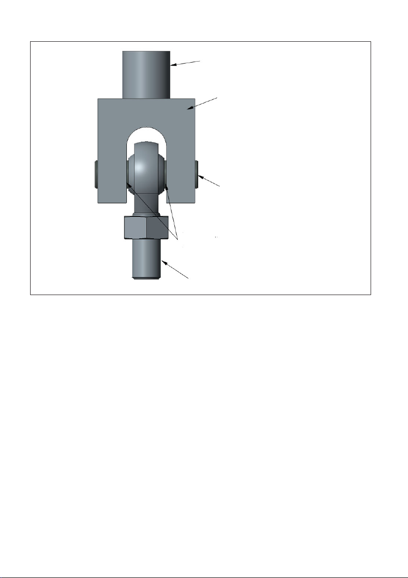
16
Customer's construction
Customer's shaft holder
Shaft
Play based on recommended fitting
size, see Tab. 7.1, page 15
Threaded connector for mounting
on force transducers
Fig. 7.6 Example diagram of installation with knuckle eye
CAUTION
If a shaft with an overly small diameter is used, the bearing of the knuckle eye will be
subjected to linear load. This subjects the inner bearing shell to excessive load, which can
lead to damage and, if forces are high, can cause the knuckle eye bearing to break.
Select the shaft as recommended in the mounting instructions.
2. Distance between knuckle eye and shaft bearing
The shaft support must allow for suitable play between the knuckle eye and the shaft
bearing.

17
U3
MECHANICAL INSTALLATION
CAUTION
If there is too much distance between the knuckle eye and the shaft bearing, this generates
bending moments in the shaft, causing it to deform.
This deformation puts strain on points of the edges of the inner bearing shell, which can
cause the knuckle eye or shaft to suffer damage or break.
Select the play as recommended in the mounting instructions.
To determine the play between the knuckle eye and the shaft bearing, you can apply the
following rule of thumb:
Shaft diameter Play between knuckle eye and bearing
≤30mm 1/10 of the nominal diameter
Tab. 7.2 Rule of thumb for determining play between knuckle eye and shaft bearing
Based on this, recommendations for the play between the knuckle eye and shaft bearing
are as follows:
Knuckle eye Play between knuckle eye and shaft bearing
1-U2A/1t/ZGUW 1.2mm
1-U2A/2t/ZGUW 2mm
1-U2A/5t/ZGUW 2.5mm
1-Z4/100kN/ZGUW 3mm
Tab. 7.3 Recommendations for play between knuckle eye and shaft bearing
U3
MECHANICAL INSTALLATION
18
Customer's construction
Customer's shaft holder
Recommended play,
see Tab. 7.3, page 17
Threaded connector for mounting
on force transducers
Shaft
Fig. 7.7 Example diagram of installation with knuckle eye
3. Shaft surface quality and hardness
The recommended surface roughness is ≤10 μm.
The shaft must have a minimum hardness of 50 HRC.
Table of contents
Languages:
Other HBK Industrial Equipment manuals


Popular Industrial Equipment manuals by other brands


ASTEC
ASTEC JCI LS Series Operation and Service Manual and Parts Book

Bomar
Bomar Extend Series operating instructions

R&M
R&M FO Field Patch set installation guide

schmersal
schmersal MZM 100 AS operating instructions

PCB Piezotronics
PCB Piezotronics ICP 320C15 Installation and operating manual

Toro
Toro 110-5076 installation instructions

WALTERSCHEID
WALTERSCHEID FK96 Repair instructions

FLO-DYNAMICS
FLO-DYNAMICS TTCF-9B Quick start instructions

Aerotech
Aerotech HexGen HEX500-350HL Hardware manual

TriangleTube
TriangleTube MAXI-FLO MF 350 PT Series Installation and maintenance manual

Pronomic
Pronomic Squeeze&Turn 19472 user manual

MIYAWAKI
MIYAWAKI AG11 user manual