HBK PMX User manual
PMX
ENGLISH DEUTSCH
Quick Start Guide
Kurzanleitung

Hottinger Brüel & Kjaer GmbH
Im Tiefen See 45
D-64293 Darmstadt
Tel. +49 6151 803-0
Fax +49 6151 803-9100
www.hbkworld.com
Mat.: 7-2001.3259
DVS: A03259 05 X00 02
04.2023
EHottinger Brüel & Kjaer GmbH
Subject to modifications.
All product descriptions are for general information
only. They are not to be understood as a guarantee of
quality or durability.
Änderungen vorbehalten.
Alle Angaben beschreiben unsere Produkte in allge
meiner Form. Sie stellen keine Beschaffenheits- oder
Haltbarkeitsgarantie dar.

PMX
ENGLISH DEUTSCH
Quick Start Guide

PMX
TABLE OF CONTENTS
2
TABLE OF CONTENTS
1 Safety instructions 3................................................
2 Purpose of the manual 3.............................................
3 Symbols on the device 4.............................................
4 Mounting/Dismounting/Replacing 5...................................
4.1 Assembly tools and tightening torques 5...............................
4.2 Support rail mounting 6..............................................
4.3 Mounting the wall bracket 9..........................................
4.4 Installing cable fastening plates (optional) 11............................
5 Quick start 12.......................................................
5.1 Preparing the measurement system 12..................................
5.1.1 Connecting transducers 12............................................
5.1.2 Connecting the power supply 15........................................
5.1.3 Connecting to a PC 15................................................
5.1.4 Configuring the PMX 17...............................................
5.2 Typical operating sequence (measurement example) 18...................
5.3 Firmware update 23..................................................

3
PMX
SAFETY INSTRUCTIONS
1 SAFETY INSTRUCTIONS
Important
Please follow the safety instructions in the PMX Operating Manual and in the separate
"Safety Instructions" document (enclosed with the device).
2 PURPOSE OF THE MANUAL
This Quick Start Guide sets out the key points when mounting a PMX device and connect
ing it to a PC, making it easy for you to start gathering measurement results with your
PMX.
It also provides a concrete example of setup with commonly used transducer types.
Important
This Quick Start Guide does not replace the detailed PMX Operating Manual.
The information provided in this Quick Start Guide is expanded on in greater detail in:
Sthe Operating Manual for the PMX Measuring Amplifier System
Sthe PMX web server online Help
PMX
SYMBOLS ON THE DEVICE
4
3 SYMBOLS ON THE DEVICE
Symbol Meaning
The supply voltage must be between 10 and 30VDC.
Read and follow the instructions given in the operating
manual.
CE mark
With the CE mark, the manufacturer guarantees that the prod
uct complies with the requirements of the relevant EC direc
tives (the Declaration of Conformity can be found on the HBM
website HBM www.hbm.com under HBMdoc).
Statutory waste disposal mark
Statutory marking of compliance with emission limits in
electronic equipment supplied to China
CODESYS is a software platform for programmable logic
controllers. The license for CODESYS is already implemented
in WG001 basic housings.

5
PMX
MOUNTING/DISMOUNTING/REPLACING
4 MOUNTING/DISMOUNTING/REPLACING
4.1 Assembly tools and tightening torques
Mounting Required tool Tightening
torque
Fastening the rail clip to the support rail
M 5 hexagon socket screw
Hexagon socket wrench
a.f. 2.5 1.0 … 1.2Nm
Fastening the DIN rail clip to the housing
M 5 hexagon socket screw
Hexagon socket wrench
a.f. 3 3Nm
Fastening the plug-in card
Torx screws M2.5
Torx screwdriver
TX8 0.5 … 0.6Nm
Fastening the wall mount kit
M 4 hexagon socket screw
Hexagon socket wrench
a.f. 3 1.5 … 2Nm
Fastening the side panels
M3 Torx screws
Torx screwdriver
TX10 0.8 … 1Nm
Grounding screw on the PMX
M4 Torx screws
Torx screwdriver
TX20 1.5 … 2Nm
Cable fastening plates
M4 hexagon socket screw
Hexagon socket wrench
a.f. 3 1.5 … 2Nm
PMX
MOUNTING/DISMOUNTING/REPLACING
6
4.2 Support rail mounting
1
2
3
4
Hexagon
socket screw
a.f. 3 mm
75 mm
3
B
A
C
D
Fig. 4.1 Mounting on a support rail
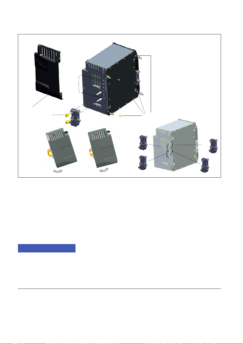
1. Loosen the four rear panel screws (Torx Tx10) (1).
2. Push the side panels forward (2).
3. Screw on the support rail mounting (3) (about 5Nm). Four positions (Ato D) are op
tionally possible (two positions for 7.5 mm rail).
4. Screw the side panels (2) back on.
5. Attach the PMX to the support rail (4).
Notice
Device damage by dropping the PMX due to difficulty of attaching/detaching the PMX.
HBM recommends using a DIN support rail (DIN EN 60715) with a height of 15 mm. When
using a smaller support rail (7.5 mm high), it should be packed, to make it easy to attach/
detach the PMX.
The 7.5 mm support rail can only be used in the top two positions (A and B).
7
PMX
MOUNTING/DISMOUNTING/REPLACING
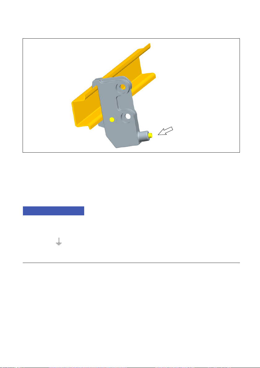
Fastening the support rail mounting (rail clip) to the support rail
Hexagon socket
screw
a.f. 2.5 mm
Fig. 4.2 Fastening the rail clip
On delivery, the self-locking (2.5 mm) hexagon socket screws are unscrewed as far as
the stop.
uClamp on the support rail mounting (rail clip).
uHand-tighten the self-locking hexagon socket screw.
Notice
Device damage caused by electromagnetic irradiation of external devices. Faulty measure
ments due to electromagnetic irradiation from other devices.
To ensure sufficient grounding of the PMX, the support rail must be connected to func
tional ground .
Both the support rail and the PMX must be free of paint and dirt at the mounting location.
uConnect the PMX housing to ground via the grounding screw.

PMX
MOUNTING/DISMOUNTING/REPLACING
8
Dimensions and mounting instructions
200
141
200
122
variable
141*)
min. 25***)
133.5**)
*) Height of support rail 15 mm
**) Height of support rail 7.5 mm
***) Min. dimension: Plug plus sensor cable
NOTE:
To ensure sufficient ventilation/cooling, a 2 cm gap must be maintained above and below
neighboring devices. Dimensions in mm.
Fig. 4.3 Dimensions
9
PMX
MOUNTING/DISMOUNTING/REPLACING
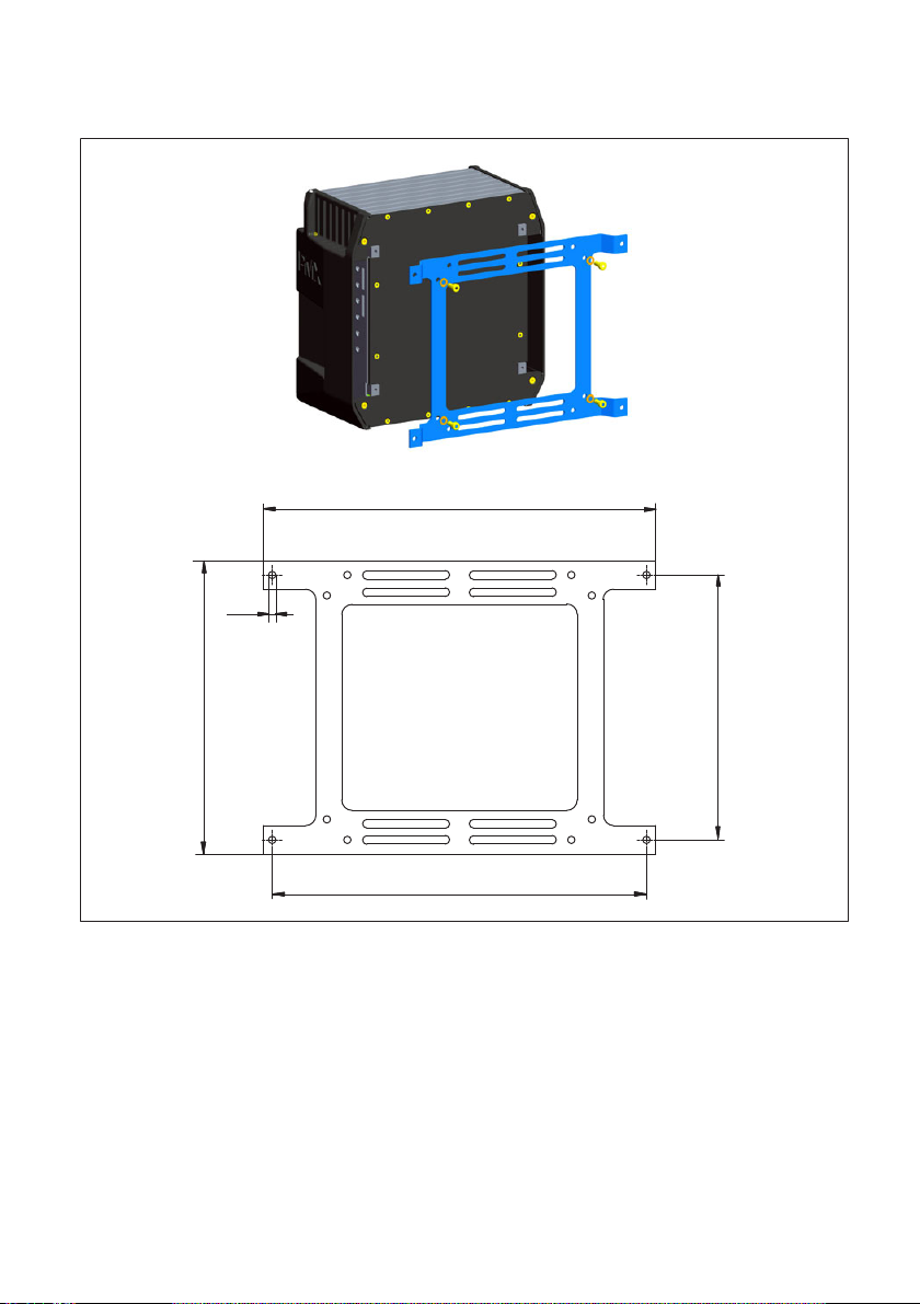
4.3 Mounting the wall bracket
1
225
215
152
4.3
168.5
Dimensions in mm
Fig. 4.4 Mounting on a wall
1. Attach the wall bracket to the back of the PMX by the supplied M4 screws (1).

PMX
MOUNTING/DISMOUNTING/REPLACING
10
Screw
M4
Screw
M4
Screw
M4
Screw
M4
Grounding screw
(Torx TX20)
Fig. 4.5 Wall-mounting
2. Screw the complete unit to the wall. The hole diameter is 4 mm.
Notice
Device damage caused by electromagnetic irradiation of external devices. Faulty measure
ments due to electromagnetic irradiation from other devices.
The housing must also be connected to functional ground when wall-mounted .
uConnect the PMX housing to ground via the grounding screw.

11
PMX
MOUNTING/DISMOUNTING/REPLACING
4.4 Installing cable fastening plates (optional)
Fig. 4.6 PMX with cable holder
To ensure that cables running from and to the PMX are fastened securely and reliably, an
optional plate can be secured to the top and bottom of the PMX mainframe to fasten the
cables using two M4 hexagon socket screws for each plate.
Holes in the plate can be used to fasten the cables using cable ties.
200
250
158
23 28
25
15°
2
122
Dimensions in mm

PMX
QUICK START
12
5 QUICK START
5.1 Preparing the measurement system
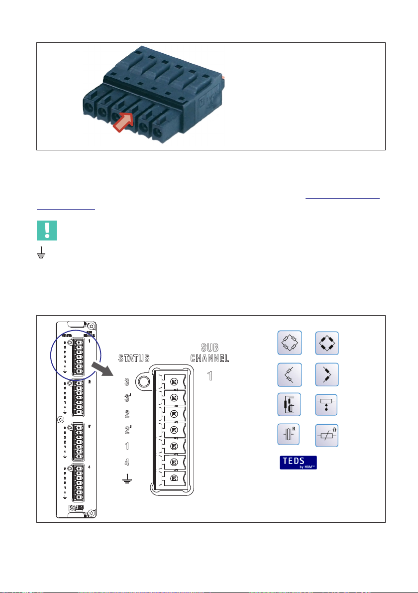
5.1.1 Connecting transducers
All PMX plug-in cards (PX401, PX455, PX460, PX878) are supplied as standard with easy-
fit push-in plug terminals. But you can also obtain screw-type terminals from Phoenix
Contact (www.phoenixcontact.com
).
The clamping area is 0.2mm2(AWG24) to 1.5mm2(AWG16). If you need to connect
multiple wires to one terminal, adapt the wire cross-sections accordingly. Use 10mm
wire end ferrules (without plastic collars) to connect the wires to the terminals wherever
possible.
Notice
The plug terminals are not interchangeable ex factory. Depending on the sensor type, plug
connection errors can damage the plug-in card.
Use the supplied coding pins to prevent interchanging.
The plug terminals can be protected by coding pins against interchanging. To do this,
insert a coding pin fully into one of the slots in the device sockets and snap it off from the
holder - see Fig. 5.1. Use a different slot for each plug terminal and transducer type. You
can also use more than one coding pin for one plug terminal.
Fig. 5.1 Coding pin 90% inserted
Remove the lug on the corresponding plug terminal connector, using a knife for example
(Fig. 5.2).
13
PMX
QUICK START
Fig. 5.2 Lug (arrow) on a plug terminal (zoomed view)
Attach the shield of the transducer cable to the ground connection provided on the PMX's
multipoint connector, in accordance with HBM Greenline information https://www.hbm.
com/Greenline.
Important
The ground terminal on the PMX is not a protective ground (connection optional).
The measurement system features automatic current limitation for each device card and
for the PMX basic device.
Connect your transducers to the measurement cards (plug terminals).
Zero-wire TEDS
PMX
QUICK START
14
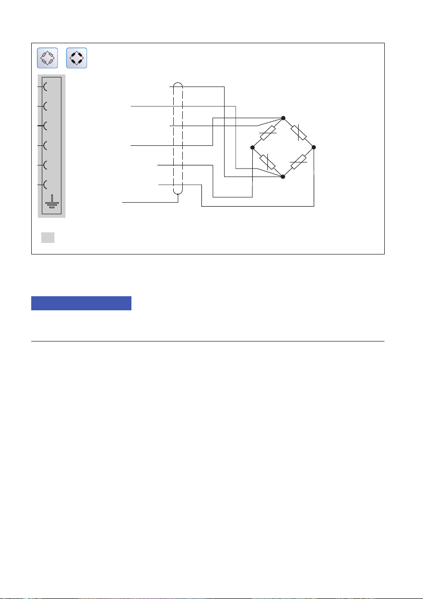
Measurement signal +
Sense lead *
Bridge excitation voltage +
Sense lead +
Bridge excitation voltage *
Cable shield
Measurement signal *3
2
14
rd
wh
gr
bk
gn
bl
1
2'
3
3'
2
4
Cable color codes for HBM transducer cables:
wh= white; bk= black; bl= blue; rd= red; gn= green; gy= gray
Transducer connection
plug terminal
Fig. 5.3 PX455 pin assignment in 6-wire circuit, based on the example of a force
transducer
Notice
The transducers can also be connected if you have previously connected the voltage
supply.
15
PMX
QUICK START
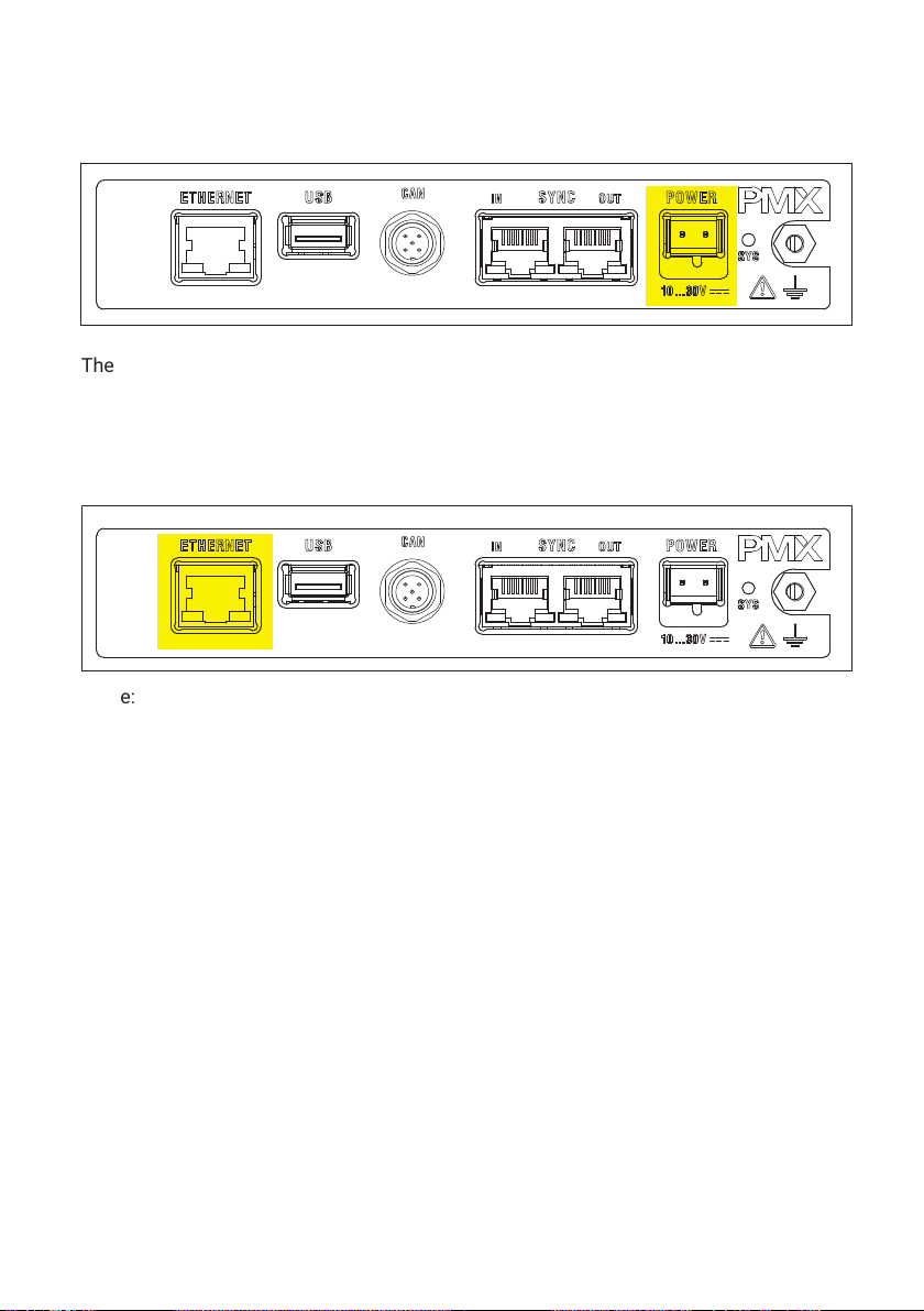
5.1.2 Connecting the power supply
The power supply must be at least 15W.
ÑÑ
ÑÑ
The PMX boots, and then displays its system status. The system LED must light up green.
This process takes a few seconds.
5.1.3 Connecting to a PC
Connect the PMX to a PC via the Ethernet socket.
ÑÑ
Cable: Standard Ethernet cable (Cat5)
The PMX is set to DHCP (automatic address assignment) at the factory. Set your PC to
DHCP as well. The IP addresses will then be set automatically. This process takes sev
eral tens of seconds.
Call the PMX web server by entering "PMX/" in the address bar of your browser.
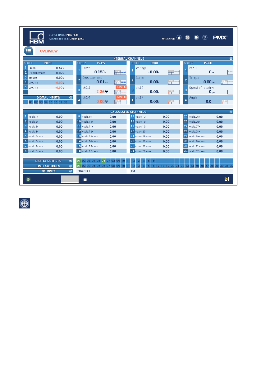
The PMX web server appears, showing the start screen (overview).
PMX
QUICK START
16
The PMX system is now ready for measurement, and you can see live measured values.
uClick on the globe icon to switch to another PMX web server language.
17
PMX
QUICK START
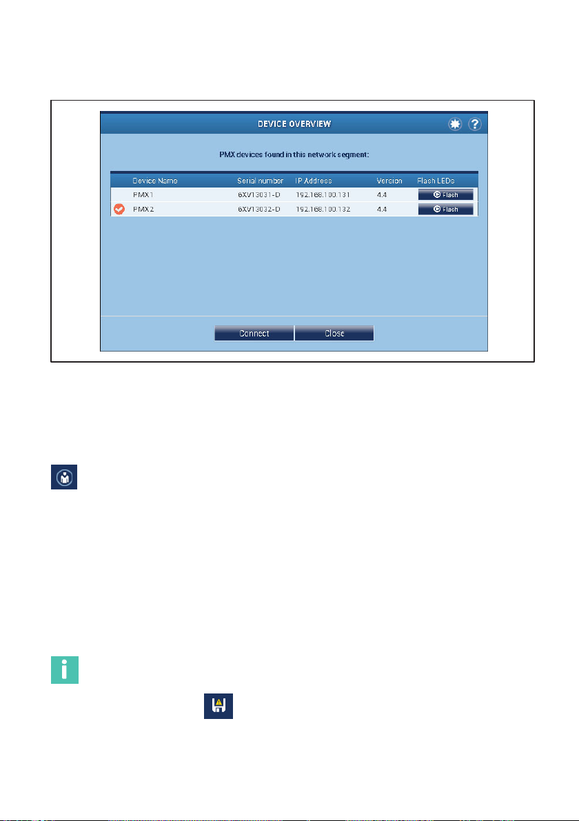
If there are multiple PMX devices in the network, this selection box will appear before the
overview:
uCheck the desired PMX.
uConfirm with Connect.
The flash function allows the device to be identified by flashing all the device LEDs.
5.1.4 Configuring the PMX
uClick on the user icon to go to the Maintenance or Administrator level. Depend
ing on authorization, you can make the following settings:
-Assign sensors
-Assign units
-Set filters
-Monitor maximum and minimum values
-Monitor limit values (Thresholds)
-Set up virtual (calculated) channels
-Configure digital and analog inputs/outputs
-Create and administer parameter sets
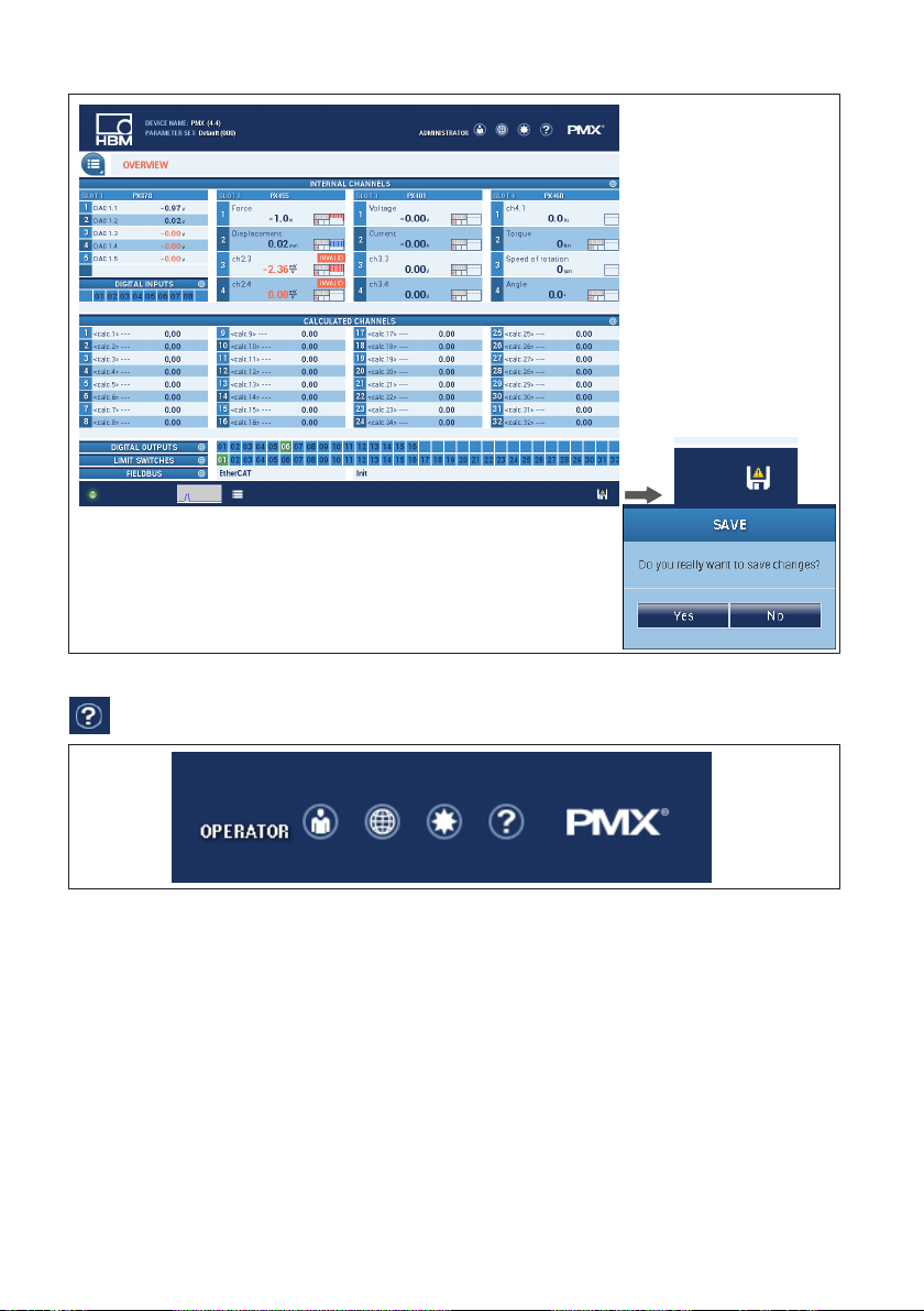
Information
Click on the floppy disk icon to save changed settings power failsafe to the device.
PMX
QUICK START
18
Confirmation prompt
uTo get additional help, click on the Help icon.
The web server help opens with information relevant to the displayed page.
5.2 Typical operating sequence (measurement example)
The easiest way to configure the PMX measuring amplifier and its measurement chan
nels is via the PMX web browser. The sensors, Ethernet cable and voltage supply must be
properly connected.
The overview shows the PMX with all its measurement cards and signals, as well as all
device information.
Other manuals for PMX
1
Table of contents
Languages:
Other HBK Industrial Equipment manuals


