HBK PW37P User manual
PW37P
ENGLISH DEUTSCH FRANÇAIS
Mounting Instructions
Montageanleitung
Notice de montage

Hottinger Brüel & Kjaer GmbH
Im Tiefen See 45
D-64293 Darmstadt
Tel. +49 6151 803-0
Fax +49 6151 803-9100
www.hbkworld.com
Mat.: 7-0201.0001-1
DVS: A04856 03 Y00 01
06.2023
EHottinger Brüel & Kjaer GmbH
Subject to modifications.
All product descriptions are for general information
only. They are not to be understood as a guarantee of
quality or durability.
Änderungen vorbehalten.
Alle Angaben beschreiben unsere Produkte in allge
meiner Form. Sie stellen keine Beschaffenheits- oder
Haltbarkeitsgarantie dar.
Sous réserve de modifications.
Les caractéristiques indiquées ne décrivent nos
produits que sous une forme générale. Elles
n'impliquent aucune garantie de qualité ou de
durabilité.

PW37P
ENGLISH DEUTSCH FRANÇAIS
Mounting Instructions

PW37P
TABLE OF CONTENTS
2
TABLE OF CONTENTS
1 Safety instructions 3................................................
2 Markings used 6....................................................
2.1 The markings used in this document 6.................................
2.2 Symbols on the load cell 6............................................
3 Conditions at the mounting location 7.................................
3.1 Protection against corrosion 7........................................
3.2 Cleaning 7.........................................................
3.3 Deposits 7.........................................................
4 Mechanical installation 8............................................
4.1 Important precautions during installation 8..............................
4.2 Mounting 8........................................................
5 Electrical connection 10..............................................
5.1 Connection in a 6-wire configuration 10..................................
5.2 Connection in a 4-wire configuration 10..................................
5.3 Shortening the cable 11...............................................
5.4 Extension cables 11..................................................
5.5 Parallel connection 11................................................
5.6 EMC protection 11...................................................
6 Dimensions 13......................................................
7 Accessories 14......................................................
8 Specifications 15....................................................

3
PW37P
SAFETY INSTRUCTIONS
1 SAFETY INSTRUCTIONS
Intended use
Load cells of the PW37…type series are designed for technical weighing applications
within the load limits detailed in the specifications. Any other use is not the intended use.
The load cells may only be installed by qualified personnel in compliance with the specifi
cations and with the safety requirements and regulations of these mounting instructions.
It is also essential to observe the applicable legal and safety regulations for the applica
tion concerned. The same applies to the use of accessories.
Load cells are not intended for use as safety components. Please also refer to the "Addi
tional safety precautions" section. Proper and safe operation of the load cells requires
proper transportation, correct storage, siting and mounting, and careful operation.
Load carrying capacity limits
Comply with the data in the technical data sheets when using the load cells. The respec
tive specified maximum loads in particular must never be exceeded. Do not exceed the
values stated in the technical data sheets, forexample
SLimit load
SLimit load at max. eccentricity
SLimit lateral loading
SBreaking loads
STemperature limits
SLimits of electrical load-carrying capacity
Note that when several load cells are installed in a scale, there is not always an even load
distribution on the individual load cells.
Use as a machine element
The load cells can be used as machine elements. When used in this manner, it must be
noted that, to favor greater sensitivity, the load cell is not designed with the safety factors
usual in mechanical engineering. Please refer to the "Load-carrying capacities" section
and to the specifications.
Accident prevention
The applicable accident prevention regulations must be taken into account, even though
the maximum capacity in the destructive range is well in excess of the full scale value.

PW37P
SAFETY INSTRUCTIONS
4
Additional safety precautions
Load cells cannot (as passive transducers) implement any (safety-relevant) cutoffs. This
requires additional components and constructive measures, for which the installer and
operator of the plant is responsible.
In cases where a breakage or malfunction of the load cells would cause injury to persons
or damage to equipment, the user must take appropriate additional safety measures that
meet at least the requirements of applicable safety and accident prevention regulations
(e.g. automatic emergency shutdown, overload protection, catch straps or chains, or
other fall protection).
The electronics conditioning the measurement signal should be designed so that mea
surement signal failure cannot subsequently cause damage.
General dangers of failing to follow the safety instructions
Load cells are state-of-the-art and reliable. There may be dangers involved if the trans
ducers are mounted, set up, installed and operated inappropriately, or by untrained per
sonnel. Everyone involved with siting, starting up, operating or repairing a load cell must
have read and understood the mounting instructions and in particular the technical safety
instructions. Load cells can be damaged or destroyed by non-designated use of the load
cells, or by non-compliance with the mounting and operating manual, these safety instruc
tions or any other applicable safety regulations (safety and accident prevention regula
tions of the Employers' Liability Insurance Association) when using the load cells. Load
cells can break, particularly in the case of overloading. The breakage of a load cell can
also cause damage to property or injury to persons in the vicinity of the load cell.
If load cells are not used according to their designated use, or if the safety instructions or
specifications in the mounting and operating manual are ignored, it is also possible that
the load cells may fail or malfunction, with the result that persons or property may be
affected (due to the loads acting on or being monitored by the load cells).
The scope of supply and performance of the transducer covers only a small area of
weighing technology, as measurements with (resistive) strain gage sensors presuppose
the use of electronic signal conditioning. In addition, equipment planners, installers and
operators should plan, implement and respond to the safety engineering considerations
of the weighing technology in such a way as to minimize residual dangers. Comply with
pertinent national and local regulations.
Conversions and modifications
The design or safety engineering of the transducer must not be modified without our ex
press permission. Any modification shall exclude all liability on our part for any damage
resulting therefrom.
Maintenance
The PW37…load cells are maintenance free.

5
PW37P
SAFETY INSTRUCTIONS
Resale
If the load cell is resold, these mounting instructions must be included with the load cell.
Environmental protection, disposal
In accordance with national and local environmental protection, material recovery and
recycling regulations, old transducers that can no longer be used must be disposed of
separately and not with normal household waste.
If you need more information about disposal, please contact your local authorities or the
dealer from whom you purchased the product.
Qualified personnel
Qualified personnel means persons entrusted with installing, mounting, starting up and
operating the product, who possess the appropriate qualifications for their function.
This includes people who meet at least one of the three following requirements:
1. Knowledge of the safety concepts of automation technology is a requirement and as
project personnel, you must be familiar with these concepts.
2. As automation plant operating personnel, you have been instructed how to handle the
machinery. You are familiar with the operation of the equipment and technologies
described in this documentation.
3. As commissioning engineers or service engineers, you have successfully completed
the training to repair the automation systems. You are also authorized to operate,
ground and mark circuits and equipment in accordance with safety engineering stan
dards.

PW37P
MARKINGS USED
6
2 MARKINGS USED
2.1 The markings used in this document
Important instructions for your safety are specifically identified. It is essential to follow
these instructions in order to prevent accidents and damage to property.
Symbol Significance
WARNING This marking warns of a potentially dangerous situ
ation in which failure to comply with safety require
ments can result in death or serious physical injury.
CAUTION This marking warns of a potentially dangerous
situation in which failure to comply with safety
requirements can result in slight or moderate physical
injury.
Notice This marking draws your attention to a situation in
which failure to comply with safety requirements can
lead to damage to property.
Important
This marking draws your attention to important in
formation about the product or about handling the
product.
Tip
This marking indicates application tips or other
information that is useful to you.
Information
This marking draws your attention to information
about the product or about handling the product.
Emphasis
See …
Italics are used to emphasize and highlight text and
identify references to sections, diagrams, or external
documents and files.
2.2 Symbols on the load cell
CE mark
The CE mark enables the manufacturer to guarantee that the product com
plies with the requirements of the relevant EC directives (the declaration of
conformity is available at http://www.hbm.com/HBMdoc
).

7
PW37P
CONDITIONS AT THE MOUNTING LOCATION
3 CONDITIONS AT THE MOUNTING LOCATION
Series PW37 load cells are hermetically encapsulated and are therefore very insensitive
to the effects of moisture and humidity. The transducers achieve protection class IP68
(test conditions: 100 hours under 1m water column) and IP69K (water at high pressure,
steam cleaning), as per DIN EN60529. Nevertheless, the load cells should be protected
against constant humidity and moisture.
3.1 Protection against corrosion
The load cells must be protected against chemicals that could attack the transducer body
steel or the cable.
Notice
Acids and all substances that release ions also attack stainless steels and their weld
seams.
The resultant corrosion can cause the transducer to fail. If this is the case, you must pro
vide appropriate means of protection.
3.2 Cleaning
The load cell has been designed according to the EHEDG design guidelines to allow for
easy, mild cleaning. When mounting the load cell, make certain it can be reached from all
sides for cleaning. Cleaning can be performed without dismounting the load cell and
should be done regularly. The surface of the load cell must not be damaged with sharp-
edged brushes during cleaning.
3.3 Deposits
Dust, dirt and other foreign matter must not be allowed to accumulate sufficiently to di
vert some of the measuring force onto the housing, thus distorting the measured value
(force shunt).
PW37P
MECHANICAL INSTALLATION
8
4 MECHANICAL INSTALLATION
4.1 Important precautions during installation
SHandle the transducer with care.
SWelding currents must not be allowed to flow through the transducer. If there is a risk
that this might happen, you must use a suitable low-ohm connection to electrically
bypass the transducer. HBM provides the highly flexible EEK ground cable for this
purpose, for example. It can be screwed on above and below the transducer.
SMake sure that the transducer cannot be overloaded.
WARNING
There is a danger of the transducer breaking if it is overloaded. This can cause danger for
the operating personnel of the system in which the transducer is installed.
Implement appropriate safety measures to avoid overloads or to protect against the re
sulting dangers.
Notice
Load cells are precision measuring elements and need to be handled carefully. Dropping or
knocking the transducer may cause permanent damage. Make sure that the transducer
cannot be overloaded, including while it is being mounted.
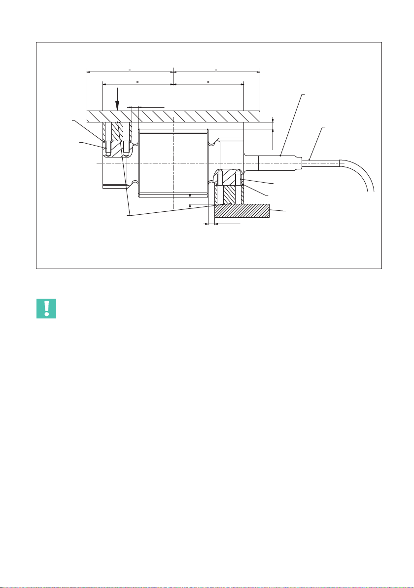
4.2 Mounting
Attach the load cells at the mounting holes and apply the load to the other end. The scope
of supply includes 2 seals for sealing the gap surfaces against microbiological contami
nation. The screws and tightening torques to be used are given in the table below:
Version Thread Max. thread
reach
Min. property
class
Tightening
torque1)
Standard M6/M8 (200 kg) 12 mm 10.9 14 N⋅m/25 N⋅m
Rustless M6/M8 (200 kg) 12 mm A2-80 or A4-80 14 N⋅m/25 N⋅m
1) Recommendedvalue for the specified property class. Please comply with the screw manufacturer's
instructions with regard to screw dimensions.
9
PW37P
MECHANICAL INSTALLATION
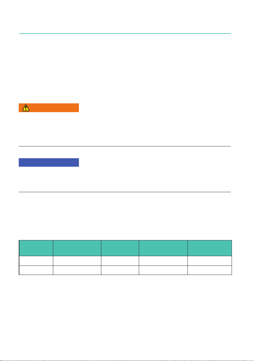
Dimensions in mm
Platform center
Load application
Run the cable
in a straight
line from the
connector
Mounting holes
Mounting base
Seal (in
scope of
supply)
Mounting
holes
Seal (in scope of supply)
Mount plug with
tightening torque of
4 Nm
min. 6 *
min. 6 *
min. 6 *
Mounting plates, connect
ing parts and screw con
nections have to be con
structed by the customer
in accordance with the
EHEDG design guidelines.
Product contact area
* According to the EHEDG design guidelines a minimum
distance of 6 mm is recommended for easy cleanability.
min. 6 *
Fig. 4.1 Load application and installation
Important
Load must not be applied to the side where the cable connection is located, as this would
cause a force shunt through the cable.
The intermediate plates should be flush against the load cell on all sides (see connection
dimensions in section 6 „Dimensions“, page 13).

PW37P
ELECTRICAL CONNECTION
10
5 ELECTRICAL CONNECTION
The following can be connected for measurement signal conditioning:
SCarrier-frequency amplifiers
SDC voltage amplifiers
designed for strain gage measurement systems.
5.1 Connection in a 6-wire configuration
Plug-in contact 1 = measurement signal (+)
Plug-in contact 6 = excitation voltage (-)
Plug-in contact 5 = sense lead (-)
Plug-in contact 7 = excitation voltage (+)
Plug-in contact 3 = sense lead (+)
Plug-in contact 8 = measurement signal (-)
2
3
4
5
6
7
1
8
Plug-in contact 2 = not in use
Plug-in contact 4 = not in use
Fig. 5.1 Connector pin assignment
With this connector pin assignment, the output voltage on the measuring amplifier is pos
itive when the transducer is loaded (see Fig. 4.1). The pin assignment for the cables avail
able as accessories can be found in section 7 on page 14.
5.2 Connection in a 4-wire configuration
When transducers in a 6-wire configuration are connected to amplifiers in a 4-wire config
uration, the sense leads of the transducers must be connected to the corresponding exci
tation voltage leads: marking (+) with (+) and marking (-) with (-), see Fig. 5.1. This mea
sure also reduces the cable resistance of the excitation voltage leads. However, there will
be a voltage loss on the supply leads due to the cable resistance that is still present and
not compensated for by the 6-wire configuration. A large part of this loss can be elimi
nated by a calibration, however, the temperature-dependent part remains.

11
PW37P
ELECTRICAL CONNECTION
Important
The TCsvalue given for the transducer in the specifications therefore does not apply for
the cable and transducer combination when connection is in a 4-wire configuration, where
the cable percentage must be added.
5.3 Shortening the cable
If the transducer is connected to an amplifier with a 6-wire configuration, the transducer
cable can be shortened as required without adversely affecting the measurement accu
racy.
5.4 Extension cables
Only use shielded, low-capacitance measurement cables for extension. Ensure that the
connection is perfect, with a low contact resistance.
The cable of a 6-wire transducer can be extended with a cable of the same type.
5.5 Parallel connection
Only load cells with an aligned output (nominal (rated) sensitivity and output resistance)
are suitable for parallel connection. This option is not available with type PW37 load cells.
5.6 EMC protection
Electrical and magnetic fields often induce interference voltages in the measuring circuit.
To ensure reliable measurement, however, the transducer must be able to transmit signal
differences of a few μV to the analysis unit without interference.
Planning the shielding design
Due to the numerous application options and differing local constraints, we can only
provide you with general information on correct connection. The shielding design suitable
for your application must be planned locally by an appropriate specialist.
HBM load cells with shielded, round cables are EMC-tested in accordance with the
EU Directive and bear the CE mark. Voltage surges as per EN 61000-4-5 can give rise to
deviations from the load cell’s specified accuracy. These surges in plants are caused by
lightning strikes or switching operations in power circuits, for example, and disappear
again when interference is no longer active. This is particularly evident with cables over
30 m long or if the equipment is used outdoors. Customers should take additional pre
cautions in these cases.
Please note:
SConnect the connecting cable shield all over the surface of the shielding electronics
housing. When using several load cells, connect the shields all over the surface of the
junction box (combination of transducer signals, e.g. type VKK2 from HBM). From

PW37P
ELECTRICAL CONNECTION
12
there, connect the measurement cable for the electronics over the surface of the
junction box and the shielding electronics housing.
SThe shield of the connecting cable must not be used for discharging potential
differences within the system. You must therefore lay sufficiently dimensioned
potential equalization lines to compensate for possible potential differences.
SUse shielded low-capacitance measurement cables only (HBM cables fulfill these
conditions).
SDo not route measurement cables parallel to electric cables, especially power lines
and control circuits. If this is not possible, protect the measurement cable, for
example with steel conduits.
SAvoid stray fields from transformers, motors and contact switches.

13
PW37P
DIMENSIONS
6 DIMENSIONS
Dimensions in mm
Connector plug
Maximum capacity 50 kg, 100 kg: M6
Maximum capacity 200 kg: M8
PW37P
ACCESSORIES
14
7 ACCESSORIES
Connection cable
Connection cable with M12 F male connector, 8-pin, stainless
steel IP68/IP69K, hygiene design, 3 m long
1-KAB175-3-1
Connection cable with M12 F male connector, 8-pin, stainless
steel IP68/IP69K, hygiene design, 6 m long
1-KAB175-6-1
Connection cable with M12 F male connector, 8-pin, stainless
steel IP68/IP69K, hygiene design, 12 m long
1-KAB175-12-1
For connection cable specifications, see separate data sheet B3643.
Pin assignment 1-KAB175
Color code Connection
White Measurement signal (+)
Red Measurement signal (-)
Blue Excitation voltage (+)
Black Excitation voltage (-)
Green Sense lead (+)
Gray Sense lead (-)
Spare part
1 set of replacement seals, consisting of 2 seals (EPDM), order no. E-9278.0014


PW37P
SPECIFICATIONS
16

PW37P
ENGLISH DEUTSCH FRANÇAIS
Montageanleitung

PW37P
INHALTSVERZEICHNIS
2
INHALTSVERZEICHNIS
1 Sicherheitshinweise 3...............................................
2 Verwendete Kennzeichnungen 6......................................
2.1 In dieser Anleitung verwendete Kennzeichnungen 6......................
2.2 Auf der Wägezelle angebrachte Symbole 6..............................
3 Bedingungen am Einbauort 7.........................................
3.1 Korrosionsschutz 7.................................................
3.2 Reinigung 7........................................................
3.3 Ablagerungen 7.....................................................
4 Mechanischer Einbau 8..............................................
4.1 Wichtige Vorkehrungen beim Einbau 8.................................
4.2 Montage 8.........................................................
5 Elektrischer Anschluss 10............................................
5.1 Anschluss in Sechsleiter‐Technik 10....................................
5.2 Anschluss in Vierleiter‐Technik 10......................................
5.3 Kabelkürzung 11.....................................................
5.4 Kabelverlängerung 11................................................
5.5 Parallelschaltung 11..................................................
5.6 EMV-Schutz 11......................................................
6 Abmessungen 13....................................................
7 Zubehör 14.........................................................
8 Technische Daten 15.................................................
Table of contents
Languages:
Other HBK Industrial Equipment manuals


