HBK RTN/M2 User manual
RTN/M2
RTN/M2LAR, RTN/M2LA, RTN/M2LBR, RTN/M2LB
ENGLISH DEUTSCH FRANÇAIS ESPAÑOL
Mounting Instructions
Montageanleitung
Notice de montage
Instrucciones de montaje

Hottinger Brüel & Kjaer GmbH
Im Tiefen See 45
D-64293 Darmstadt
Tel. +49 6151 803-0
Fax +49 6151 803-9100
www.hbkworld.com
Mat.: 7-2001.1088
DVS: A01867 02 YS0 03
05.2022
EHottinger Brüel & Kjaer GmbH
Subject to modifications.
All product descriptions are for general information
only. They are not to be understood as a guarantee of
quality or durability.
Änderungen vorbehalten.
Alle Angaben beschreiben unsere Produkte in allge
meiner Form. Sie stellen keine Beschaffenheits- oder
Haltbarkeitsgarantie dar.
Sous réserve de modifications.
Les caractéristiques indiquées ne décrivent nos
produits que sous une forme générale. Elles
n'impliquent aucune garantie de qualité ou de
durabilité.
Reservado el derecho a modificaciones.
Todos los datos describen nuestros productos de
manera general. No representan ninguna garantía de
calidad o de durabilidad.

RTN/M2
RTN/M2LAR, RTN/M2LA, RTN/M2LBR, RTN/M2LB
ENGLISH DEUTSCH FRANÇAIS ESPAÑOL
Mounting Instructions

RTN/M2
TABLE OF CONTENTS
2
TABLE OF CONTENTS
1 Safety instructions 3................................................
2 Markings used 5....................................................
2.1 The markings used in this document 5.................................
3 General 6..........................................................
4 Mounting preparation 8.............................................
5 Mounting 12........................................................
6 Dimensions 15......................................................
7 Specifications RTN/M2L... weighing modules 21.........................

3
RTN/M2
SAFETY INSTRUCTIONS
1 SAFETY INSTRUCTIONS
In cases where a breakage would cause injury to persons or damage to equipment, the
user must take appropriate safety measures (such as fall protection, overload protection,
etc.).
It is essential to comply with the relevant accident prevention regulations. In particular
you should take into account the limit loads quoted in the specifications.
Use in accordance with the regulations
The weighing modules have been designed for weighing applications. Use for any
additional purpose shall be deemed to be not in accordance with the regulations.
In the interests of safety, the weighing modules should only be operated as described in
the Mounting Instructions. It is also essential to observe the appropriate legal and safety
regulations for the application concerned during use. The same applies to the use of
accessories.
The weighing modules are not safety elements within the meaning of its use as intended.
Proper and safe operation of this weighing module requires proper transportation,
correct storage, assembly and mounting and careful operation and maintenance.
General dangers due to non‐observance of the safety instructions
The weighing modules correspond to the state of the art and are fail‐safe. The weighing
modules can give rise to residual dangers if they are inappropriately installed and
operated by untrained personnel.
Everyone involved with the installation, commissioning, maintenance or repair of a
weighing module must have read and understood the Mounting Instructions and in
particular the technical safety instructions.
Residual dangers
The scope of supply and performance of the weighing modules covers only a small area
of weighing technology. In addition, equipment planners, installers and operators should
plan, implement and respond to the safety engineering considerations of weighing
technology in such a way as to minimise residual dangers. Prevailing regulations must be
complied with at all times. There must be reference to the residual dangers connected
with weighing technology.
Environmental conditions
In the context of your application, please note that all materials which release chlorine
ions will attack all grades of stainless steel and their welding seams. In such cases the
operator must take appropriate safety measures.

RTN/M2
SAFETY INSTRUCTIONS
4
With environmental conditions that cannot be clearly defined, HBK recommends to
provide the load cells and weighing modules with a protective coating which matches
these conditions (after mounting) in order to prevent the influence of aggressive media.
Please take into account the resistance of the cable material and the mounting parts.
Prohibition of own conversions and modifications
The weighing modules must not be modified from the design or safety engineering point
of view except with our express agreement. Any modification shall exclude all liability on
our part for any damage resulting therefrom.
Qualified personnel
These weighing modules are only to be installed by qualified personnel strictly in
accordance with the specifications and with the safety rules and regulations which
follow. It is also essential to observe the appropriate legal and safety regulations for the
application concerned. The same applies to the use of accessories.
Qualified personnel means persons entrusted with the installation, fitting, commissioning
and operation of the product who possess the appropriate qualifications for their
function.
Accident prevention
Although the specified brealing load is several times the full scale value, the relevant
accident prevention regulations from the trade associations must be taken into
consideration.

5
RTN/M2
MARKINGS USED
2 MARKINGS USED
2.1 The markings used in this document
Important instructions for your safety are specifically identified. It is essential to follow
these instructions in order to prevent accidents and damage to property.
Symbol Significance
CAUTION This marking warns of a potentially dangerous
situation in which failure to comply with safety
requirements can result in slight or moderate physical
injury.
Notice This marking draws your attention to a situation in
which failure to comply with safety requirements can
lead to damage to property.
Important This marking draws your attention to important in
formation about the product or about handling the
product.
Tip This marking indicates application tips or other
information that is useful to you.
Information This marking draws your attention to information
about the product or about handling the product.
Emphasis
See …
Italics are used to emphasize and highlight text and
identify references to sections, diagrams, or external
documents and files.

RTN/M2
GENERAL
6
3 GENERAL
HBK offers the RTN/M2(L)... weighing module for RTN load cells with max. capacities of
1 t ... 33 t. The ”L” in the type designation signifies that the module has been fitted with a
stay rod. “A” signifies rubber‐metal bearing, “B” stands for pendulum bearing.
Product types RTN/M2LA...
Order number Max. capacity
for load cell
Material Version
1-RTN/M2LAR2.2T 1 t ... 2.2 t stainless steel WITH stay rod
1-RTN/M2AR2.2T WITHOUT stay rod
1-RTN/M2LAR4.7T 4.7 t stainless steel WITH stay rod
1-RTN/M2AR4.7T WITHOUT stay rod
1-RTN/M2LAR22T 10 t ... 22 t stainless steel WITH stay rod
1-RTN/M2AR22T WITHOUT stay rod
1-RTN/M2LA33T 33 t galvanized WITH stay rod
1-RTN/M2A33T WITHOUT stay rod
Product types RTN/M2LB...
Order number Max. capacity
for load cell
Material Version
1-RTN/M2LBR4.7T/2 1 t ... 4.7 t stainless steel WITH stay rod
1-RTN/M2BR4.7T/2 WITHOUT stay rod
1-RTN/M2LBR22T 10 t ... 22 t stainless steel WITH stay rod
1-RTN/M2BR22T WITHOUT stay rod
1-RTN/M2LB33T 33 t galvanized WITH stay rod
1-RTN/M2B33T WITHOUT stay rod

7
RTN/M2
GENERAL
The weighing modules have been primarily designed for use in tank weighing. As a rule,
the weighing modules are equipped with adjustable limit stops that limit horizontal move
ments, for example by wind forces or in mixer operation. In addition, the modules are
provided with a anti‐liftoff device which prevents the tank from lifting off. However, en
sure that the specified data (see chapter 7 on page 21) are not exceeded.
The modules comprise a lower module plate for mounting on the basic construction
(foundations), a load cell dummy with load introduction elements and the upper module
plate for tank mounting. For load introduction into the load cell, a rubber‐metal bearing
(with RTN/M2LA) or a pendulum bearing (with RTN/M2LB)is used which allows for
horizontal shifting of the load applied. The weighing modules are completely fitted with a
load cell dummy that can be loaded, with a ground cable, and a securing device for
transport.

RTN/M2
MOUNTING PREPARATION
8
4 MOUNTING PREPARATION
CAUTION
The weighing modules are delivered completely assembled, however, without a load cell.
Instead of the load cell, a dummy has been assembled into the weighing module, which is
capable of taking up the specified loads. Before the weighing module is mounted under
neath the tank, vessel or silo, check whether dummy replacement through the load cell will
still be possible even if the tank is placed on the weighing module. In order to effect the
replacement, a suitable lifting device is necessary that is capable of lifting the tank by at
least 10 mm. Pipe connections mounted on the tank or the feed‐in or discharge systems
have to be vertically movable or separable.
Notice
If this is not the case, the dummy must be replaced by an appropriate RTN load cell already
before the weighing module is mounted.
General mounting preparations
SEnsure that the assembly/siting areas provided are clean, level and horizontally
aligned. Any askew positions can be compensated for, depending on the assembly
situation, for example by appropriate wedges and compensation plates (weld in posi
tion) or by grinding down the assembly area. However, module plates must not be
ground down under any circumstances.
SThe foundations / basic construction and the connection of the superstructure must
be sufficiently rigid in order to avoid deformations (e.g. deflections) under load.
SIn order to provide for fitting and assembly free from any constraining forces, the
mounting bores on the basic construction and the tank connection must be suffi
ciently aligned.
SAn even loading on the bearing points is to be sought. To this end, in particular for
statically indefinite bearings, ensure that the height level setting at the bearing points
is correct (provide spacer plates, 5 x 1 mm included in scope of delivery).
SUndo transport protection device and stops, fit height adjustment plates (dependent
on maximum capacity, see Dimensions).

9
RTN/M2
MOUNTING PREPARATION
Notice
How to use the enclosed grease tube
Before fitting the load cell, the enclosed grease must be applied to the upper thrust piece
and to the underside of the pendulum bearing (with RTN...B) in order to minimize friction
between the inside surface of the thrust piece and the load introduction element of the
RTN load cell or pendulum bearing.
Use of the spacer plates provided
The scope of delivery of the module includes 2 x 5 spacer plates. They are used for the
vertical adjustment of the module. Five plates max. are to be fitted underneath the upper
module plate, and five plates max. between the base and the cross bracket of the
anti‐liftoff device
Important
Ensure that all screws are fitted with U‐washers.
RTN/M2
MOUNTING PREPARATION
10
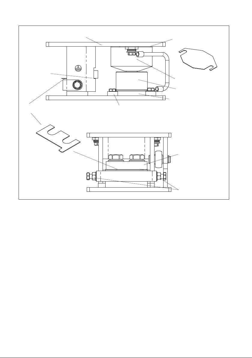
5 plates max. for
height adjustment
5 plates max. for height adjustment
Upper module plate
Centering disc
(only up to 4.7 t
max. capacity)
Lateral stops
Cross‐bracket
(Anti‐liftoff device)
Air gap: 1 mm
Mounting base
(only up to 4.7 t
max. capacity)
Bearing
Dummy
Fig. 4.1 Fitting of the spacer plates with 4.7 t version

11
RTN/M2
MOUNTING PREPARATION
5 plates max. for
height adjustment
5 plates max. for height adjustment
Upper module plate
Lateral stops
Cross‐bracket
(Anti‐liftoff device)
Air gap: 1 mm
Bearing
Dummy
Fig. 4.2 Fitting of the spacer plates with 10 t ... 33 t version

RTN/M2
MOUNTING
12
5 MOUNTING
SWhen fitting the tank, vessel or silo, ensure that e.g. when lowering it onto the bearing
points no shock loads act upon the module. Even short term loads that exceed the
load cell limit values can result in damage to the load cell.
SFor heavy containers or unfavourable fitting conditions, the use of appropriate fitting
aids (auxiliary supports, lifting devices) is required.
SLower module plate and upper module plate are to be firmly connected with the
foundations or tank connection.
SThe weighing modules must be assembled such that, in their original state, they are
free from lateral forces. The pendulum bearing version requires the fitted pendulum
bearing to be aligned exactly vertically, if possible. This is the case, if foundations and
tank connection are horizontal and the mounting bores on the basic construction and
the container connection are sufficiently aligned. Slotted holes in the module plates
facilitate alignment.
SFor protection against welding currents which may destroy the electronic components
of the transducer the fitted EEK4 ground cable is provided.
SEspecially in the case of a statically indefinite bearing uneven loading of the modules
can occur due to an insufficiently precise height adjustment. This unevenness is to be
checked on the individual load cells by applying an excitation voltage and comparing
the output voltages. In order to avoid any overloads, major unevenness is to be
compensated by inserting spacer plates on the bearings with the lowest loads.
Mounting of the load cell
In order to assemble the load cell into the weighing module the pre‐fitted dummy needs
to be removed.
Mounting of load cells up to a max. capacity of 4.7 t: see Fig. 4.1
SRemove the anti‐liftoff device by undoing the 2 hexagonal screws
SLoosen the lateral stops
SUse a suitable lifting device to lift the respective tank base by approx. 10 mm
SUndo the centering discs
SRemove the dummy with the mounting base of the RTN by lifting lightly and withdraw
ing to one side (for pendulum bearing version, with pendulum bearing)
SRemove mounting from dummy and fit to load cell; tightening torque of the 4 screws:
4 N⋅m
SSecure and position load cell with mounting base by means of centering discs on the
lower module plate. Apply the enclosed grease to the load introduction parts of the
load cell.

13
RTN/M2
MOUNTING
SWith the pendulum bearing version, position the pendulum bearing on the load cell.
Also apply grease.
SSlowly lower the tank while making sure that the load buttons engage with the corre
sponding seats without suffering damage.
SVertical module alignment by inserting or removing the five 1‐mm‐thick spacer plates
underneath the upper module plate.
SMount and adjust the anti‐liftoff device by inserting plates underneath such that an air
gap of about 1 mm results (see Fig. 4.1) with the tank empty.
SFirst adjust and then lock the horizontal stops. The U‐shaped bracket accounts for the
stiffness of the stops and has to be fastened with the stop screws. Please refer to the
Specifications in chapter 7 for the maximum permissible horizontal shifts (distance
from the stops). The stay rods already have been adjusted at the factory to ensure
that the load introduction parts are aligned with the load cell in the rod direction.
Should a readjustment prove necessary, the rod end bearings subsequently have to be
carefully locked.
Mounting of load cells with a max. capacity of 10 t, 15 t, 22 t and 33 t: see Fig. 4.2
SRemove the anti‐liftoff device by undoing the 2 hexagonal screws
SUse a suitable lifting device to lift the respective tank base by approx. 10 mm
SRemove the load cell dummy without the mounting base with thrust piece by lifting
lightly and withdrawing to one side (for pendulum bearing version, with pendulum
bearing)
SInsert the load cell with the thrust piece and, if necessary, the pendulum support, apply
the enclosed grease to the load introduction parts.
SSlowly lower the tank. The thrust piece above the load cell must center in the center
ing flange of the upper module plate without suffering damage.
SVertically align the module by inserting or removing the five 1‐mm‐thick spacer plates
above the thrust piece of the load cell (see Fig. 4.2)
SMount and adjust the anti‐liftoff device by inserting spacer plates underneath such
that an air gap of about 1 mm results with the tank empty.
SFirst adjust and then lock the horizontal stops. The U‐shaped bracket accounts for the
stiffness of the stops and has to be fastened with the stop screws. Please refer to the
Specifications in Chapter 7 for the maximum permissible horizontal shifts (distance
from the stops). The stay rods already have been adjusted at the factory to ensure
that the load introduction parts are aligned with the load cell in the rod direction.
Should a readjustment prove necessary, the rod end bearings subsequently have to be
carefully locked.

RTN/M2
MOUNTING
14
Notes for adjustment of the horizontal stops
Horizontal movability is ensured by the rubber‐metal or pendulum bearing. The horizontal
stops should be adjusted in compliance with the maximum permissible horizontal shift
(see chapter 7 on page 21).
Notice
Precautions during operation:
SDeposits such as dirt or corrosion particles from the tank can falsify measurement
results.
SThe limits for movability and loading capacity specified in the Specifications must not
be exceeded.
SHorizontal shifts that exceed the maximum permissible value and do not act in the
direction of the stay rod are to be avoided by aligning the other modules appropriately,
or to be taken up by other stops or devices.
SThe movement tolerance of the stay rod should be checked regularly and readjusted,
if necessary.
15
RTN/M2
DIMENSIONS
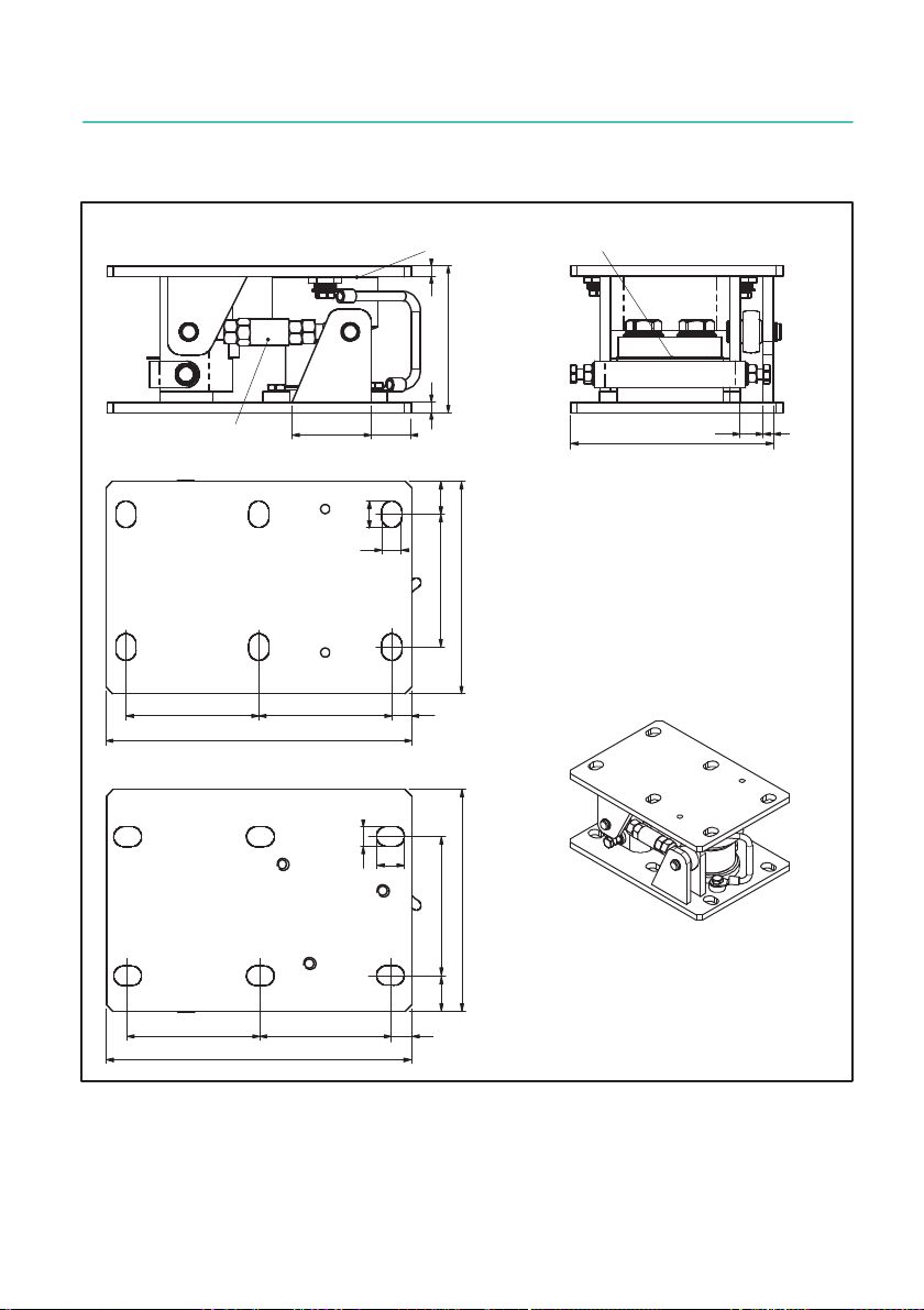
6 DIMENSIONS
RTN/M2LA - Version with rubber‐metal bearing
60
8
111
8
30 8
153 17
only version with
stay rod
max. 5 spacer plates
(110 - 115 by
spacer plates)
230
100
100100
160
25
15
View from above
20
15
View from below
230
100
100100
160
25
15
15
20
Max. capacity 1 t ... 4,7 t
Perspective view
Dimensions in mm
(1mm = 0.03937 inches)

RTN/M2
DIMENSIONS
16
RTN/M2LA - Version with rubber‐metal bearing
1022
65
148
10
10 151
255
max. 5 spacer plates
only version with stay rod
(150 - 155 by
spacer plates)
Max. capacity 10 t ... 22 t
Perspective view
310
140130
140
18
200
View from above
20
25
View from below
310
140130
140
200
25
20
18
20
20 Dimensions in mm
(1mm = 0.03937 inches)

17
RTN/M2
DIMENSIONS
RTN/M2LA - Version with rubber‐metal bearing
View from above
View from below
Max. capacity 33 t
Perspective view
85
188
12 12
193
290
max. 5 spacer plates
only version with stay rod
1226
(192 - 197 by
spacer plates)
420
200155
200
280
35
420
200155
200
280
35
22
26
26
22
35
35 Dimensions in mm
(1mm = 0.03937 inches)
RTN/M2
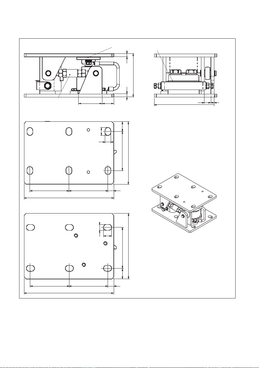
DIMENSIONS
18
RTN/M2LB - Version with pendulum bearing
max. 5 spacer plates
only version with
stay rod
8
153 17
230
100
100100
160
25
15
View from above
20
15
View from below
230
100
100100
160
25
15
15
20
Max. capacity 1 t ... 4.7 t
Perspective view
60
111
30
(110 - 115 by
spacer plates)
88
Dimensions in mm
(1mm = 0.03937 inches)
This manual suits for next models
4
Table of contents
Languages:
Other HBK Industrial Equipment manuals


