HBK FIT-AED-Kit User manual

FIT®-AED-Kit
ENGLISH DEUTSCH
Operating Manual
Bedienungsanleitung

Hottinger Brüel & Kjaer GmbH
Im Tiefen See 45
D-64293 Darmstadt
Tel. +49 6151 803-0
Fax +49 6151 803-9100
www.hbkworld.com
Mat.: 7-0101.0078
DVS: A02022 02 X00 00
12.2021
EHottinger Brüel & Kjaer GmbH
Subject to modifications.
All product descriptions are for general information
only. They are not to be understood as a guarantee of
quality or durability.
Änderungen vorbehalten.
Alle Angaben beschreiben unsere Produkte in allge
meiner Form. Sie stellen keine Beschaffenheits- oder
Haltbarkeitsgarantie dar.
FIT®-AED-Kit
ENGLISH DEUTSCH
Operating Manual

FIT®-AED-Kit
TABLE OF CONTENTS
2
TABLE OF CONTENTS
1 Safety Instructions 3................................................
2 Markings Used 5...................................................
3 Overview 6.........................................................
4 Scope of Supply 7..................................................
5 Device Default Settings 8............................................
5.1 AED9401A or AED9501A 8...........................................
5.2 AD103C in AED 8...................................................
5.3 FIT 8..............................................................
6 Setup for Initial Commissioning 9.....................................
6.1 AED9401A 10.......................................................
6.2 AED9501A 12.......................................................
6.3 FIT load cell 14......................................................
7 Initial Commissioning 16.............................................
8 Technical Support 19.................................................
9 Maintenance 20.....................................................
10 Disposal and Environmental Protection 21..............................

3
FIT®-AED-Kit
SAFETY INSTRUCTIONS
1 SAFETY INSTRUCTIONS
Intended use
The starter kit must only be used for initial setup of FIT®load cells or the
AED9401A/AED9501A. Use for any purpose other than the above is deemed improper
use.
Any person entrusted with starting up or operating the Kit must have read and
understood the operating manual, and in particular the safety instructions.
In the interests of safety, the device should only be operated by qualified personnel and
as described in the Operating Manual. The same applies to the use of accessories.
The device is not intended for use as a safety component. Proper and safe operation
requires proper transportation, correct storage, siting and mounting, and careful
operation.
Operating conditions
SProtect the Starter Kit from direct contact with water.
SProtect the Starter Kit against moisture and humidity, as well as weather conditions
such as rain or snow.
SProtect the Starter Kit from direct sunlight.
SThe Starter Kit must not be modified in its design or safety features without our
express consent. In particular, any repair or soldering work on motherboards
(replacement of components) is prohibited. When exchanging complete modules,
use only genuine parts from HBM.
SThe Starter Kit is supplied ex works with a fixed hardware and software
configuration. This must not be modified.
SThe Starter Kit is maintenance-free.
SPlease note the following when cleaning the housing:
-Disconnect the device from all current and voltage supplies.
-Never use solvents, as they may corrode the label.
-When cleaning, ensure that no liquid gets into the connections.
SStarter Kits that are no longer usable must be disposed of separately from regular
household waste in accordance with national and local regulations for
environmental protection and raw material recovery; see also section 10 on page
21.
Qualified personnel
Qualified persons are individuals entrusted with the installation, fitting, startup and
operation of the product and with the relevant qualifications for their work.
This includes people who meet at least one of the three following criteria:

FIT®-AED-Kit
SAFETY INSTRUCTIONS
4
SThey have knowledge of the safety equipment and procedures of measurement and
automation systems, and are familiar with them as project personnel.
SThey are operating personnel of measurement or automation systems and have
been instructed on how to handle the machinery. They are familiar with the opera
tion of the equipment and technologies described in this document.
SAs a commissioning or service engineer, they have successfully completed training
on the repair of automation plants. Moreover, they are authorized to start up,
ground and label circuits and equipment in accordance with safety engineering
standards.
Working safely
SThe Starter Kit must not be directly connected to the power supply system. The
supply voltage must not exceed 30VDC.
SError messages should only be acknowledged once the cause of the error has been
eradicated and there is no further danger.
SFollowing work on settings or password-protected activities, make sure that any
controls that may be connected remain in a safe condition until the switching
behavior has been tested.
General dangers of failing to follow the safety instructions
The Starter Kit corresponds to the state of the art and is failsafe. It may pose residual
dangers if deployed or operated improperly.
5
FIT®-AED-Kit
MARKINGS USED
2 MARKINGS USED
Important instructions for your safety are highlighted. Following these instructions is
essential in order to prevent accidents and damage to property.
Icon Meaning
Notice This marking draws your attention to a situation in
which failure to comply with safety requirements
could lead to property damage.
Important This marking draws your attention to important
information about the product or about handling the
product.
Information This marking draws your attention to information
about the product or about handling the product.
Emphasis
See …
Italics are used to emphasize and highlight text and
identify references to sections of the manual,
diagrams, or external documents and files.
Device -> New Bold text indicates menu items, as well as dialog
and window headings in the program environment.
Arrows between menu items indicate the sequence
in which the menus and sub-menus are called up
Sample rate Bold text in italics indicates inputs and input fields in
the user interfaces.
uThis marking indicates an action step.

FIT®-AED-Kit
OVERVIEW
6
3 OVERVIEW
The Starter Kit is used to connect the AED9401A or AED9501A, both with AD103C, or
the FIT®load cells to a PC via CANopen or DeviceNet. The Starter-KIT makes the
electrical connection to the PC, and allows you to test the function of inputs and
outputs.
Important
Use the Starter Kit only in the laboratory for initial commissioning. It must not be used
in industrial environments.
Starter Kit functions
SDirect connection of the PEAK-USB adapter for CANopen/DeviceNet.
SBus terminating resistor (120Ω) for the CAN bus.
SConnection of the diagnostics bus (RS-485 2-wire) to a PC COM port (RS-232).
The Starter Kit includes a RS-485 to RS-232 level converter for the purpose.
SBus terminating resistor (2 x 2kΩ) for the diagnostics bus.
S2 buttons for the control inputs IN1/IN2 of the AED/FIT.
S4 LEDs for the control outputs OUT1 …4 of the AED/FIT.
SConnection for the included power supply unit (24V).
SLED for the 24V power supply.
Notice
Electronic components are sensitive to electrostatic discharge (ESD). So discharge
static from yourself before working with the Starter Kit. We recommend wearing an
antistatic strap (conductive wrist strap) and using a conductive pad.

7
FIT®-AED-Kit
SCOPE OF SUPPLY
4 SCOPE OF SUPPLY
SStarter Kit PCB
SPower supply (input 100 …240VAC, output 24VDC, max. 1.25A)
SPEAK-USB adapter (CAN bus to USB)
SConnection cable (D-sub-HD15 female and male, 9-pin)
SThis operating manual
You can use the connection cable (D-sub-HD15 9-pin) either to connect the diagnos
tics bus to the PC COM port or as an extension connecting between the PEAK-USB
adapter and the Starter Kit.
Information
Download the operating manual and further information on AED and FIT from HBM's
website: AED Digital transducer electronics or FIT7A Digital load cell.

FIT®-AED-Kit
DEVICE DEFAULT SETTINGS
8
5 DEVICE DEFAULT SETTINGS
The settings described below are defaults that you will need for initial commissioning.
5.1 AED9401A or AED9501A
Settings in the AED9401A basic device (see Fig. 6.1 on page 11):
uSelect bus CANopen or DeviceNet: Switch S2
uBus terminator to on: Switch S1
uBus isolator to off: Switch S3
Settings in the AED9501A basic device (see Fig. 6.2 on page 13):
uSelect bus CANopen or DeviceNet: Switch S2
uBus terminator to on: Switch S1
5.2 AD103C in AED
Settings in the AD103C (factory settings):
SCAN bus address: 63; DeviceNet address: 63
SCAN baud rate: 125000
SDiagnostics bus address: 31
SDiagnostics bus baud rate: 38400
5.3 FIT
Settings in the FIT (factory settings):
SCAN bus address: 63; DeviceNet address: 63
SCAN baud rate: 125000
SDiagnostics bus address: 31
SDiagnostics bus baud rate: 38400

9
FIT®-AED-Kit
SETUP FOR INITIAL COMMISSIONING
6 SETUP FOR INITIAL COMMISSIONING
The pin assignment of the AEDs is shown in Fig. 6.1 on page 11 and in Fig. 6.2 on page
13. That of the FIT is shown in Fig. 6.3 on page 15. For more information, refer to the
AED and FIT operating manuals. To put the devices into operation, you must connect
them to the Starter Kit. If you do not need individual functions, such as a digital output
or the diagnostics bus, leave those connections out (no connection between Starter Kit
and device).
On the Starter Kit, the terminals of ST4 correspond directly to the adjacent terminals
KL3 and KL4, and the terminals of ST5 correspond to the adjacent terminals KL5 and
KL6, each in the same order from top to bottom. If you have an adapter compatible
with the ST4 or ST5 plugs, such as jumper cables with wire jumper sockets, you can
also use those to connect.
The complete setup comprises the following components:
SPower supply unit
SPC with USB; the PanelX program has been installed; if a COM port (RS-232) is
available, you can connect the diagnostics bus there
SPEAK-USB adapter for CAN bus
SAED9401A or AED9501A with AD103C and connected transducer or FIT load cell
SStarter Kit
SD-sub-HD15 connection cable for connecting the diagnostics bus Use a USB-to-
RS232 adapter to connect the diagnostics bus to a USB port.
The power for the AED or FIT is supplied by the Starter Kit's power supply unit.
Alternatively, you can use a different voltage source. If you do so, observe the mini
mum required voltage for the connected device (AED or FIT). The PEAK-USB converter
is powered via the USB port on the PC.
The CAN bus connections are duplicated on both the Starter Kit and the AEDs.
The in/out distinction is irrelevant, though you could connect more devices via it.
If you do so, observe the correct termination of the bus (at the ends only).
Information
The pushbuttons are not debounced, so multiple switching operations may occur when
they are pressed.
FIT®-AED-Kit
SETUP FOR INITIAL COMMISSIONING
10
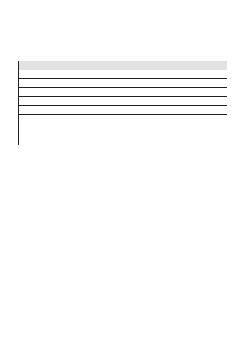
6.1 AED9401A
You can omit connections you do not need, depending on whether you want to connect
to the AED via the CAN bus or the diagnostics bus. Connect only the connections you
want on the Starter Kit to those on the AED according to the following schematic:
Connection labeling on the Starter Kit Connection labeling on the AED
UB(KL3, KL5 or KL7) UV(KL1 or KL2)
GND (KL3, KL5 or KL7) GND (KL1 or KL2)
IN1 … 2 (KL6 or KL8) IN1 … 2; also interconnect the two GND
connections of KL1 above
OUT1 … 4 (KL6 or KL8) OUT1 … 4 (KL2)
CanH in (KL4) CAN H (KL3 or KL6)
CanL in (KL4) CAN L (KL3 or KL6)
RA/TA (KL4) RA/TA (KL5)
RB/TB (KL4) RB/TB (KL5)
You can switch the inputs to high level by operating the relevant switches IN1 and IN2.
The LEDs OUT1 to OUT4 indicate the level of the corresponding outputs.
11
FIT®-AED-Kit
SETUP FOR INITIAL COMMISSIONING
PC
Power supply
unit
24VDC
Cable
(SUB-D9)
COM1
USB PEAK
adapter
KL2 KL1
KL5
KL3
KL6
off
on
on
off
Bus
terminator
Bus
isolator
Bus selection
CAN
DeviceNet S2
S3
S1
AED9401A
with AD103C
3 bl
3' gn
4 rd
1 wh
2' gr
2 bk
IN2
IN1
GND
UV
GNDOUT4
OUT3
OUT2
OUT1
RB/TB
RA/TA
CAN L
CAN H
RB/TB
RA/TA
GND
IN2
IN1
OUT4
OUT3
OUT2
OUT1
GND
UB
RB/TB
RA/TA
CanL in
CanL out
CanH in
CanH out
GND
UB
KL4
IN1
IN2
OUT4
OUT3
OUT2
OUT1
GND
Trigger
KL6 KL8
ST5
ST4
RED
RED
ST3
ST2
ST1
KL2
Starter Kit
1-FIT-AED-KIT
CAN RS232 (diag)
KL5 KL7
KL3
GND
+24V
KL1
Fig. 6.1 Connecting the AED9401A to the Starter Kit (schematic)
FIT®-AED-Kit
SETUP FOR INITIAL COMMISSIONING
12
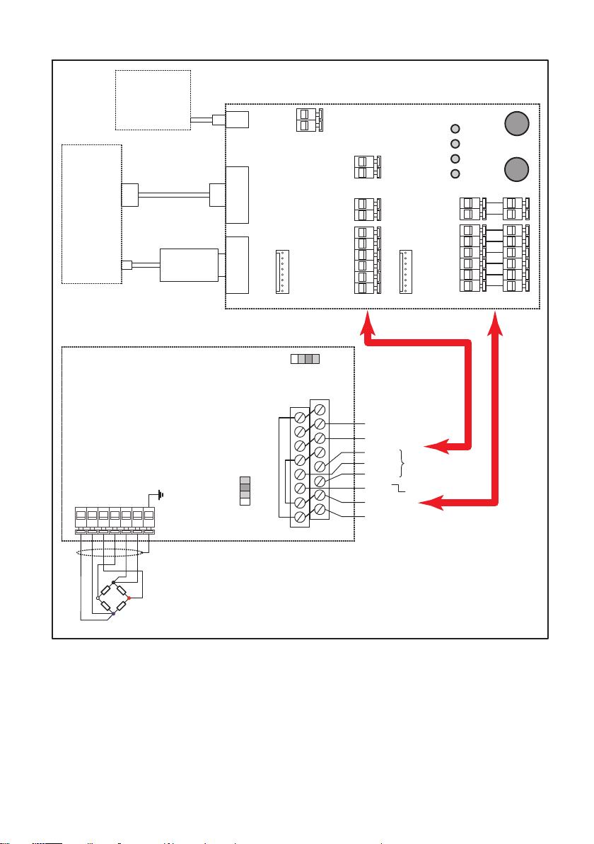
6.2 AED9501A
You can omit connections you do not need, depending on whether you want to connect
to the AED via the CAN bus or the diagnostics bus. Connect only the connections you
want on the Starter Kit to those on the AED according to the following schematic:
Connection labeling on the Starter Kit Connection labeling on the AED
UB(KL3, KL5 or KL7) +10 … 30V (KL4, pin 1, 2, 15 or 16)
GND (KL3, KL5 or KL7) GND (KL4, pin 7, 8, 13 or 14)
IN 1 (KL6 or KL8) or Trigger (KL2) IN 1 (KL4, pin 12)
CanH in (KL4) CAN H (KL4, pin 5 or 6)
CanL in (KL4) CAN L (KL4, pin 3 or 4)
RA/TA (KL4) RA/TA (KL4, pin 9)
RB/TB (KL4) RB/TB (KL4, pin 10); also connect pin 11
of KL1 to one of the other GND connec
tions
You can switch the input IN1 to high level by operating switch IN1. Note that triggering
is initiated by the falling edge (releasing the switch).
13
FIT®-AED-Kit
SETUP FOR INITIAL COMMISSIONING
2
16
1
15
KL4
CAN Low
CAN High
Bus terminator
Bus selection
CANopen
DeviceNet
off on
S1
S2
GND
IN1
+10 …30 V
GND
3 bl
3' gn
4 rd
1 wh
2' gr
2 bk
T/RA
T/RB RS-485
PC
Power supply
unit
24VDC
Cable
(SUB-D9)
COM1
USB PEAK
adapter
IN2
IN1
OUT4
OUT3
OUT2
OUT1
GND
UB
RB/TB
RA/TA
CanL in
CanL out
CanH in
CanH out
GND
UB
KL4
IN1
IN2
OUT4
OUT3
OUT2
OUT1
GND
Trigger
KL6 KL8
ST5
ST4
REDRED
ST3
ST2
ST1
KL2
Starter Kit
1-FIT-AED-KIT
CAN RS232 (diag)
KL5 KL7
KL3
GND
+24V
KL1
AED9501A
with AD103C
Fig. 6.2 Connecting the AED9501A to the Starter Kit (schematic)
FIT®-AED-Kit
SETUP FOR INITIAL COMMISSIONING
14
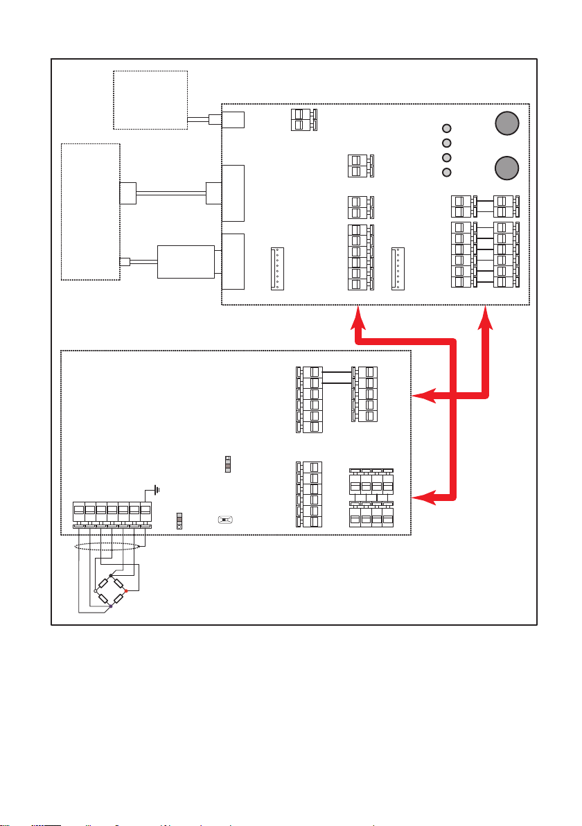
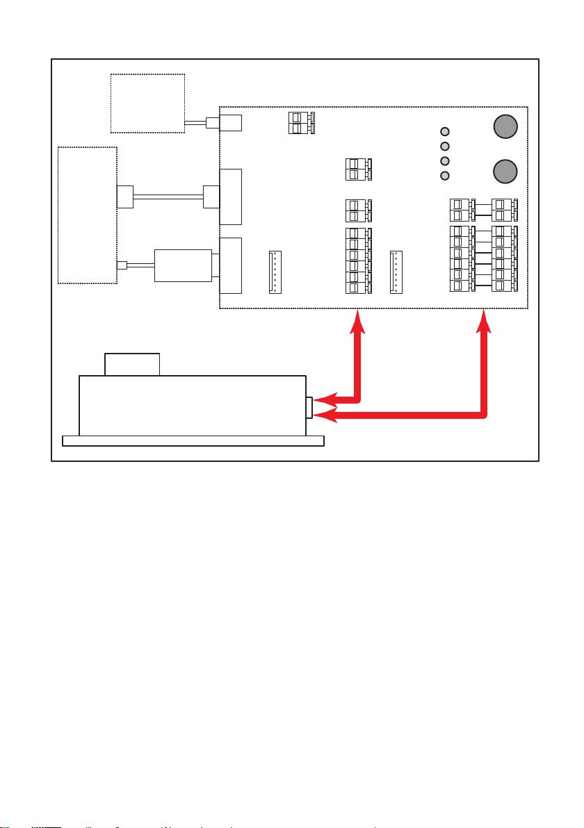
6.3 FIT load cell
You can omit connections you do not need, depending on whether you want to connect
to the FIT via the CAN bus or the diagnostics bus. Connect only the connections you
want on the Starter Kit to those of device socket 1 on the FIT. Depending on the FIT
design, the connections are used either for an RS-485 interface or for CANopen or
DeviceNet. The pins 3 and 5 indicated in the following diagram are therefore assigned
differently in the RS-485 version, and must not be connected. You can only use the
diagnostics bus here. Note that the diagnostics bus is not included in the standard
version of the FIT.
Connection labeling on the Starter Kit Connection labeling on the FIT
UB(KL3, KL5 or KL7) UB1 (pin 8)
GND (KL3, KL5 or KL7) GND (pin 1)
CanH in (KL4) CAN High IN (pin 3)
CanL in (KL4) CAN Low IN (pin 5)
RA/TA (KL4) Diag RaTa (pin 4)
RB/TB (KL4) Diag RbTb (pin 2); also connect pin 11 of
KL1 to one of the other GND connections
If you have the advanced version of the FIT, two additional connections are available
on the device socket. Connect them to the Starter Kit as needed according to the fol
lowing schematic:
Connection labeling on the Starter Kit Connection labeling on the FIT
IN1 (KL6 or KL8) IN1 (pin 4)
IN2 (KL6 or KL8) IN2 (pin 2)
OUT1 (KL6 or KL8) OUT1 (pin 7)
OUT2 (KL6 or KL8) OUT2 (pin 3)
OUT3 (KL6 or KL8) OUT3 (pin 6)
OUT4 (KL6 or KL8) OUT4 (pin 5)
You can switch the inputs to high level by operating the relevant switches IN1 and IN2.
The LEDs OUT1 to OUT4 indicate the level of the corresponding outputs.
15
FIT®-AED-Kit
SETUP FOR INITIAL COMMISSIONING
PC
Power supply
unit
24VDC
Cable
(SUB-D9)
COM1
USB PEAK
adapter
IN2
IN1
OUT4
OUT3
OUT2
OUT1
GND
UB
RB/TB
RA/TA
CanL in
CanL out
CanH in
CanH out
GND
UB
KL4
IN1
IN2
OUT4
OUT3
OUT2
OUT1
GND
Trigger
KL6 KL8
ST5
ST4
REDRED
ST3
ST2
ST1
KL2
Starter Kit
1-FIT-AED-KIT
CAN RS232 (diag)
KL5 KL7
KL3
GND
+24V
KL1
FIT load cell
Fig. 6.3 Connecting the FIT load cell to the Starter Kit (schematic)

FIT®-AED-Kit
INITIAL COMMISSIONING
16
7 INITIAL COMMISSIONING
If you have not already done so, download the PanelX program from the HBM website's
Weighing Technology section: https://www.hbm.com/AED. Then install the program
on your PC.
Follow the procedure below to set up the devices:
uConnect a transducer to the AED9401A or AED9501A.
uConnect the AED or FIT load cell to the starter KIT.
uStart the PanelX program.
uClick on Scan (Fig. 7.1 on page 17).
uSelect the interface you want to use to connect: CANopen, DeviceNet or RS232/485
for the diagnostics bus (Fig. 7.2). If you are connecting the diagnostics bus via a
USB-to-RS232 adapter, select the relevant virtual port for RS232/485.
uSet the baud rate you will be using.
uClick on Scan.
This will run the bus scan.
uIf a connection is possible, the device is displayed below the interface.
uClick on OK.
Switch to the other program menus to make further settings. Choose Options -> User
level -> Administrator to access all the settings.
Information
Download the operating manual and further information on AED and FIT from HBM's
website: AED Digital transducer electronics or FIT7A Digital load cell.

17
FIT®-AED-Kit
INITIAL COMMISSIONING
Fig. 7.1 Accessing the Scan dialog
Fig. 7.2 Selecting the bus system and baud rate

FIT®-AED-Kit
INITIAL COMMISSIONING
18
Fig. 7.3 Home menu with device information based on the example of FIT
Table of contents
Languages:
Other HBK Industrial Equipment manuals


