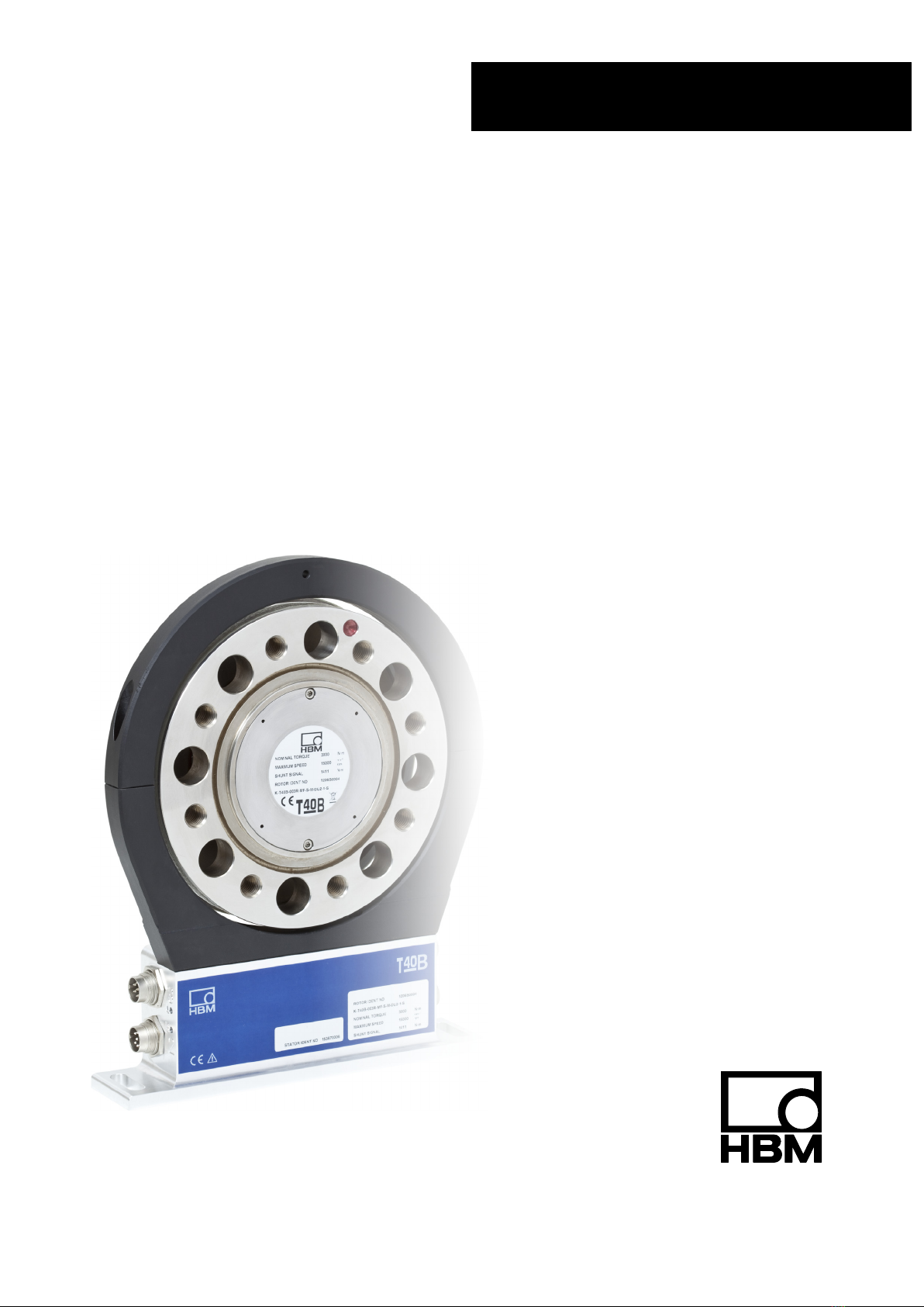
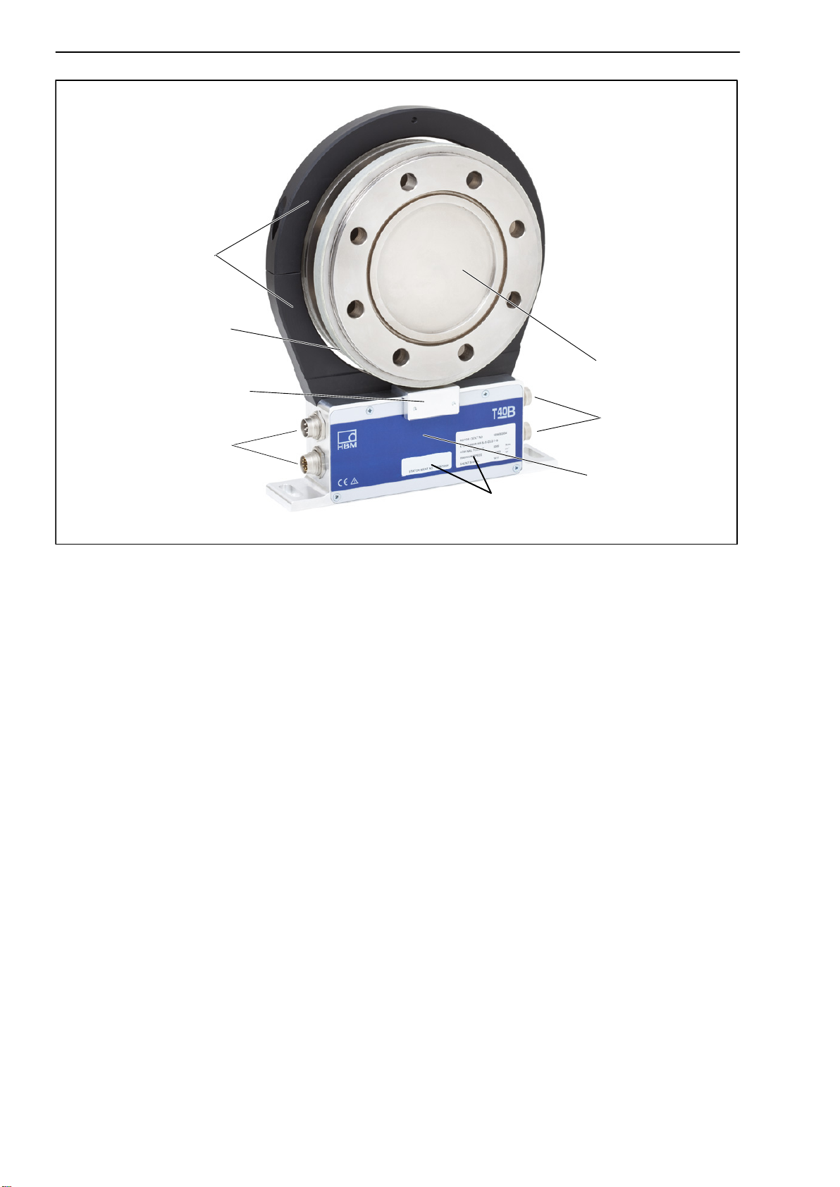
HBM T40B User manual

A3452-5.0 en/de
Torque flange
Drehmoment‐Messflansch
T40B
Mounting Instructions
Montageanleitung

English Page 3 - 43.................................................
Deutsch Seite 45 - 85...............................................
Dimensions/Abmessungen Page/Seite 87 - 1 16......................

3
T40B
A3452-5.0 en/de HBM
Contents Page
English
Safety instructions 5..............................................
1 Markings used 8...............................................
1.1 Symbols on the transducer 8................................
1.2 The markings used in this document 8........................
2 Application 9..................................................
3 Structure and mode of operation 10..............................
4 Mechanical installation 13.......................................
4.1 Important precautions during installation 13....................
4.2 Conditions on site 14........................................
4.3 Installation orientation 14....................................
4.4 Installation options 14.......................................
4.4.1 Installation without dismantling the antenna ring 15........
4.4.2 Installation with subsequent stator mounting 16...........
4.5 Mounting the rotor 17.......................................
4.6 Installing the stator 19.......................................
4.7 Rotational speed measuring system, reference signal (optional) 24
5 Electrical connection 26.........................................
5.1 General information 26......................................
5.2 EMC protection 26..........................................
5.3 Connector pin assignment 27................................
5.4 Supply voltage 30..........................................
6 Shunt signal 31.................................................
7 Functional testing 32............................................
7.1 Rotor status, LED A (upper LED) 32..........................
7.2 Stator status, LED B (lower LED) 33..........................
8Load‐carrying capacity 34.......................................
9 Maintenance 35.................................................
10 Waste disposal and environmental protection 35..................
11 Ordering numbers, accessories 36...............................
12 Specifications 37...............................................
13 Supplementary technical information 44..........................

T40B
4
A3452-5.0 en/deHBM
Safety instructions
Appropriate use
The T40B torque flange is used exclusively for torque, angle of rotation and
power measurement tasks within the load limits stipulated in the specifica-
tions. Any other use is not the designated use.
Stator operation is only permitted when the rotor is installed.
The torque flange may only be installed by qualified personnel in compliance
with the specifications and with the safety requirements and regulations of
these mounting instructions. It is also essential to observe the applicable legal
and safety regulations for the application concerned. The same applies to the
use of accessories.
The torque flange is not intended for use as a safety component. Please also
refer to the section: “Additional safety precautions". Proper and safe operation
requires proper transportation, correct storage, siting and mounting, and care-
ful operation.
Load‐carrying capacity limits
The data in the technical data sheets must be complied with when using the
torque flange. In particular, the respective maximum loads specified must
never be exceeded. The values stated in the specificationsmust not be
exceeded, for example, for
limit torque,
longitudinal limit force, lateral limit force or limit bending moment,
torque oscillation width,
breaking torque,
temperature limits,
the limits of the electrical load‐carrying capacity.
Use as a machine element
The torque flange can be used as a machine element. When used in this
manner, it must be noted that, to favor greater sensitivity, the transducer is not
designed with the safety factors usual in mechanical engineering. Please refer
here to the section “Load‐carrying capacity limits" and to the specifications.
Accident prevention
According to the prevailing accident prevention regulations, once the trans-
ducers have been mounted, a covering agent or cladding has to be fitted as
follows:
The covering agent or cladding must not be free to rotate.

5
T40B
A3452-5.0 en/de HBM
The covering agent or cladding should prevent squeezing or shearing and
provide protection against parts that might come loose.
Covering agents and cladding must be positioned at a suitable distance or
be so arranged that there is no access to any moving parts within.
Covering agents and cladding must still be attached even if the moving
parts of the torque flange are installed outside people's movement and
working range.
The only permitted exceptions to the above requirements are if the torque
flange is already fully protected by the design of the machine or by existing
safety precautions.
Additional safety precautions
The torque flange cannot (as a passive transducer) implement any (safety‐rel
evant) cutoffs. This requires additional components and constructive meas-
ures for which the installer and operator of the plant is responsible. The layout
of the electronics conditioning the measurement signal should be such that
measurement signal failure does not cause damage.
The scope of supply and performance of the transducer covers only a small
area of torque measurement technology. In addition, equipment planners,
installers and operators should plan, implement and respond to safety engin-
eering considerations in such a way as to minimize residual dangers. Pertin-
ent national and local regulations must be complied with.
General dangers of failing to follow the safety instructions
The torque flange corresponds to the state of the art and is fail‐safe. Trans-
ducers can give rise to residual dangers if they are incorrectly operated or
inappropriately mounted, installed and operated by untrained personnel.
Every person involved with siting, starting‐up, operating or repairing a torque
flange must have read and understood the mounting instructions and in partic-
ular the technical safety instructions. The transducers can be damaged or
destroyed by non‐designated use of the transducer or by non‐compliance with
the mounting and operating instructions, these safety instructions or any other
applicable safety regulations (BG safety and accident prevention regulations),
when using the transducers. Transducers can break, particularly in the case of
overloading. The breakage of a transducer can also cause damage to prop-
erty or injury to persons in the vicinity of the transducer.
If the torque flange is not used according to the designated use, or if the
safety instructions or specifications in the mounting and operating instructions
are ignored, it is also possible that the transducer may fail or malfunction, with
the result that persons or property may be adversely affected (due to the
torques acting on or being monitored by the torque flange).

T40B
6
A3452-5.0 en/deHBM
Conversions and modifications
The transducer must not be modified from the design or safety engineering
point of view except with our express agreement. Any modification shall
exclude all liability on our part for any damage resulting therefrom.
Selling on
If the torque flange is sold on, these mounting instructions must be included
with the torque flange.
Qualified personnel
Qualified personnel means persons entrusted with siting, mounting, starting‐
up and operating the product, who possess the appropriate qualifications for
their function.
This includes people who meet at least one of the three following require-
ments:
- Knowledge of the safety concepts of automation technology is a require-
ment and as project personnel, you must be familiar with these concepts.
- As automation plant operating personnel, you have been instructed how to
handle the machinery. You are familiar with the operation of the equipment
and technologies described in this documentation.
- As system startup engineers or service engineers, you have successfully
completed the training to qualify you to repair the automation systems. You
are also authorized to activate, ground and label circuits and equipment in
accordance with safety engineering standards.

7
T40B
A3452-5.0 en/de HBM
1 Markings used
1.1 Symbols on the transducer
Symbol:
Meaning: Read and note the data in this manual
Symbol:
Meaning: CE mark
The CE mark enables the manufacturer to guarantee that the product com-
plies with the requirements of the relevant EC directives (the Declaration of
Conformity can be found on the HBM website at www.hbm.com under
HBMdoc).
1.2 The markings used in this document
Important instructions for your safety are specifically identified. It is essential
to follow these instructions in order to prevent accidents and damage to prop-
erty.
Symbol Significance
This marking warns of a potentially
dangerous situation in which failure to
comply with safety requirements can result
in death or serious physical injury.
CAUTION
This marking warns of a potentially
dangerous situation in which failure to
comply with safety requirements can result
in slight or moderate physical injury.
NOTE
This marking draws your attention to a
situation in which failure to comply with
safety requirements can lead to damage to
property.
Important
This marking draws your attention to
important information about the product or
about handling the product.
Tip This marking indicates application tips or
other information that is useful to you.

T40B
8
A3452-5.0 en/deHBM
SignificanceSymbol
This marking draws your attention to
information about the product or about
handling the product.
Emphasis Italics are used to emphasize and highlight
texts.
2 Application
The T40B torque flange measures static and dynamic torques on stationary
and rotating shafts. Test beds can be extremely compact because of the short
construction of the transducer. This offers a very wide range of applications.
The T40B torque flange is reliably protected against electromagnetic interfer-
ence. It has been tested with regard to EMC according to the relevant
European standards, and carries the CE mark.

9
T40B
A3452-5.0 en/de HBM
3 Structure and mode of operation
The torque flange consists of two separate parts: the rotor and the stator. The
rotor comprises the measuring body and the signal transmission elements.
Strain gauges (SGs) are installed on the measuring body. The rotor electron-
ics for transmitting the bridge excitation voltage and the measurement signal
are located centrally in the flange. The transmitter coils for contactless trans-
mission of excitation voltage and measurement signal are located on the
measuring body's outer circumference. The signals are sent and received by
a separable antenna ring. The antenna ring is mounted on a housing that con-
tains the electronics for voltage adaptation and the signal conditioning.
Connector plugs for the torque and speed signals, the voltage supply and
digital output, are located on the stator. The antenna segments (ring) should
be mounted more or less concentrically around the rotor (see chapter 4).
Antenna segments
Rotor
Connector plugs
Stator housing
Type plate
Connector plugs
Fig. 3.1: Mechanical construction without a rotational speed measuring system
The speed sensor is mounted on the stator in Option 6 with a rotational speed
measuring system. The rotational speed is measured magnetically via an
AMR sensor and a magnetic ring. The magnetic ring for measurement of rota-
tional speed is welded to the flange.

T40B
10
A3452-5.0 en/deHBM
Antenna segments
Rotor
Connector plugs
Stator housing
Type plate
Connector plugs
Sensor head for measuring
rotational speed
Magnetic ring for measuring
rotational speed
Fig. 3.2: Mechanical construction with a rotational speed measuring system
In the version with a rotational speed measuring system, the transducer can
also be fitted with a sensor head for a reference signal (zero index) for meas-
uring the angle of rotation. The magnet to be used for this is located on the
inner surface of the flange. The sensor head for sampling the reference signal
is located in the bracket above the speed sensor.

11
T40B
A3452-5.0 en/de HBM
Antenna segments
Rotor
Connector plugs
Stator housing
Type plate
Connector plugs
Sensor head for measuring
rotational speed
Magnetic ring for
measuring rotational
speed
Sensor head for
the reference
signal
Fig. 3.3: Mechanical construction with rotational speed measuring system and
sensor for the reference signal (zero index)

T40B
12
A3452-5.0 en/deHBM
4 Mechanical installation
4.1 Important precautions during installation
NOTE
A torque flange is a precision measuring element and therefore needs careful
handling. Dropping or knocking the transducer may cause permanent dam-
age. Make sure that the transducer cannot be overloaded, even while it is
being mounted.
Handle the transducer with care.
Check the effect of bending moments, critical rotational speeds and natural
torsional vibrations, to prevent the transducer being overloaded by
resonance sharpness.
Make sure that the transducer cannot be overloaded.
WARNING
There is a danger of the transducer breaking if it is overloaded. This can
cause danger for the operating personnel of the system in which the
transducer is installed.
Implement appropriate safety measures to avoid overloads and to protect
against resulting dangers.
If alternating loads are expected, use threadlocker (medium strength, e.g.
LOCTITE No. 242) to glue the screws into the counter thread to exclude
prestressing loss due to screw slackening.
Comply with the mounting dimensions to enable correct operation.
An appropriate shaft flange enables the T40B torque flange to be mounted dir-
ectly. It is also possible to mount a joint shaft or relevant compensating ele-
ment directly on the rotor (using an intermediate flange when required). Under
no circumstances should the permissible limits specified for bending
moments, lateral and longitudinal forces be exceeded. Due to the T40B
torque flange's high torsional stiffness, dynamic shaft train changes are kept
to a minimum.

13
T40B
A3452-5.0 en/de HBM
Important
Even if the unit is installed correctly, the zero point adjustment made at the
factory can shift by up to approx. 2% of the sensitivity. If this value is
exceeded, we advise you to check the mounting conditions. If the residual
zero offset when the unit is removed is greater than 1% of the sensitivity,
please send the transducer back to the Darmstadt factory for testing.
4.2 Conditions on site
The T40B torque flange must be protected against coarse dirt particles, dust,
oil, solvents and humidity.
There is wide ranging compensation for the effects of temperature on the out-
put and zero signals of the transducer (see “Specifications" section). If there
are no static temperature ratios, for example, because of the temperature dif-
ferences between the measuring body and the flange, the values given in the
specifications can be exceeded. In this case, ensure static temperature ratios
by cooling or heating, depending on the application. As an alternative, check if
thermal decoupling is possible, e.g. by means of heat radiating elements such
as multiple disc couplings.
4.3 Installation orientation
The torque flange can be installed with any orientation.
With clockwise torque, the output frequency is 60 90 kHz for Option 5,
Code DU2 (Option 5, Code SU2: 10 15 kHz; Option HU2: 240 360kHz).
In conjunction with HBM amplifiers or when using the voltage output, a posit-
ive output signal (0 V +10 V) is present. In the case of the rotational speed
measuring system, an arrow is attached to the stator housing to clearly define
the direction of rotation. If the measurement flange turns in the direction of the
arrow, connected HBM measuring amplifiers deliver a positive output signal.
4.4 Installation options
There are basically two options for mounting the torque flange: with or without
dismantling the antenna ring. We recommend mounting as described in
Chapter 4.4.1. If mounting in accordance with Chapter 4.4.1 is not possible,
(e.g. in the case of subsequent stator replacement), you will have to dismantle
the antenna ring. It is essential in this case to comply with the notes on
assembling the antenna segments (see Chapter 4.4.2).

T40B
14
A3452-5.0 en/deHBM
4.4.1 Installation without dismantling the antenna ring
1. Install rotor 2. Install stator
3. Finish installation of shaft run
Customer
mounting
Support supplied by customer
4. Mount support

15
T40B
A3452-5.0 en/de HBM
4.4.2 Installation with subsequent stator mounting
2. Install shaft train
3. Dismantle antenna segment 4. Install antenna segment
1. Install rotor
4. Mount support
Fan‐type lock
washers
Washers
Support supplied by customer

T40B
16
A3452-5.0 en/deHBM
4.5 Mounting the rotor
Tip
Usually the rotor type plate is no longer visible after installation. This is why
we include with the rotor additional stickers with the important characteristics,
which you can attach to the stator or any other relevant test‐bench compon-
ents. You can then refer to them whenever there is anything you wish to know,
such as the shunt signal. To explicitly assign the data, the identification num-
ber and the size are engraved on the rotor flange, where they can be seen
from outside.
1. Prior to installation, clean the plane faces of the transducer flange and the
counter flange.
For safe torque transfer, the faces must be clean and free from grease.
Use a piece of cloth or paper soaked in solvent. When cleaning, make sure
that you do not damage the transmitter winding or the rotational speed
measuring system.
Without rotational speed
measuring system With rotational speed
measuring system
Flange plane faces
Transmitter winding Rotational speed measuring system
Fig. 4.1: Bolted rotor connection

17
T40B
A3452-5.0 en/de HBM
2. For the bolted rotor connection (see Fig. 4.1), use six or eight DIN EN ISO
4762 hexagon socket screws of the property class stated in Table 4.1, in a
suitable length (dependent on the connection geometry, see Table 4.1 on
page 18).
We recommend DIN EN ISO 4762 socket head cap screws, blackened,
smooth‐headed, permitted size and shape variance in accordance with DIN
ISO 4759, Part 1, product class A.
Important
If alternating loads are expected, use threadlocker (medium strength, e.g.
LOCTITE No. 242) to glue the screws into the counter thread to exclude
prestressing loss due to screw slackening.
3. Fasten all screws with the specified torque (Table 4.1 on page 18).
4. There are eight tapped holes on the rotor for the further mounting of the
shaft run. Also use screws of property class 10.9 or 12.9 and fasten them
with the torque specified in Table 4.1.
Important
If alternating loads are expected, use threadlocker (medium strength, e.g.
LOCTITE No. 242) to glue the screws into the counter thread to exclude
prestressing loss due to screw slackening.
NOTE
Comply with the maximum thread reach as per Table 4.1. Otherwise signific-
ant measurement errors may result from torque shunt, or the transducer may
be damaged.
Measuring range Fastening bolts Prescribed tightening
moment
NVm Z 1) Property class NVm
200 M8
10.9
34
500 M10 67
1 k M10 67
2 k M12 115

T40B
18
A3452-5.0 en/deHBM
Measuring range Prescribed tightening
moment
Fastening bolts
NVmNVmProperty classZ 1)
3 k M12
12.9
135
5 k M14 220
10 k M16 340
Table 4.1:Fastening bolts
1) DIN EN ISO 4762; black/oiled/mtot = 0.125
4.6 Installing the stator
On delivery, the stator has already been installed and is ready for operation.
The upper antenna segment can be separated from the stator, for example,
for maintenance or to facilitate stator mounting.
If your application does not require the stator to be dismantled, proceed as
described in points 2, 5, and 6.
Fan‐type lock washers
Hole for fixing the
antenna segment,
diameter 4.2 or
5.2mm, depending
on maximum
capacity
Stator housing
upper
Antenna segment bolts
with washers (M5)
lower
antenna segments
Fig. 4.2: Bolted connection of the antenna segments on the stator

19
T40B
A3452-5.0 en/de HBM
Stator housing
Lower antenna segment
Antenna wire
T40B without a rotational speed measuring system
T40B with a rotational speed measuring system
Sensor head for measuring rotational speed
Fig. 4.3: Stator housing and lower antenna segment with antenna wire
1. Undo and remove the bolted connections (M5) on the upper antenna seg-
ment.
There are fan‐type lock washers between the antenna segments: make
sure that they do not get lost.
2. Use an appropriate mounting base to install the stator housing in the shaft
train so that there is sufficient opportunity for horizontal and vertical adjust-
ments. Do not fully tighten the bolts yet.
3. Now use two hexagon socket screws to mount the upper antenna segment
removed in Point 1 on the lower antenna segment.
Make sure that the two fan‐type lock washers are inserted between the antenna
segments (these ensure that there is a defined contact resistance)!
Important
To make sure that they function perfectly, the fan‐type lock washers (A5,
3-FST DIN 6798 ZN/galvanized) must be replaced after the bolted antenna
connection has been loosened three times.
4. Now tighten all antenna‐segment bolted connections with a tightening
torque of 5 Nm.

T40B
20
A3452-5.0 en/deHBM
5. Rotational speed measurement without a sensor for the reference signal
(zero index):
Then align the antenna to the rotor in such a way that the antenna
encloses the rotor more or less coaxially and the antenna wire in the
axial direction has the same position as the center of the transmitter
winding on the rotor.
To make this alignment easier, the antenna segment and the transmitter
winding on flange B have the same width. Please comply with the per-
missible alignment tolerances stated in the specifications.
Fig. 4.4: Alignment of the rotor with the stator (without a reference signal
sensor)
Rotational speed measurement with a sensor for the reference signal (zero
index):
Tilt the stator slightly (see Fig. 4.5, left), so that the bracket with the
sensor head for the reference signal (zero index) is between the two
flanges. Now tip the stator over the rotor until the antenna ring com-
pletely covers the flange with the transmitter winding (see Fig. 4.5, right).
Other manuals for T40B
3
Table of contents
Languages:
Other HBM Transducer manuals
Popular Transducer manuals by other brands

Vimar
Vimar ELVOX 46862.001 Installation and operation manual

Simrad
Simrad ES120-7C - INSTALLATION REV A installation manual

Furuno
Furuno TM54 owner's guide

B-band
B-band UST installation manual

JDC Instruments
JDC Instruments SKYWATCH WWS Instructions for use

Baumer
Baumer GCA5 Assembly instruction and safety information