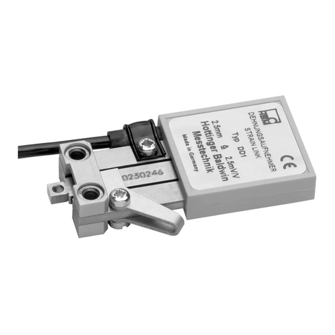
A05717_02_E00_00 29.03.2021 7-0101.0059 HBM: public
Sicherheitshinweise
Lesen Sie die Sicherheitshinweise sorgfältig, bevor Sie das Gerät zum ersten Mal in Betrieb nehmen. Jede
Person, die mit Aufstellung, Inbetriebnahme, Betrieb oder Wartung des Gerätes beauftragt ist, muss mindestens
die für sie relevanten Teile der Sicherheitshinweise gelesen haben. Die Sicherheitshinweise sind Teil des
Produktes. Bewahren Sie diese so auf, dass sie jederzeit für alle Benutzer zugänglich sind. Falls Sie das Gerät
an Dritte weitergeben, geben Sie die Sicherheitshinweise stets zusammen mit den für das Gerät relevanten
Dokumenten weiter.
Bestimmungsgemäße Verwendung
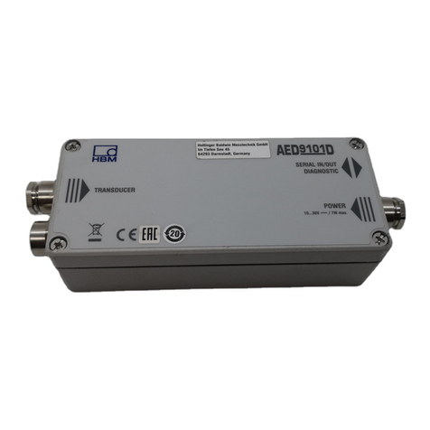
Die digitale Aufnehmerelektronik PAD darf ausschließlich für Messaufgaben und direkt damit verbundene
Steuerungsaufgaben im Rahmen der durch die technischen Daten spezifizierten Einsatzgrenzen verwendet
werden. Jeder andere Gebrauch ist nicht bestimmungsgemäß.
Zur Gewährleistung eines sicheren Betriebes darf das Gerät nur von qualifiziertem Personal und nach den
Angaben in der Bedienungsanleitung betrieben werden.
Die PAD ist nicht zum Einsatz als Sicherheitskomponente bestimmt. Bitte beachten Sie hierzu den Abschnitt
„Zusätzliche Sicherheitsvorkehrungen“. Der einwandfreie und sichere Betrieb setzt sachgemäßen Transport,
fachgerechte Lagerung, Aufstellung und Montage sowie sorgfältige Bedienung voraus
Das Gerät darf nicht unmittelbar an das Stromversorgungsnetz angeschlossen werden. Die Versorgungs
spannung darf 12 bis 30VDC betragen.
Bedingungen am Aufstellungsort
SSorgen Sie dafür, dass im Busbetrieb der max. Strom für Stecker und Buchsen eingehalten wird.
SBeachten Sie die in den technischen Daten angegebenen maximal zulässigen Werte für die max.
Spannungen und Ströme für die Ein- und Ausgänge sowie die Temperaturgrenzen.
SDas Gerät wird ab Werk mit fester Hard‐ und Softwarekonfiguration ausgeliefert. Änderungen sind nur im
Rahmen der in der Dokumentation aufgeführten Möglichkeiten zulässig.
Umbauten und Veränderungen
Das Gerät darf ohne unsere ausdrückliche Zustimmung weder konstruktiv noch sicherheitstechnisch verändert
werden. Insbesondere sind jegliche Reparaturen, Lötarbeiten an den Platinen (Austausch von Bauteilen)
untersagt.
Qualifiziertes Personal
Qualifizierte Personen sind Personen, die mit Aufstellung, Montage, Inbetriebsetzung und Betrieb des Produktes
vertraut sind und über die ihrer Tätigkeit entsprechende Qualifikation verfügen. Dazu zählen Personen, die je
nach Aufgabengebiet mindestens eine der drei folgenden Voraussetzungen erfüllen:
SIhnen sind die Sicherheitskonzepte der Mess- und Automatisierungstechnik bekannt und Sie sind als Projekt
personal damit vertraut.
SSie sind Bedienungspersonal der Mess- oder Automatisierungsanlage und im Umgang mit den Anlagen
unterwiesen. Sie sind mit der Bedienung der in dieser Dokumentation beschriebenen Geräte und Technolo
gien vertraut.
SSie sind Inbetriebnehmer oder für den Service eingesetzt und haben eine Ausbildung absolviert, die Sie zur
Reparatur der Automatisierungsanlagen befähigt. Außerdem haben Sie eine Berechtigung, Stromkreise und
Geräte gemäß den Normen der Sicherheitstechnik in Betrieb zu nehmen, zu erden und zu kennzeichnen.
Restgefahren
Das Gerät entspricht dem Stand der Technik und ist betriebssicher. Von dem Gerät können Restgefahren
ausgehen, wenn es unsachgemäß eingesetzt oder bedient wird. Der Leistungs‐ und Lieferumfang des Gerätes
deckt nur einen Teilbereich der Messtechnik ab. Vor der Inbetriebnahme des Gerätes in einer Anlage ist daher
eine Projektierung und Risikoanalyse vorzunehmen, die alle Sicherheitsaspekte der Mess‐ und Automati
sierungstechnik berücksichtigt, sodass Restgefahren minimiert werden. Bei Geräten, die in Netzwerken arbeiten,
müssen hard‐ und softwareseitig Sicherheitsvorkehrungen getroffen werden, damit ein Leitungsbruch oder
andere Unterbrechungen der Signalübertragung nicht zu undefinierten Zuständen oder Datenverlust in der
Automatisierungseinrichtung führen.
Safety Instructions
Read these safety instructions carefully before operating the device for the first time. Any persons assigned to
install, commission, operate or maintain the device must have read at least the sections of the safety instructions
of relevance to them. Safety instructions form part of the product. Keep them in a safe place so that they are
permanently accessible to all users. If you pass the device on to a third party, always pass the safety instructions
on together with the relevant documents.
Intended use
PAD digital transducer electronics are to be used exclusively for measurement tasks and directly related control
tasks within the application limits detailed in the specifications. Any other use is not the intended use.
In the interests of safety, the device should only be operated by qualified personnel and as described in the
Operating Manual.
PAD is not intended for use as a safety component. Please also refer to the “Additional safety precautions”
section. Proper and safe operation requires proper transportation, correct storage, siting and mounting, and
careful operation.
The device must not be directly connected to the power supply system. The supply voltage must be between 12
and 30VDC.
Conditions at the place of installation
SMake sure that the max. current for plugs and sockets is adhered to in bus mode.
SObserve the maximum permissible values specified in the technical data for the maximum voltages and
currents for the inputs and outputs as well as the temperature limits.
SThe device is supplied ex works with a fixed hardware and software configuration. Changes can only be made
within the range of possibilities described in the documentation.
Conversions and modifications
The design or safety engineering of the device must not be modified without our express consent. In particular,
any repair or soldering work on motherboards (replacement of components) is prohibited.
Qualified personnel
Qualified personnel means persons entrusted with siting, mounting, starting up and operating the product, who
possess the appropriate qualifications for their function. This includes persons who fulfill at least one of the
following three requirements, depending on their area of responsibility:
SThey have knowledge of the safety equipment and procedures of measurement and automation systems, and
are familiar with them as project personnel.
SAs measurement or automation system operating personnel, they have been instructed how to use the
equipment. They are familiar with the operation of the equipment and technologies described in this document.
SAs a commissioning or service engineer, they have successfully completed training on the repair of automa
tion plants. In addition, they are authorized to activate, ground and label circuits and equipment in accordance
with safety engineering standards.
Residual dangers
This is a state-of-the-art device that is safe to operate. However, there may be residual risks if the device is
installed or operated incorrectly. The scope of supply and performance of the device covers only a small area of
measurement technology. Therefore, before starting up the device in a plant, first perform a project planning and
risk analysis, taking into account all the safety aspects of measurement and automation engineering, so that
residual dangers are kept to a minimum. For devices operating in networks, safety precautions must be taken in
terms of both hardware and software, so that an open circuit or other interruptions to signal transmission do not
result in undefined states or loss of data in the automation device.
Note sulla sicurezza
Leggere attentamente le note sulla sicurezza prima di mettere in funzione il dispositivo per la prima volta. Ogni
persona incaricata dell'installazione, della messa in funzione, dell'esercizio o della manutenzione del dispositivo
deve aver letto almeno le parti delle note sulla sicurezza che riguardano le proprie mansioni. Le note sulla
sicurezza sono parte integrante del prodotto. Conservarle in modo che siano sempre accessibili a tutti gli utenti.
In caso di cessione del dispositivo a terzi, consegnare sempre le note sulla sicurezza insieme alla documenta
zione rilevante per il dispositivo.
Uso previsto
L'elettronica digitale per trasduttori PAD può essere utilizzata esclusivamente per compiti di misura e compiti di
controllo ad essi direttamente correlati, nell'ambito dei limiti d'impiego specificati nei dati tecnici. Qualsiasi altro
impiego verrà considerato non conforme.
Allo scopo di garantire un funzionamento senza rischio di guasto, il dispositivo deve essere usato solo da
personale qualificato secondo le specifiche riportate in questo manuale d'istruzione.
La PAD non è concepita per l'uso come componente di sicurezza. Osservare in proposito il paragrafo "Misure di
sicurezza aggiuntive". Il funzionamento corretto e sicuro presuppone il trasporto, l'immagazzinaggio, l'installa
zione e il montaggio conformi, nonché il comando accurato
Il dispositivo non può essere collegato direttamente alla rete di energia elettrica. La tensione di alimentazione
deve essere compresa fra 12 e 30VCC.
Condizioni del luogo d'installazione
SAccertarsi che nell'esercizio con bus la corrente max. per le spine e le prese venga rispettata.
SOsservare i valori ammissibili massimi indicati nei dati tecnici per le tensioni e le correnti max. degli ingressi e
delle uscite e i limiti di temperatura.
SIl dispositivo viene consegnato di fabbrica con configurazione hardware e software predefinita. Sono am
messe modifiche solo nell'ambito delle possibilità documentate nei manuali.
Conversioni e modificazioni
Non è consentito apportare modifiche costruttive al dispositivo né ai relativi sistemi di sicurezza senza il nostro
esplicito consenso. In particolare sono proibiti qualunque riparazione e lavoro di saldatura sulle schede (sostitu
zione di componenti).
Personale qualificato
Per personale qualificato si intendono persone che abbiano familiarità con l'installazione, il montaggio, la messa
in funzione e l'esercizio del prodotto e che dispongano di una qualifica idonea alla loro attività. Tra queste
troviamo persone che soddisfano almeno uno dei tre requisiti seguenti, a seconda del compito:
SHanno conoscenza dei principi di sicurezza della tecnica del sistema di misura e di automazione, nonché
familiarità con gli stessi in qualità di personale responsabile del progetto.
SSono operatori del sistema di misura o di automazione e sono stati istruiti nella gestione dei sistemi. Hanno
familiarità con l'uso dei dispositivi e delle tecnologie descritte in questa documentazione.
SSono incaricati della messa in funzione o degli interventi di assistenza e hanno conseguito una formazione
che li qualifica per la riparazione di sistemi di automazione. Inoltre, sono autorizzati a mettere in funzione, a
mettere a terra e a contrassegnare i circuiti elettrici e i dispositivi, in conformità alle normative relative alla
tecnica di sicurezza.
Pericoli residui
Il dispositivo è allo stato della tecnica ed è senza rischio di guasto. Dal dispositivo possono derivare pericoli
residui se usato e comandato correttamente. Il contenuto della fornitura e le prestazioni del dispositivo coprono
solo una
arte della tecnica di misura. Prima della messa in funzione del dis
ositivo in un im
ianto
ertanto
devono essere eseguite una progettazione e un'analisi dei rischi che considerino tutti gli aspetti di sicurezza
della tecnica di misura e di automazione, così da ridurre al minimo i pericoli residui. In caso di dispositivi che
funzionano in reti, sono necessarie misure di sicurezza hardware e software per impedire che la rottura di un
cavo o altre interruzioni della trasmissione del segnale causino stati non definiti o la perdita di dati nell'impianto
di automazione.
Consignes de sécurité
Lisez attentivement les consignes de sécurité avant de mettre l'appareil en service pour la première fois. Toute
personne chargée de l’installation, de la mise en service, de l’exploitation ou de la maintenance de l’appareil doit
avoir lu au moins les parties des consignes de sécurité qui la concernent. Les consignes de sécurité font partie
intégrante du produit. Conservez-les de façon à ce qu’elles soient toujours accessibles à tous les utilisateurs. Si
vous confiez l'appareil à une tierce personne, remettez-lui systématiquement les consignes de sécurité avec
toute la documentation concernant l’appareil.
Utilisation conforme
L'électronique numérique de capteur PAD ne doit être utilisée que pour des tâches de mesure et pour les
opérations de commande qui y sont directement liées dans le cadre des limites d'utilisation spécifiées dans les
caractéristiques techniques. Toute autre utilisation est considérée comme non conforme.
Pour garantir un fonctionnement de cet appareil en toute sécurité, celui-ci doit uniquement être utilisé par du
personnel qualifié conformément aux instructions du manuel d'emploi.
La PAD n'est pas destinée à être mise en œuvre comme élément de sécurité. Reportez-vous à ce sujet au
paragraphe "Mesures de sécurité supplémentaires". Afin de garantir un fonctionnement parfait et en toute
sécurité, il convient de veiller à un transport, un stockage, une installation et un montage appropriés et d'assurer
un maniement scrupuleux.
L'appareil ne doit pas être raccordé directement au réseau électrique. La tension d'alimentation peut être
comprise entre 12 et 30VDC.
Conditions environnantes à respecter
SAssurez-vous de respecter le courant maximal pour les connecteurs mâles et femelles en mode bus.
SRespectez les valeurs maximales admissibles spécifiées dans les caractéristiques techniques pour les
tensions et courants max. pour les entrées et sorties, ainsi que les limites de température.
SL’appareil est livré à la sortie d'usine avec une configuration matérielle et logicielle fixe. L’apport de mo
difications n’est autorisé que dans les limites des possibilités indiquées dans la documentation.
Transformations et modifications
Il est interdit de modifier l'appareil sur le plan conceptuel ou celui de la sécurité sans accord explicite de notre
part. Il est notamment interdit de procéder soi-même à toute réparation ou soudure sur les circuits imprimés
(remplacement de composants).
Personnel qualifié
Sont considérées comme personnel qualifié les personnes familiarisées avec l'installation, le montage, la mise
en service et l'exploitation du produit, et disposant de la qualification correspondante. En font partie les
personnes remplissant, en fonction de leur domaine de responsabilité, au moins une des trois conditions sui
vantes:
SElles connaissent les concepts de sécurité de la technique de mesure et d'automatisation et les maîtrisent en
tant que chargés de projet.
SElles sont opérateurs de l’installation de mesure ou d'automatisation et ont été formées pour pouvoir utiliser
les installations. Elles savent comment utiliser les appareils et technologies décrits dans le présent document.
SEn tant que personne chargée de la mise en service ou de la maintenance, ces personnes disposent d'une
formation les autorisant à réparer les installations d'automatisation. En outre, ces personnes sont autorisées à
mettre en service, mettre à la terre et marquer des circuits électriques et des instruments selon les normes
des techniques de sécurité.
Dangers résiduels
L'appareil est conforme au niveau de développement technologique actuel et présente une parfaite sécurité de
fonctionnement. L'appareil peut présenter des dangers résiduels s'il est utilisé de manière non conforme. Les
performances de l'appareil et l'étendue de la livraison ne couvrent qu'une partie des techniques de mesure.
Avant la mise en service de l'appareil dans une installation, une configuration et une analyse de risque tenant
compte de tous les aspects de sécurité de la technique de mesure et d'automatisation doivent être réalisées de
façon à minimiser les dangers résiduels. Pour les appareils fonctionnant dans des réseaux, des mesures de
sécurité doivent être prises côté matériel et côté logiciel, afin d’éviter qu’une rupture de câble ou d’autres inter
ruptions de la transmission des signaux n’entraînent des états indéfinis ou la perte de données sur les dispositifs
d'automatisation.
安全提示
。、、
!"。#$%&'()*,,-./,012345。6789:
;,<=#$%> ?@。
规定用途
ABCDEFG PAD
HIJKLAMNOPQRST<STUV WX<。YZC
[&\M。
0,H]^_`abc$%!MN。
PAD
"d(#。ef!"“ghijkl”。mn、o0p$、qr,%>st
&uo0rmRv#。
"w8UVV&'Fxy。HFzOP 12 30(VDC。
安放地点条件
S{f,I|}!~rF。
SefJKAc!MNn&n)Fz、FH*%>。
S)4N#r#。HI?+%OPR。
改造和改装
Iw,%0H2-.,R/rJK;。¡4IF¢£/R
¤V¥(§(#)。
具备资格的人员
5©ª&«¬'q、、r=65 ®©¯。°!±²³
´µ.7v#8:
S¬STr·¸JK¹º,=6»¼)9¬=6½¾。
S¿&STr·¸,=6V^_`a。¬=½¾#?!ÀÁrJK。
S¿&1ÂÃÄ<,=6V^_`a,dÅÆÇ·¸。ÈÉ%h,Êw:ËÌ
,2%bcJKÍ;8F¢rÎ&、Ï,RVÐ=6Ñ%ÍÒ。
潜在危险
ÓÔÕJKÖ×6。µØ"ÙMN"Ú,2d<ÛÜÝIÞß。à
dr=OPáâSTJK*。%ImR8,R»¼M>rãßä,åæSTr
·¸JKà;;,%çÐ?ÝIãß。Ixy!mR,èé#r#;
ijkl,0@ên!}¢!ë!ë"<ìí·¸!)îNBïðAcEñ。
Digital Transducer Electronics
PAD400xA
measure and predict with confidence
HBM Test and Measurement
Tel. +49 6151 803-0 • Fax +49 6151 803-9100
Quick Start Guide


