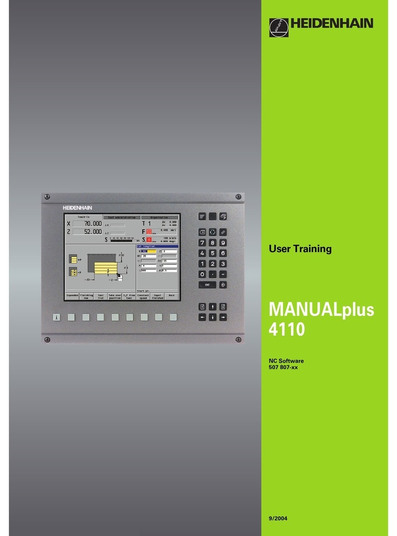
HEIDENHAIN 548431-05 User manual

MANUALplus 620
User’s Manual
NC Software
548431-05
English (en)
12/2017


Overview of keys

Overview of keys
4HEIDENHAIN | MANUALplus 620 | User's Manual | 12/2017
Controls and displays
Keys
If you are using a control with touch operation, you can
replace some keystrokes with hand gestures.
Further information: "Operating the Touchscreen",
Page 83
Keys on visual display unit
Key Function
Switches the help graphics
between outside and inside machin-
ing (only during cycle programming)
No function
Selects the function in the display
unit with the soft key selection key
Shift between soft-key rows
Operating mode keys
Key Function
Select machine operating modes:
Machine
Teach-in
Program run
Reference
Select programming operating
modes:
smart.Turn
DINplus – Unit mode
ISO Mode
Simulation
AWG
Select tool data and technology
data:
Tool editor
Technology editor
Select Organization operating
mode:
Machine parameters
Transfer
Project management
Network connection
Diagnostics
Numeric keypad
Key Function
Number keys 0 to 9:
Enter numbers
Operate the menu
Insert a decimal point
Switch over between positive and
negative values
Cancel the dialog
Navigate to the top of the menu
Escape
Confirm a dialog
Create a new NC block in the
editor
Insert
Delete the selected range
Delete Block
Erase the character to the left of the
cursor
BACKSPACE
Clear error messages in the
Machine operating modes
Clear Entry
Enable dialog input fields for further
input
Confirm the entry
Enter

HEIDENHAIN | MANUALplus 620 | User's Manual | 12/2017 5
Navigation keys
Key Function
Move the cursor up or down
Move the cursor to the left or to the
right
Scroll back or forward one screen or
dialog page
Page Up and
Page Down
Go to beginning of program/list or
end of program/list
smart.Turn keys
Key Function
Go to the next form
Go to next or previous group
Special keys
Key Function
Open the error window
Error
Start the integrated calculator
Calculator
Show additional information in
the parameter editor
Call the TURNguide
Information
Select alternative input
Activate the alphabetic keyboard
Go to
Print Screen
DIADUR
Machine operating panel
Key Function
Start or stop machining
Feed stop
Stop the spindle
Switch on the spindle
Spindle jog
The spindle rotates as long as you
press the key.
Move the axes, e.g. in +X or +Y
direction
Change the spindle
(machine-dependent)

Overview of keys
6HEIDENHAIN | MANUALplus 620 | User's Manual | 12/2017
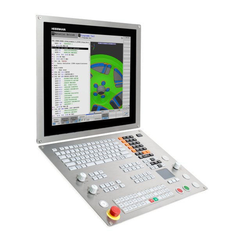
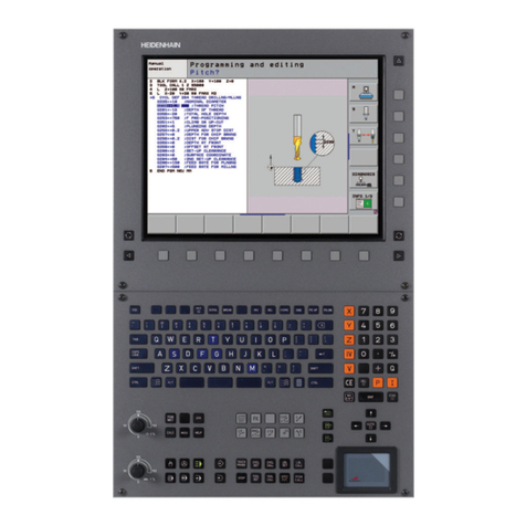
Operating panel of the control
MC 7410T
MC 8420T

Fundamentals

Fundamentals | Notes in this documentation
8HEIDENHAIN | MANUALplus 620 | User's Manual | 12/2017
Notes in this documentation
Safety precautions
Comply with all safety precautions indicated in this document and
in your machine tool builder's documentation!
Precautionary statements warn of hazards in handling software
and devices and provide information on their prevention. They are
classified by hazard severity and divided into the following groups:
DANGER
Danger indicates hazards for persons. If you do not follow the
avoidance instructions, the hazard will result in death or severe
injury.
WARNING
Warning indicates hazards for persons. If you do not follow the
avoidance instructions, the hazard could result in death or
serious injury.
CAUTION
Caution indicates hazards for persons. If you do not follow the
avoidance instructions, the hazard could result in minor or
moderate injury.
NOTICE
Notice indicates danger to material or data. If you do not follow
the avoidance instructions, the hazard could result in things
other than personal injury, such as property damage.
Sequence of information in precautionary statements
All precautionary statements comprise the following four sections:
Signal word indicating the hazard severity
Type and source of hazard
Consequences of ignoring the hazard, e.g.: "There is danger of
collision during subsequent machining operations"
Escape – Hazard prevention measures

Fundamentals | Notes in this documentation
HEIDENHAIN | MANUALplus 620 | User's Manual | 12/2017 9
Informational notes
Observe the informational notes provided in these instructions to
ensure reliable and efficient operation of the software.
In these instructions, you will find the following informational
notes:
The information symbol indicates a tip.
A tip provides additional or supplementary information.
This symbol prompts you to follow the safety
precautions of your machine tool builder. This symbol
also indicates machine-dependent functions. Possible
hazards for the operator and the machine are described
in the machine manual.
The book symbol represents a cross reference to
external documentation, e.g. the documentation of your
machine tool builder or other supplier.
Would you like to see any changes made, or have you found
any errors?
We are continuously striving to improve our documentation for you.
Please help us by sending your requests to the following e-mail
address:

Fundamentals | Software and features
10 HEIDENHAIN | MANUALplus 620 | User's Manual | 12/2017
Software and features
This manual describes functions that are available in the control
with NC software number 548431-05.
The programming of smart.Turn and DIN PLUS are not included in
this manual. These functions are described in the User's Manual
for smart.Turn and DIN PLUS Programming (ID 685556-xx). Please
contact HEIDENHAIN if you need this user's manual.
The machine manufacturer adapts the usable features of the
control to his machine by setting the machine parameters. Some
of the functions described in this manual may not be among the
features possible on your machine tool.
Control functions that may not be available on your machine
include:
Positioning of spindle (M19) and driven tool
Machining with the C or Y axis
Machining with the B axis
In order to find out about the specific support for your machine,
please contact the machine manufacturer.
Many machine manufacturers and HEIDENHAIN offer programming
courses. We recommend these courses as an effective way of
improving your programming skill and sharing information and ideas
with other users of the control.
HEIDENHAIN also offers the DataPilot MP 620 or DataPilot CP 640
software for PCs, which is designed for use with the respective
control. The DataPilot is suitable for both shop-floor programming
as well as off-location program creation and testing. It is also
ideal for training purposes. The DataPilot can be run on PCs with
WINDOWS operating systems.
Intended place of operation
The control complies with the limits for a Class A device in
accordance with the specifications in EN 55022, and is intended for
use primarily in industrially-zoned areas.
Legal information
This product uses open-source software. Further information is
available on the control under:
Organization mode of operation
LICENSE INFO soft key
Fundamentals | Software and features
HEIDENHAIN | MANUALplus 620 | User's Manual | 12/2017 11
New functions
New functions of software 548328-04
In the Simulation submode, the current contour description (of
workpiece blank and finished part) can be mirrored and saved.
These contours can be reinserted in the smart.Turn mode of
operation, see "Saving the generated contour in Simulation
submode", Page 549
On machines with counter spindle, the workpiece spindle can
be selected in the TSF menu, see "Expanded form view for
machines with counter spindle", Page 125
On machines with counter spindle, its datum can be shifted,
see "Expanded form view for machines with counter spindle",
Page 125
The user documentation is also available in the context-sensitive
help system TURNguide, see "Application", Page 76
You can make your own project folder in the project
management so that you can centrally manage associated files,
see "Project management", Page 167
With a manual change system it is possible to insert tools that
are not in the turret during program run, see "Manual change
systems", Page 574
The Teach-in submode also provides cycles for engraving, see
"Engraving, axial", Page 391
During tool data backup, you can select in a dialog window
the data to be saved or restored, see "Tool backup data",
Page 665
The G30 function is now available for converting G
functions, M functions or spindle numbers, as well
as for mirroring traverse paths and tool dimensions,
see the smart.Turn and DIN Programming User's Manual
The Traversing to a fixed stop G916 function is available
for transferring the workpiece to the second traversable
spindle or for pressing the tailstock against the workpiece,
see the smart.Turn and DIN Programming User's Manual
The G925 function makes it possible to define and
monitor the maximum contact force for an axis.
This function can be applied to use the counter
spindle as a mechatronic tailstock, for example,
see the smart.Turn and DIN Programming User's Manual
Controlled parting using servo-lag monitoring
G917 can be activated to help prevent collisions
caused by incomplete parting processes,
see the smart.Turn and DIN Programming User's Manual
The spindle synchronization option G720 synchronizes
the shaft speeds of two or more spindles so that they
rotate synchronously with a gear ratio or a defined offset,
see the smart.Turn and DIN Programming User's Manual

Fundamentals | Software and features
12 HEIDENHAIN | MANUALplus 620 | User's Manual | 12/2017
In combination with the synchronization G720 of main
spindle and tool spindle, the new Hobbing G808 cycle
is available for milling external teeth and profiles,
see the smart.Turn and DIN Programming User's Manual
With G924, a Fluctuating speed can
be programmed to prevent resonance,
see the smart.Turn and DIN Programming User's Manual

Fundamentals | Software and features
HEIDENHAIN | MANUALplus 620 | User's Manual | 12/2017 13
New functions of software 548328-05 and 54843x-01
In the Organization mode of operation, you can grant or restrict
access to the control by using the EXTERNAL ACCESS soft key,
see "Organization mode of operation", Page 604
The pocket calculator can now be activated in each application
and also remains active after a change in operating modes.
With the GET CURRENT VALUE and CONFIRM VALUE soft keys,
numerical values can be fetched from the active input field and
transferred to the active input field, see "Calculator functions",
Page 67
Tool touch probes can be calibrated in the Setup menu, see
"Calibrating the tool touch probe", Page 126
The workpiece datum can also be set in the direction of the Z
axis using a touch probe, see "Machine setup", Page 121
In Teach-in submode the RI and RK workpiece blank oversizes
have been introduced for finishing operations with the recess
turning cycles, see "Radial recess turning, finishing—Expanded",
Page 291
The oversizes RI and RK for the workpiece blank were
introduced for finishing in the recess-turning units and in Cycle
G869, see the smart.Turn and DIN Programming User's Manual
On machines with a B axis it is also possible to drill, bore,
and mill in oblique planes. In addition to this, the B axis
enables you to use tools even more flexibly during turning,
see the smart.Turn and DIN Programming User's Manual
The control provides numerous touch
probe cycles for various applications,
see the smart.Turn and DIN Programming User's Manual:
Calibrating a touch trigger probe
Measuring circles, circle segments, angle and position of the
C axis
Misalignment compensation
Single-point and double-point measurement
Finding a hole or stud
Zero point setting in the Z or C axis
Automatic tool measurement
The new TURN PLUS function automatically
generates NC programs for turning and milling
operations based on a fixed machining sequence,
see the smart.Turn and DIN Programming User's Manual
G940 provides a way to calculate the tool lengths
in the basic (definition) position of the B axis ,
see the smart.Turn and DIN Programming User's Manual
For machining operations that require rechucking, you can
define a separation point on the contour description with G44,
see the smart.Turn and DIN Programming User's Manual
G927 enables you to convert tool lengths to
the reference position of the tool (B axis = 0),
see the smart.Turn and DIN Programming User's Manual
Recesses that were defined with G22 can be
machined with the new Cycle G870 ICP Recessing,
see the smart.Turn and DIN Programming User's Manual

Fundamentals | Software and features
14 HEIDENHAIN | MANUALplus 620 | User's Manual | 12/2017
New functions of software 54843x-02
In the ICP editor submode, the Shift the datum miscellaneous
function was introduced, see "Datum shift", Page 434
In ICP contours, fit dimensions and inside threads can now be
calculated using an input form, see "Fits and internal threads",
Page 429
In the ICP editor submode, the miscellaneous functions
Duplicate in linear/Duplicate in circular series/Duplicate by mirroring
were introduced, see "Duplicating a contour section in linear
series", Page 435
The system time can be set using an input form, see "Displaying
operating times", Page 127
The parting cycle G859 was expanded by the parameters K, SD
and U, see "Cut off", Page 308
The ICP recess turning cycles allow defining an approach angle
and a departure angle, see "Radial ICP recess turning, finishing",
Page 299
With TURN PLUS you can now also create programs for
machining on the counter spindle and for multipoint tools,
see the smart.Turn and DIN Programming User's Manual
It is also possible to select a milling
contour in G797 Area milling,
see the smart.Turn and DIN Programming User's Manual
The parameter Y was added to G720,
see the smart.Turn and DIN Programming User's Manual
The parameters O and U were added to G860,
see the smart.Turn and DIN Programming User's Manual

Fundamentals | Software and features
HEIDENHAIN | MANUALplus 620 | User's Manual | 12/2017 15
New functions of software 54843x-03
In the Teach-in submode, the parameter RB was added to the
cycles Axial figure, Radial figure, ICP contour axial and ICP
contour radial, see "Axial figure", Page 367
In the Teach-in submode, the parameters SP and SI were added
to all tapping cycles, see "Drilling cycles", Page 342
In the Simulation submode, the 3-D view provides additional
features, see "3-D view", Page 541
Tool control graphics were introduced in the Tool editor mode
of operation, see "Tool control graphics", Page 565
An ID number can be entered directly in the turret list, see
"Editing the turret list", Page 113
The tool list provides additional filter options, see "Sorting and
filtering the tool list", Page 562
The Transfer submode provides enhanced tool backup
functionality, see "Transferring tool data", Page 664
The Transfer submode provides enhanced tool import
functionality, see "Importing tool data from the CNC PILOT
4290", Page 674
The Set axis value menu item now enables you to define
offset values for shifts using G53, G54, and G55, see "Defining
offsets", Page 122
Load monitoring was introduced in the Program run submode,
see "Load monitoring (optional)", Page 155
The definition of skip levels was introduced in the Program run
submode, see "Program execution", Page 146
A function was introduced to query information on the tool
status, see "Tool life monitoring", Page 119, see "Editing tool
life data", Page 569
A user parameter was introduced to enable you to activate
and deactivate the software limit switches for the Simulation
submode, see "List of machine parameters", Page 608
A user parameter was introduced to enable you to suppress
the error message for the software limit switches, see "List of
machine parameters", Page 608
A user parameter was introduced to enable you to use NC-Start
for executing a tool change programmed in the TSF menu, see
"List of machine parameters", Page 608
A user parameter was introduced to divide the TSF menu into
separate dialogs, see "List of machine parameters", Page 608
A user parameter was introduced to enable you to inhibit the
G59 datum shift automatically output in TURN PLUS, see "List of
machine parameters", Page 608
The parameter WE was added to G32,
see the smart.Turn and DIN Programming User's Manual
The parameters U, V, and W were added to G51, G56, and G59,
see the smart.Turn and DIN Programming User's Manual
Parameters ensuring maximum compatibility with the
ICP contour description were added to G0, G1, G12/G13,
G101, G102/G103, G110, G111, G112/G113, G170,
G171, G172/G173, G180, G181, and G182/G183,
see the smart.Turn and DIN Programming User's Manual

Fundamentals | Software and features
16 HEIDENHAIN | MANUALplus 620 | User's Manual | 12/2017
The parameter C was added to G808,
see the smart.Turn and DIN Programming User's Manual
The parameter U was added to G810 and G820,
see the smart.Turn and DIN Programming User's Manual
The parameter D was added to G4 and G860,
see the smart.Turn and DIN Programming User's Manual
The parameter B was added to G890,
see the smart.Turn and DIN Programming User's Manual
The parameter RB was added to the units G840 "Contour
milling, figures" and G84X "Pocket milling, figures",
see the smart.Turn and DIN Programming User's Manual
The parameters SP and SI were added to all tapping units,
see the smart.Turn and DIN Programming User's Manual
G48 was introduced to allow limiting the
rapid traverse rate for rotary and linear axes,
see the smart.Turn and DIN Programming User's Manual
G53, G54, and G55 were introduced
for zero-point shifts using offset values,
see the smart.Turn and DIN Programming User's Manual
The functions for superimposing axis movements
Eccentric turning G725, Eccentric transition
G726, and Non-circular X G727 were introduced,
see the smart.Turn and DIN Programming User's Manual
The load monitoring functions G995 "Monitoring zone
definition" and G996 "Type of load monitoring" were introduced,
see the smart.Turn and DIN Programming User's Manual
The AWG submode now also supports
tools with quick-change tool holders,
see the smart.Turn and DIN Programming User's Manual
A tree view is available in the smart.Turn operating mode,
see the smart.Turn and DIN Programming User's Manual
Skip levels can be defined in the smart.Turn operating mode,
see the smart.Turn and DIN Programming User's Manual
A function was introduced to output information on the tool
status, see the smart.Turn and DIN Programming User's Manual

Fundamentals | Software and features
HEIDENHAIN | MANUALplus 620 | User's Manual | 12/2017 17
New functions of software 54843x-04
In the Simulation submode, the Dimensioning function was
introduced, see "Dimensioning", Page 550
In the Simulation submode, the Save contour function was
enhanced, see "Saving the contour", Page 549
In the Simulation submode, display of the B head is supported,
see "Depicting the tool holder in Simulation submode",
Page 539
In the Teach-in submode, the workpiece blank is also redrawn
with centric drilling, see "Contour follow-up in Teach-in
submode", Page 174
In the Teach-in submode, the GK parameter can now also be
negatively programmed with taper threads, see "Thread and
undercut cycles", Page 312
In the ICP editor submode, contour groups are supported.
The number of the contour group is displayed at top left in the
graphic window, see "Contour groups", Page 528
Machine parameter recessFinishing (602414) is now evaluated
in the Teach-in submode, so that the possibilities 1: Divide
floor element and 2: Move through and lift-off are also
available here, see "Recessing cycles", Page 253
New convertICP (602023) machine parameter for converting
ICP contours, see "List of machine parameters", Page 608
The machining parameters for approach and departure have
been adapted, see "List of machine parameters", Page 608
The Reamer tool type (type 43 from CNC PILOT 4290) is
supported, see "Tool types", Page 558
The navigation and the tool parameters view were improved in
the tool list, see "Navigating in the tool list", Page 561
The Pocket Type tool parameter was introduced, see "General
tool parameters", Page 576
Magazine pocket systems are supported, see "Editing the
magazine list", Page 115
Tool compensations can be entered with the handwheel or
in a dialog, see "Tool compensation", Page 136, see "Tool
compensation in Teach-in submode", Page 179
When configuring the C axis, you can set a defined value on the
current position, see "Setting C-axis values", Page 125
It is possible to sequentially run several main programs
automatically. A program list is generated for this purpose. With
each program, you can now specify how often it is run before
the next program is started, see "Automatic job", Page 150
The continuous run status is also kept if the control is restarted
in the Program run submode, see "Program run submode",
Page 142
Programs can be deleted in the file manager even though they
are selected in the Program run submode, after program block
display is deselected, see "Program run submode", Page 142
For systems with a C axis, the position display in the machine
data display (axis letter and index) can be configured by the
machine manufacturer
The functions G0, G1, and G701 have been enhanced with
parameters for auxiliary axes

Fundamentals | Software and features
18 HEIDENHAIN | MANUALplus 620 | User's Manual | 12/2017
Programming with variables in the smart.Turn
operating mode is now possible with soft keys,
see the smart.Turn and DIN Programming User's Manual
The number of local variables was increased from 30 to 99,
see the smart.Turn and DIN Programming User's Manual
In the NC program, the status of shifts G920/G921
can now be queried with the variables #n920(G),
see the smart.Turn and DIN Programming User's Manual
In the smart.Turn operating mode, the number of an
M function can now also be defined with a variable
see the smart.Turn and DIN Programming User's Manual
In the smart.Turn operating mode, up
to four contour groups are supported,
see the smart.Turn and DIN Programming User's Manual
In a program generated in the AWG submode, the tool traverses
to the tool change position after the parting working step,
see the smart.Turn and DIN Programming User's Manual
In a program generated in the AWG submode, machining is
now also possible with simplified geometry programming,
see the smart.Turn and DIN Programming User's Manual
The TURN PLUS function can now also be used in INCH mode,
see the smart.Turn and DIN Programming User's Manual
The CW parameter was changed into a user
prompt: Reverse the tool 0: No 1: Yes,
see the smart.Turn and DIN Programming User's Manual
The Q parameter in G99 is supported,
see the smart.Turn and DIN Programming User's Manual
The DO parameter was added to the G860 Contour
recess in ICP and G860 Contour recess, direct cycles.
see the smart.Turn and DIN Programming User's Manual
The Type of tool access" parameter can now also be modified
via the machining parameters in the smart.Turn operating
mode, see the smart.Turn and DIN Programming User's Manual
The G154 Short path in C function was introduced,
see the smart.Turn and DIN Programming User's Manual
The parameter O Flow was added to G741,
see the smart.Turn and DIN Programming User's Manual
Parameter A of G845 has been enhanced with the input
option for pilot drilling in the reference point of the figure,
see the smart.Turn and DIN Programming User's Manual
The input range for Boring depth in
the G74 drilling cycle was expanded,
see the smart.Turn and DIN Programming User's Manual
No error message is displayed anymore in the
paraxial turning cycles if the task is to be carried
out with the secondary cutting edge of the tool,
see the smart.Turn and DIN Programming User's Manual
Machining parameters are displayed in millimeters or inches
according to the CfgUnitOfMeasure parameter (101100)

Fundamentals | Software and features
HEIDENHAIN | MANUALplus 620 | User's Manual | 12/2017 19
New functions of software 54843x-05
The control displays error messages of different classes in
various colors, see "Display of errors", Page 71
If the programmed spindle speed is displayed in red in the
machine data display, a limitation is active and the programmed
nominal value will not be reached, see "Machine data display",
Page 102
Additional functions were added to the machine data display,
e.g. a handwheel symbol and the C axis datum shift, see
"Machine data display", Page 102
To restart the control only, the RESTART soft key was added, see
"Switch-off", Page 95
In Teach-in submode, the input range for the Angle in the B
axis BW cycle parameter in the T,S,F dialog was extended to
four decimal places.
In Teach-in submode and in DIN Programming, the input range
for Thread pitch was extended to 4 decimal places.
In Simulation submode, the Mark the machining area
miscellaneous function was added, see "Mark the machining
area", Page 552
In Simulation submode, the C0 – Marking on workpiece/3D
miscellaneous function was added, see "C0 – Marking on
workpiece/3D", Page 553
In Simulation submode, a new status display was added, see
"Status display", Page 537
In 3-D simulation, tool holder display is now supported, see "3-D
simulation in Simulation submode", Page 554
In Program run submode, it is possible to display the variables
defined in the PROGRAM HEAD program section, see "Program
execution", Page 146
In Tool editor operating mode, you can edit the diagnostic
bits displayed in the open tool dialog, see "Diagnostic bits",
Page 570
In Tool editor operating mode, the Max. shaft speed NMX
tool parameter was added, see "General tool parameters",
Page 576

Fundamentals | Software and features
20 HEIDENHAIN | MANUALplus 620 | User's Manual | 12/2017
In Tool editor operating mode, the Tool radius 2 R2 and Tool
radius 2 oversize DR2 tool parameters were added for standard
milling cutters, see "Standard milling tools", Page 589
In Tool editor operating mode, the CA1 and CA2 tool
parameters (calibration values) were added for 3-D touch
probes, see "Touch probes", Page 594
In Tool editor operating mode, the Halter Tiefe WHT and
Versatz für Tiefe TOF parameters were added to the tool
holder dialogs, see "Holder editor", Page 571
The Delete all soft key was added to the Table of the tool
holder, see "Holder editor", Page 571
The Save and Cancel soft keys were added to the Tool text list,
see "Tool texts", Page 565
The Turret assignment and Magazine list now display the LA,
XL and ZL columns.
By pressing the arrow keys, you can navigate to the next or
previous column within the Turret assignment and Magazine
list.
In order to allow you to transfer screenshots (created with
the PRT SC key) in Transfer operating mode, the Select TNC:
soft key was added to the Service section, see "Transferring
programs (files)", Page 659
To check the usable length of the cutting edge for finishing
operations, the checkCuttingLength (602322) machine
parameter was added, see "List of machine parameters",
Page 608
In order to suppress the Residual material due to cutting
edge geometry! warning, we added the suppressRestMatWar
(201010) machine parameter, see "List of machine parameters",
Page 608
To automatically load the program last used in Program run
submode, the autoPgmSelect (601814) machine parameter
was added, see "List of machine parameters", Page 608, see
"Loading a program", Page 142
The DefaultG14 machine parameter was extended to include
additional traverse options to the G14 tool change position, see
"List of machine parameters", Page 608
With the G function for engraving, you can
engrave the date and time using variables,
see the smart.Turn and DIN Programming User's Manual
Contents of variables can be converted to string variables,
see the smart.Turn and DIN Programming User's Manual
Touchscreen operation is supported, see "Operating the
Touchscreen", Page 83
Operation of the new HR 520 and HR 550FS electronic
handwheels is supported, see "Configuring the HR 550FS
wireless handwheel", Page 128
The machine tool builder can extend the machine data display to
5 lines on 19" screens, see "Machine data display", Page 102
On 19” screens, the Transfer machine
soft key is located in the first soft-key row,
see the smart.Turn and DIN Programming User's Manual
This manual suits for next models
1
Table of contents
Other HEIDENHAIN Control Panel manuals

HEIDENHAIN
HEIDENHAIN POSITIP 8000 User manual

HEIDENHAIN
HEIDENHAIN MANUALPLUS 4110 User manual

HEIDENHAIN
HEIDENHAIN ITNC 530 - CYCLE PROGRAMMING User manual

HEIDENHAIN
HEIDENHAIN TNC 640 User manual

HEIDENHAIN
HEIDENHAIN ITNC 530 - CONVERSATIONAL PROGRAMMING User manual

HEIDENHAIN
HEIDENHAIN ND 1200 - V2.16 User manual

HEIDENHAIN
HEIDENHAIN ITNC 530 - PILOT SMART NC User manual

HEIDENHAIN
HEIDENHAIN TNC 620 User manual

HEIDENHAIN
HEIDENHAIN TNC 620 User manual

HEIDENHAIN
HEIDENHAIN TNC 640 User manual