manuals.online logo
Brands
  1. Home
  2. •
  3. Brands
  4. •
  5. Helios
  6. •
  7. Heater
  8. •
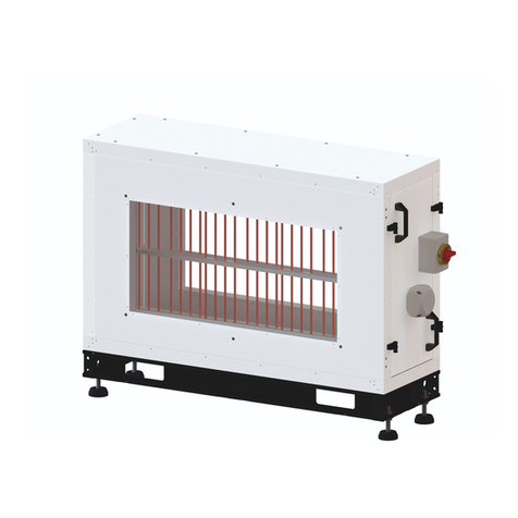
  9. Helios EHR-R TR Series Manual

Helios EHR-R TR Series Manual

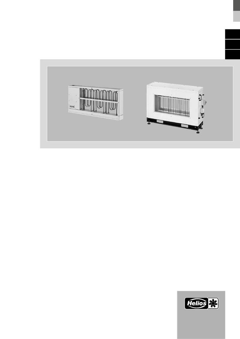
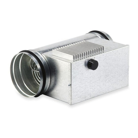
Elektro-Heizregister mit integrierter Heizungsregelung EHR-R.. TR
Electrical heating unit with integrated temperature controller EHR-R.. TR
Batterie électrique avec régulation du chauffage intégrée EHR-R.. TR
MONTAGE- UND BETRIEBSVORSCHRIFT
Zur Sicherstellung einer einwandfreien Funktion
und zur eigenen Sicherheit sind alle nachstehenden
Vorschriften genau durchzulesen und zu beachten.
Achtung: Alle Arbeiten sind im spannungslosen Zu-
stand vorzunehmen.
Sicherheitshinweis:
Die Steuerungselektronik inkl. Fühler und deren In-
stallation haben gegen Erde Netzpotential (230 V~).
Entsprechend ist die Installation, Wartung, Fehler-
suche usw. nach den geltenden Vorschriften der Netz-
spannungsinstallation nach VDE etc. durchzuführen.
EMPFANG
Sendung sofort bei Anlieferung auf Beschädigungen
und Typenrichtigkeit prüfen. Falls Schäden vorliegen,
umgehend eine Schadensmeldung unter Hinzuzie-
hung des Transportunternehmens veranlassen. Bei
nicht fristgerechter Reklamation, gehen evtl. Ansprü-
che verloren.
EINLAGERUNG
Der Lagerort muss erschütterungsfrei, wasserge-
schützt und frei von Temperaturschwankungen sein.
Schäden, deren Ursache in unsachgemäßem Trans-
port, Einlagerung oder Inbetriebnahme liegen, sind
nachweisbar und unterliegen nicht der Gewährlei-
stung.
EINSATZBEREICH
Die Elektro-Heizregister EHR-R.. TR mit integrier-
ter Heizungsregelung sind für den Einbau in den
Rohrverlauf von Lüftungssystemen konzipiert. Die
Geräte sind mit geschlossenen Rohrheizkörpern
(Stahlrohrmantelheizkörper mit niedriger Oberflä-
chentemperatur) ausgestattet, welche im außen-
lie
genden Anschlusskasten verdrahtet sind. Ein
Mindestvolumenstrom (siehe Tabelle) ist zu beachten.
Das Gehäuse ist aus verzinktem Stahlblech für den
Einbau in den Rohrverlauf.
MONTAGEHINWEISE
Das Heizregister ist in Strömungsrichtung nach dem
Ventilator in das Rohr einzubauen. Bei Einbau vor dem
Ventilator ist sicherzustellen, dass die Fördermitteltem-
peratur am Ventilator den maximal zulässigen Wert (sie-
he Katalog bzw. Typenschild) nicht übersteigt.
Zwischen Ventilator und Heizregister muss ein Rohr-
stück von mindestens 1 m Länge eingebaut sein. Es
ist gegebenenfalls durch geeignete Schutzeinrich-
tung sicherzustellen, dass ein Berühren der Heizstä-
be nicht möglich ist.
Auf ausreichende und sichere Befestigung ist zu
achten. Aus Sicherheitsgründen dürfen keine leicht
entzündlichen und brennbaren Materialien mit dem
Heizregister in Berührung kommen. Zu brennbaren
Materialien ist ein Mindestabstand von 150 mm ein-
zuhalten. Das ein- und austrittseitige Rohrstück muss
mindestens 0,5 m aus nichtbrennbarem Material be-
stehen. Um Heizstäbe vor Ablagerung von brennba-
ren Stäuben zu schützen, wird der Einbau von Luftfil-
tern (siehe Katalog: Type LFBR...) empfohlen.
Die Einbaulage ist beliebig, jedoch ist darauf zu achten,
dass sich der Temperaturbegrenzer oben befindet, da-
mit im Störungsfall die infolge Konvektion nach oben
fließende Wärme erfasst werden kann.
ANSCHLUSSHINWEISE
Der elektrische Anschluss darf nur von einer autori-
sierten Elektrofachkraft durchgeführt werden. Die ein-
schlägigen Sicherheitsvorschriften, Normen (wie VDE
0100, VDE 0530, VDE 0700, EN 60204-1 sowie die
TAB’s der EVU’s und UVV) sind einzuhalten.
Insbeson-
dere ist zu beachten, dass ein Betrieb des Heizregisters
nur bei eingeschaltetem Ventilator möglich sein darf.
Vor dem Anschluss ist zu prüfen, ob die auf dem
Typenschild angegebene Betriebsspannung mit der
Netzspannung übereinstimmt.
Der Betrieb ist bei 50 und 60 Hz Netzfrequenz mög-
FINTING AND OPERATING INSTRUCTIONS
To ensure trouble-free operation and for perso-
nal safety, all the following instructions should be
read carefully and observed.
Warning: All work must be carried out with the
equipment fully isolated from the power supply.
Safety information:
The control electronics incl. sensor and its installation
has mains potential (230 V) against earth. The installa-
tion, maintenance, troubleshooting, etc. is to be carri-
ed out in accordance with the applicable regulations of
the mains voltage installation according to VED, etc.
DELIVERY
On delivery, immediately check that the unit is un-
damaged and the correct model. In the event of
damage, make out an immediate damage report in
consultation with the carrier. A delay may render any
claim invalid.
STORAGE
The storage space must be vibration-free, protected
from damp and from fluctuations in temperature. Any
damage found to be due to inappropriate transpor-
tation, storage or operation falls outside the terms of
the guarantee.
INSTALLATION
EHR-R.. TR electrical heating units are designed to
be fitted into the ducting of ventilation systems. The
units have closed pipe-elements (low surface tempe-
rature elements with steel casing). The minimum air
volume through the unit must be complied with (see
table). Built in thermal cut outs are fitted to the ca-
sing. The unit casing is of galvanised sheet steel with
spigots for installation in to ducting.
INSTALLATION INSTRUCTIONS
The heater unit should be installed in the ducting
downstream of the fan. In the case of installation
upstream of the fan, ensure that the airflow-tem-
perature at the fan does not exceed the maximum
permitted value (see catalogue or name plate rating).
A minimum of 1 metre of ducting must be installed
between the fan and the heater unit. Always ensure
measures are to be taken so that it is not possible to
touch the heating elements.
The heater must be securely fixed in position. For
safety, no inflammable materials must come into
contact with the heater unit. There must be kept at
a minimum clearance distance of 150mm between
the heater unit and any inflammable material. The
ducting immediately upstream and downstream of
the unit must be of non-inflammable material for a
distance of 0.5m. In order to protect the heating ele-
ments from a build up of inflammable dust, the ins-
tallation of air filters is recommended (see catalogue:
type LFBR).
The unit may be mounted at any angle, however it is
recommended that the unit is horizontal and the ther-
mal cut-outs are uppermost. This position ensures
the correct operation of the thermal cut-outs.
CONNECTION INSTRUCTIONS
Electrical connection is to be carried out only by a
qualified electrician, observing the appropriate regu-
lations and guidelines of national bodies (VDE, OVE,
SEV IEE etc) and the EVU (e.g. VDE 0100/DIN57100
T.420) VDE0721, DIN18379).
Special attention is to be drawn to the need to en-
sure that operation of the heater unit is only possible
when the fan is switched on, and that the applian-
ce is automatically and completely isolated from the
mains if the thermal cut-out or safety thermal cut-out
is triggered.
Before connection to the mains, ensure that the ope-
NOTICE DE MONTAGE ET D‘UTILISATION
Il est important de lire et de respecter l‘ensemble
des prescriptions suivante, pour le bon fonctionne-
ment de l‘appareil et la sécurité des utilisateurs.
Attention: Tous les travaux doivent être éffectués
hors tension.
Consignes de sécurité :
La commande électronique, sondes incluses, et, l’in-
stallation ont une tension réseau à la terre (230 V~).
Respecter les normes de l’installation réseau selon
VDE, etc. lors de l’installation, l’entretien, la recherche
de défauts, etc.
RECEPTION
Dès réception, vérifier l‘état et la conformité du
matériel commandé. En cas d‘avaries, des réserves
doivent être portées sur le bordereau du transpor-
teur. Elles doivent être précises, significatives, com-
plètes et confirmées dans les 3 jours par lettre re-
commandée. Attention le non respect du délai peut
entraîner le rejet de la réclamation.
STOCKAGE
Le matériel est à stocker dans un endroit abrité de
l‘eau, exempt de variations de température et de vibra-
tions. Les dommages dus à de mauvaises conditions
de transport, à des stockages défectueux ou à une uti-
lisation anormale sont sujets à vérification et contrôle
et entraînent la suppression de notre garantie.
DOMAINE D‘UTILISATION
Les batteries de chauffe électrique EHR-R.. TR sont
prévues pour un montage en gaines rondes. Ces
appareils sont équipés de résistances à tubes ayant
une faible température de surface, reliés à un boîtier
de raccordement extérieur. Attention : respecter un
débit d‘air minimum (voir tableau). Thermostat de sé-
curité double étage intégré.
Le caisson est en tôle d‘acier galvanisée pour un
montage en gaine ronde.
MONTAGE
La batterie doit être montée APRES le ventilateur. En
cas de montage AVANT le ventilateur, s‘assurer que
la température du flux ne dépasse pas celle autorisée
pour le ventilateur (voir catalogue ou plaque signalé-
tique). Intercaler entre le ventilateur et la batterie une
longueur de gaine d‘au moins 1 mètre. S‘assurer que
des mesures de sécurité appropriées sont en place
afin d‘éviter tout contact avec les éléments chauffants.
Vérifier que la fixation est suffisante. Par mesure de
sécurité, veiller à ce qu‘aucun matériau inflammable
ne puisse entrer en contact avec la batterie. Re-
specter une distance de 15 cm avec toute matière
inflammable. La section de gaine à l‘aspiration et au
refoulement sur minimum 50 cm doit être en matière
non inflammable pour protéger les résistances du
dépôt de matière inflammable (l‘utilisation de filtres
(type LFBR…, voir catalogue) est recommandée).
La batterie peut être montée dans n‘importe quelle
position. Veiller seulement à ce que le thermostat se
trouve en haut afin qu‘ en cas de panne la convection
de chaleur puisse être enregistrée.
BRANCHEMENT ELECTRIQUE
Le branchement électrique doit être effectué par un
électricien qualifié. Les consignes de sécurité et les
règles d‘installation en vigueur (VDE OVE SEV ainsi
que EVU par ex. VDE 0100/DIN 57100, T. 420, VDE
0721, DIN 18379) doivent être respectées.
Il faut en particulier veiller à ce que la batterie ne pu-
isse s‘enclencher que si le ventilateur est en foncti-
onnement et que le déclenchement du thermostat de
sécurité double étage coupe l‘alimentation électrique
de toutes les phases de la batterie. L‘enclenchement
doit être manuel. Un branchement adéquat permet
un fonctionnement par groupes et de ce fait une ré-
duction de la puissance de chauffe.
Le fonctionnement est possible en 50 et 60 Hz. Voir
Elektro-Heizregister mit integrierter Heizungsregelung EHR-R.. TR
Electrical heating unit with integrated temperature controller EHR-R.. TR
Batterie électrique avec régulation du chauffage intégrée EHR-R.. TR
lich. Die Einsatzmöglichkeiten der Typen sind aus
dem jeweiligen Anschlussplan zu entnehmen.
Bei dem elektrischen Anschluss beachten Sie unbe-
dingt die Angaben auf dem dargestellten Schaltsche-
ma. Auf ausreichende Leiterquerschnitte ist zu achten!
FUNKTION
Die Elektro-Heizregister EHR-R.. TR sind zur Erwär-
mung der Zuluft in einer Lüftungsanlage bestimmt.
Durch Anschluss eines Kanalfühlers TFK, bzw. Raum-
fühlers TFR (zwingend notwendiges Zubehör) ist eine
konstante Zulufttemperatur- oder Raumtemperaturre-
gelung möglich. Abhängig von Soll- und Istwert regelt
das EHR-R.. TR automatisch die Stromzufuhr und da-
mit die erforderliche Heizleistung bis hin zur maximalen
Heizleistung. Bei Auslösen der Sicherheits-Tempera-
turbegrenzer schaltet die Regeleinheit ab.
BETRIEB UND WARTUNG
Die angegebene Mindestluftmenge darf nicht unter-
schritten werden, da sonst mit einem Auslösen des
Temperaturbegrenzers zu rechnen ist.
Die Heizregister erzeugen einen zusätzlichen Druck-
verlust, der bei Dimensionierung der Gesamtanlage
zu berücksichtigen ist. Die Temperaturerhöhung des
Fördermittels ist abhängig von Volumenstrom und
Heizleistung (Werte siehe Diagramme).
Weiterhin sind die einschlägigen Bestimmungen für
den Betrieb von Elektro-Lufterhitzern zu beachten. Je
nach Verschmutzungsgrad der geförderten Luft sind
die Heizstäbe von Zeit zu Zeit auf Anbackungen zu
überprüfen und ggfs. zu reinigen. Das geförderte Me-
dium darf keine brennbaren oder leicht entzündlichen
Bestandteile enthalten.
Achtung: Die Geräte besitzen keinen Ex-Schutz. Auf
die einschlägigen Ex-Schutz-Bestimmungen wird
hingewiesen. Es ist zu beachten, dass das Gerät vor
dem Öffnen des Anschlusskastens allpolig vom Netz
getrennt wird und spannungsfrei ist.
FI-Schutzschalter
Ist die Installation von einem FI-Schutzschalter ge-
schützt und dieser bei Anschluss des Gerätes aus-
löst, kann dies an Feuchtigkeit im Heizkörper liegen.
Wenn ein Gerät, das einen Heizkörper hat, längere
Zeit nicht benutzt oder in feuchter Umgebung gela-
gert worden ist, kann Feuchtigkeit eindringen. Dies
ist nicht als Fehler anzusehen, doch sollte eine Über-
prüfung einer Elektrofachkraft erfolgen, um auszu-
schließen, ob evtl. doch eine andere Störung vorliegt.
Wenn dies zutrifft, darf das Gerät nicht weiterbetrie-
ben werden. Liegt keine zusätzliche Störung vor, ist
es am einfachsten, das Gerät an eine Steckdose oh-
ne FI-Schutzschalter anzuschließen, wobei der Heiz-
körper trocknet. Die Trockenzeit kann von 1 Stunde
bis zu einigen Tagen dauern. Vorbeugenderweise
sollte die Anlage bei längerem Stillstand kurze Zeit in
Betrieb genommen werden.
ZUBEHÖR
Der Gebrauch von Zubehörteilen, die nicht von Helios
empfohlen oder angeboten werden, ist nicht statthaft.
Eventuell auftretende Schäden unterliegen nicht der
Gewährleistung.
Systemzubehör:
Kanalfühler TFK (Best.-Nr. 5005)
Raumfühler TFR (Best.-Nr. 5006)
GARANTIEANSPRÜCHE – HAFTUNGSAUS-
SCHLUSS
Wenn die vorausgehenden Ausführungen nicht be-
achtet werden, entfällt unsere Gewährleistung und
Behandlung auf Kulanz. Gleiches gilt für abgeleitete
Haftungsansprüche an den Hersteller.
VORSCHRIFTEN – RICHTLINIEN
Bei ordnungsgemäßer Installation und bestimmungs-
gemäßem Betrieb entspricht das Gerät den zum
Zeitpunkt seiner Herstellung gültigen Vorschriften,
Richtlinien.
rating voltage shown on the name plate complies wi-
th the mains voltage. Operation is possible at 50 Hz
and 60 Hz mains supply.
The unit is to be connected only as detailed is wiring
diagram SS 476.2 with cables of adequate capacity!
FUNCTION
The electric heater batteries EHR-R.. TR are desi-
gned to heat up the supply air in a ventilation system.
A constant supply air- or room temperature may be
achieved using a duct sensor TFK or room sensor
TFR (mandatory accessory). Depending on set point
and actual value the EHR-R..TR automatically regula-
tes the current and consequently the heating power
up to the maximum load. In case of overheating the
safety thermostat switches the unit off.
OPERATION AND MAINTENANCE
The minimum airflow values shown in the table must
be maintained, otherwise the thermal cut-out will
be triggered. Heater units generate an additional
resistance in air pressure and this should be taken
in to account when planning the dimensions of the
entire system. The air temperature increase depends
on the airflow volume and heat output (for values see
diagram). Local regulations for the operation of elec-
trical air heaters must be complied with. Depending
on the particular airflow and contamination levels, the
heating elements must be periodically examined for
baked on deposits and if necessary cleaned. The
airflow must contain no inflammable or flammable
substances.
Attention: the units possess no explosion proof ra-
ting or protection. Please refer to the appropriate re-
gulations for to ensure that this unit is safe to use with
specific air borne contamination. Isolate the unit from
the mains before opening the terminal box.
Earth leakage circuit breaker
If the installation is protected by an earth leakage
circuit breaker that is activated when switching on
the unit, it may be damp in the heating element. If
a unit with a heating element remains unused over a
long period, or has been stored in a damp environ-
ment, it may be penetrated by damp. This is not to
be regarded as a fault. However, a qualified electrici-
an should carry out an inspection in order to ensure
that no other fault is present. If no additional fault is
present, the simplest solution is to connect the unit to
without an earth leakage circuit breaker, to allow it to
dry out. The drying time required may range from 1
hour to several days. In order to prevent the situation
from reoccurring when the unit is to remain idle for a
protracted period, it should occasionally be switched
on for a short time.
ACCESSORIES
The use of accessories not recommended or pro-
vided by HELIOS is not permitted. Damage arising
from such usage is not covered by the guarantee.
System Accessories:
Duct sensor TFK (order no. 5005)
Room sensor TFR (order no. 5006)
GUARANTEE CLAIMS – EXCLUSION OF
LIABILITY
If the above instructions are not observed, you will in-
validate our guarantee. The manufacturer is not liable
for misuse of this unit..
REGULATIONS – GUIDELINES
When properly installed and operated the appliance
conforms to the regulations and guidelines applying
at time of manufacture.
les différentes possibilités d‘installation sur le schéma
de principe SS 476.2. Lors du branchement élec-
trique, respecter impérativement les caractéristiques
données sur le schéma de branchement.
Veiller à laisser une section de câble suffisante.
FONCTION
La batterie électrique EHR-R.. TR permet de réchauf-
fer la température de soufflage dans les réseaux
aérauliques. En raccordant une sonde de gaine TFK,
ou une sonde d’ambiance TFR (accessoires néces-
saires), il est possible d’obtenir une température
de soufflage ou d’ambiance constante. La batterie
EHR-R.. TR régule automatiquement son alimen-
tation électrique et ainsi la puissance de chauffe
nécessaire (jusqu’à atteindre la puissance maximum)
en fonction de la température de consigne et de la
température réelle. La régulation est coupée si le
thermostat de sécurité se déclenche.
FONCTIONNEMENT ET ENTRETIEN
Le débit d‘air minimum ne doit pas être inférieur à
la valeur indiquée (voir tableau), au risque de voir le
thermostat de sécurité se déclencher. Les batteries
provoquent une perte de charge supplémentaire
dont il faut tenir compte lors de l‘étude de l‘ensemble
de l‘installation.
L‘augmentation de la température du flux dépend du
débit et de la puissance de chauffe (cf diagramme).
Respecter les règles de l‘art pour l‘utilisation des
batteries de chauffe électriques. Selon le degré de
pollution de l‘air, les résistances chauffantes sont à
vérifier périodiquement et au cas échéant à nettoyer.
Le fluide véhiculé ne doit pas contenir de particule
inflammable.
Attention: ces appareils ne possèdent pas de pro-
tection Ex. Tenir compte des dispositions de protec-
tion antidéflagrantes contractuelles. Veiller à ce que
l‘appareil soit hors tension avant l‘ouverture du boîtier
de raccordement.
Disjoncteur
Si l‘installation est protégée par un disjoncteur et que
celui-ci déclenche à la mise en service de la batterie,
il est probable que la cause soit une humidité import-
ante des résistances. Lorsque la batterie n‘est pas
utilisée pendant une longue période ou stockée dans
un endroit humide, il est possible que l‘humidité s‘in-
troduise dans les éléments chauffants.
Ceci ne doit pas être considéré comme un défaut du
matériel. Néanmoins il est conseillé de faire vérifier
la batterie de chauffe par un électricien pour exclure
toute autre cause de panne. En l‘absence d‘autre dé-
faut, il est conseillé de sécher la batterie en la bran-
chant simplement sur une alimentation non protégée
par disjoncteur.
La durée du séchage peut varier d‘une heure à plu-
sieurs jours. Nous conseillons de faire fonctionner
l‘installation périodiquement afin d‘éviter de longues
périodes d‘arrêt propices à ce genre de problèmes.
ACCESSOIRES
L‘utilisation d‘accessoires et d‘équipements qui ne
sont pas directement fournis ou conseillés par Helios
n´est pas autorisée. Nous déclinons toute respons-
abilité en cas de défaut consécutif à leur utilisation.
Accessoires :
Sonde de gaine TFK (N° Réf. 5005) accessoire
Sonde d‘ambiance TFR (N° Réf. 5006) accessoire
DEMANDE DE GARANTIE – RESERVES DU
CONSTRUCTEUR
En cas de non-respect des indications précédentes,
toute demande de remplacement ou de réparation
à titre gratuit sera déclinée. Il en sera de même pour
toute implication de responsabilité du fabricant.
REGLEMENTATIONS – NORMES
Cet appareil est conforme aux directives CE en vi-
gueur le jour de sa fabrication sous réserve d‘une
utilisation appropriée.
Elektro-Heizregister mit integrierter Heizungsregelung EHR-R.. TR
Electrical heating unit with integrated temperature controller EHR-R.. TR
Batterie électrique avec régulation du chauffage intégrée EHR-R.. TR
E - Heizungs Element / heating elements / élément blindé
F1 - Sicherheitsthermostat 1 / safety thermostat 1 / thermostat de sécurité 1
F2 - Sicherheitsthermostat 2 / safety thermostat 2 / thermostat de sécurité 2
N - Pulser Elektronik / Pulse single-phase output controller / régulateur triac
1
2
3
4Eingang Fühler
-entrée sonde
Eingang externe Sollwertvorgabe
-entrée consigne externe
Potentiometer interne Sollwertvorgabe
-potentiomètre de consigne intégré
Brücke für Auswahl Schaltungsart
- cavalier de sélection du mode fonctionnement
N
L Eingang
- entrée
L Ausgang
- sortie
1234
Potentiometer
interne
Sollwertvorgabe
- potentiomètre
de consigne intégré
TFK
1234
TFK
Mit TFK-Kanalfühler,
Sollwert intern
- avec sonde de gaine TFK, consigne interne
1
2
3
4
TFR
Mit TFK-Kanalfühler,
Sollwert extern mit TFR
- avec sonde de gaine TFK
- consigne externe avec TFR
Raumfühler und
Sollwert extern mit TFR
- sonde d'ambiance et consigne
externe avec TFR
1234
1
2
3
4
TFR
92879 002 SS-799,1 27.02.13
EHR-R ../... TR, 1~ Type
Heizregister / electric heater battery / batterie de chauffage électrique
F1 F2
21
N
PE
E
NL
Temperaturbegrenzer
Thermal cutout
Limiteur de température
PE
MANUAL
AUTO
RESET
Heizstäbe
1 x 0,8kW / 230V
2,4/160 2 x 1,2kW / 230V
/ Heating coils / Résistances de chauffage
EHR-R ../... TR
0,8/125
230V~
SS-799.1
E - Heizungs Element / heating elements
F1 - Sicherheitsthermostat 1 / safety thermostat 1
F2 - Sicherheitsthermostat 2 / safety thermostat 2
N- Pulser Elektronik / Pulse single-phase output controller
K - Relais / relay / relais
/ élément blindé
/ thermostat de sécurité 1
/ thermostat de sécurité 2
/ régulateur triac
L2
1234
TFK
1234
TFK
1
2
3
4
TFR
1234
1
2
3
4
TFR
92880 002 SS-800,1 28.02.13
Temperaturbegrenzer
Thermal cutout
Limiteur de température
L1
1
N
F1 F2
2
N
3
L2
PE
KE
PE
MANUAL
AUTO
RESET
EHR-R ../... TR, 2~ Type
Heizregister / electric heater battery / batterie de chauffage électrique
400V~
Heizstäbe
EHR-R ../... TR
5/200 2 x 2,5kW / 400V
6/250 2 x 3,0kW / 400V
6/315 2 x 3,0kW / 400V
/ Heating coils / Résistances de chauffage
1
2
3
4Eingang Fühler
-entrée sonde
Eingang externe Sollwertvorgabe
-entrée consigne externe
Potentiometer interne Sollwertvorgabe
-potentiomètre de consigne intégré
Brücke für Auswahl Schaltungsart
- cavalier de sélection du mode fonctionnement
L Eingang
- entrée
L Ausgang
- sortie
Mit TFK-Kanalfühler,
Sollwert intern
- avec sonde de gaine TFK, consigne interne
Mit TFK-Kanalfühler,
Sollwert extern mit TFR
- avec sonde de gaine TFK
- consigne externe avec TFR
Raumfühler und
Sollwert extern mit TFR
- sonde d'ambiance et consigne
externe avec TFR
Potentiometer
interne
Sollwertvorgabe
- potentiomètre
de consigne intégré
SS-800.1
Elektro-Heizregister mit integrierter Heizungsregelung EHR-R.. TR
Electrical heating unit with integrated temperature controller EHR-R.. TR
Batterie électrique avec régulation du chauffage intégrée EHR-R.. TR
Elektro-Heizregister mit integrierter Heizungsregelung EHR-R.. TR
Electrical heating unit with integrated temperature controller EHR-R.. TR
Batterie électrique avec régulation du chauffage intégrée EHR-R.. TR
F1 F2
K
N
E
N
1
MANUAL
AUTO
RESET
L1
2
L3L2
34 PE
E - Heizungs Element
F1 - Sicherheitsthermostat 1
F2 - Sicherheitsthermostat 2
N - Pulser Elektronik
K - Relais
/ heating elements
/ safety thermostat 1
/ safety thermostat 2
/ Pulse single-phase output controller
/ relay
/ élément blindé
/ thermostat de sécurité 1
/ thermostat de sécurité 2
/ régulateur triac
/ relais
Temperaturbegrenzer
Thermal cutout
Limiteur de température
1
Potentiometer bei interner
Sollwertvorgabe
- Potentiomètre de
consigne intégré
92881 002 SS-801,1 04.03.13
PE
2 3 4 5 6 7 8
MIN/MAX Betriebsart / mode de
fonctionnement
TFK
Mit TFK-Kanalfühler TFR-Raumfühler, Sollwertoder intern.
- avec sonde de gaine TFK ou sonde d'ambiance TFR, consigne interne
1
2
3
4
TFR
TFK
1
2
3
4
TFR
Mit TFK-Kanalfühler TFR-Raumfühler,
Sollwert
und
intern und Betrieb.MIN / MAX
- Avec sonde de gaine TFK et sonde d'ambiance
TFR, consigne interne et fonctionnement MIN/MAX
MIN / MAX
Minimum / Maximum
Überwachung inaktiv
- contrôle inactif
Minimum
Überwachung aktiv
- contrôle actif
Maximum
Überwachung aktiv
- contrôle actif
Minimum / Maximum
Überwachung aktiv
- contrôle actif
Mit TFK-Kanalfühler TFR-Raumfühler,
Sollwert
und
extern und Betrieb.MIN / MAX
- Avec sonde de gaine TFK et sonde d'ambiance
TFR, consigne externe et fonctionnement MIN/MAX
Mit TFR-Raumfühler, Sollwert extern.
- avec sonde d'ambiance TFR, consigne externe
30 50
40
MAX 515
10
MIN
oder
ou
14
MIN/MAX
Betriebsart / mode de
fonctionnement
Minimum / Maximum
Überwachung inaktiv
- contrôle inactif
1 2 3 4 5 6 7 8
Betriebsart
/ mode de
fonction-
nement
TFK
1
2
3
4
TFR
1 2 3 4 5 6 7 8
Minimum / Maximum
Überwachung aktiv
- contrôle actif
MIN/MAX
1 2 3 4 5 6 7 8
1
2
3
4
TFR
Mit TFK-Kanalfühler./
TFR-Raumfühler als Sollwertsteller
Avec sonde d'ambiance TFK.
- Sonde d'ambiance TFR pour consigne externe
extern.
MIN/MAX
Betriebsart / mode de
fonctionnement
Minimum / Maximum
Überwachung inaktiv
- contrôle inactif
TFK
1
2
3
4
TFR
1 2 3 4 5 6 7 8
Betriebsart
/ mode de
fonction-
nement
Minimum / Maximum
Überwachung aktiv
- contrôle actif
MIN/MAX
1
2 3
4 5
EHR-R ../... TR, 3~ Type
Heizregister / electric heater battery / batterie de chauffage électrique
Heizstäbe
EHR-R ../... TR
9/355 3 x 3,0kW / 400V
12/355 4 x 3,0kW / 400V
9/400 3 x 3,0kW / 400V
/ Heating coils / Résistances de chauffage
400V~
SS-801.1
Druckschrift-Nr. 91 731-001/ 07.17
Elektro-Heizregister mit integrierter Heizungsregelung EHR-R.. TR
Electrical heating unit with integrated temperature controller EHR-R.. TR
Batterie électrique avec régulation du chauffage intégrée EHR-R.. TR
Type Best.Nr. Leistung Schaltgruppen- Strom- Mindest- passend zu Anschluss Abmessungen Gewicht
Anz. Aufnahme volumenstrom Ventilator Schaltplan ca.
Type Order No. Output Switchable Elements Amperage Min Airflow Suit Fan Ventilator Connect. Diag No Dimensions Weight
Type N° Réf. Puissance Nombre de groupes Courant absorbé Débit mini.
pour ventilateur de
N° de branchement Dimensions Poids
Ø en mm
Ø D H L
kW x kW A m3/h NG mm Nr. mm mm mm kg
Einphasen-Wechselstrom 1~, 230 V / 1 Phase 230 V, 1ph / Monophasé 230 V
EHR-R 0,8/125 TR 5293 0,8 1 x 0,8 3,5 43 125 799.1 125 225 325 2,2
EHR-R 2,4/160 TR 5249 2,4 2 x 1,2 10,4 129 160 799.1 160 260 380 3,1
Zweiphasen-Wechselstrom 2~, 400 V / 2 Phase 400 V, 2 ph / Biphasé 400 V
EHR-R 5/200 TR 5295 5,0 1 x 2 x 2,5 12,5 268 200 800.1 200 300 380 3,5
EHR-R 6/250 TR 5296 6,0 1 x 2 x 3,0 15,0 321 250 800.1 250 350 380 5,7
EHR-R 6/315 TR 5301 6,0 1 x 2 x 3,0 15,0 321 315 800.1 315 415 380 6,4
Drehstrom 3~, 400 V / 3 Phase 400 V, 3 ph / Triphasé 3~, 400 V
EHR-R 9/355 TR 5297 9,0 1 x 3 x 3,0 13,0 482 355 801.1 355 455 380 9,5
EHR-R 12/355 TR 5298 12,0 1 x 4 x 3,0 20,0 803 355 801.1 355 455 495 10,5
EHR-R 9/400 TR 5299 9,0 1 x 3 x 3,0 13,0 482 400 801.1 400 500 380 8,9
Maße in mm siehe Tabelle
Dimensions in mm, see table
Dimensions en mm, voir tableau
Service und Information
DHELIOS Ventilatoren GmbH & Co · Lupfenstraße 8 · 78056 VS-Schwenningen FHELIOS Ventilateurs · Z.I. La Fosse à la Barbière · 2, rue Louis Saillant · 93605 Aulnay sous Bois Cedex
CH HELIOS Ventilatoren AG · Tannstraße 4 · 8112 Otelfingen GB HELIOS Ventilation Systems Ltd. · 5 Crown Gate · Wyncolls Road · Severalls Industrial Park ·
AHELIOS Ventilatoren · Postfach 854 · Siemensstraße 15 · 6023 Innsbruck Colchester · Essex · CO4 9HZ
Temperatur-Erhöhung K p=1,20 kg/m3
temperature increase /
Elévations de temperature en °K
9 kW
5,0
K
D T
0,8 6,0
V
.m3/h
2,4
4
5
3
2
1
1 EHR-R 0,8/125 TR
2 EHR-R 2,4/160 TR
3 EHR-R 5/200 TR
4 EHR-R 6/250 TR
5 EHR-R 6/315 TR
6 EHR-R 9/355 TR
7 EHR-R 12/355 TR
8 EHR-R 9/400 TR
68
Druckverlust / pressure loss p=1,20 kg/m3
Perte de pression
Dp
Pa
V
.m3/h
7
F3
123
L
S2
S3
K1
K2
K2
K1K1
K1
N
K2
S4
K3T
K1
K4
K3T
Nachlauf
60 sec.
45
A1 BA1A1A1
K4
K4K2
3 - Lüfter Ein
- Fan
- Ventilateur
4 - Heizung Ein
- Heater
- Chauffage
5 - Störung
- Warning light
- Dérangement
S1 - Hauptschalter
- Main switch
- Interrupteur principal
F1 - Temperaturbegrenzer
- Thermal cutout
- Limiteur de température
F2 - Temperaturwächter
- Temperature sensor
- Contrôleur de température
F3 - Strömungswächter
- Air flow switch
- Contrôle de flux d'air
F4 - Thermo Kontakt Motor
- Thermal contact motor
- Thermocontacts moteur
S2 - Anlage Aus
- System OFF
- Arrêt système
S3 - Lüftung Ein
- Fan ON
- Marche ventilateur
S4 - Heizung Ein
- Heater ON
- Marche chauffage
1 - Steuerung Ein
2 - Generierung Nachlaufzeit Lüfter
F4
TK
PE PE
EHR-R ./... TR
1~ Type SS-799,1
2~ Type SS-800,1
3~ Type SS-801,1
Fühlerkombinationen
L / N / PE
Überhitzungs-
thermostate intern !
1~ Type:
2~ Type:
3~ Type:
N/L1/L2/PE
N/L1/L2/L3/PE
Minimal Steuerung (Prinzip)
Basic circuit requirements
Principe contrôle min.
Bauseits zu erstellen /
To be supplied by others /
Furnitures et réalisation par installateur
Zuleitung / Supply / Fil d'amenée
Strömungswächter
Air flow switch
Contrôle de flux d'air
1 / 3 ~Ph
Ventilator / Fan /
Ventilateur
+ TK
F1
F2
92958 001 SS-842 30.08.04
F3
F4
SS-842

Other manuals for EHR-R TR Series

2

This manual suits for next models

16

Other Helios Heater manuals

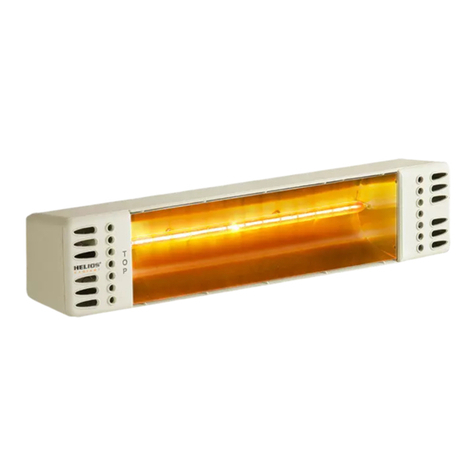
Helios TOP IRK User manual

Helios

Helios TOP IRK User manual

Helios 400C User manual

Helios

Helios 400C User manual

Helios easyControls 3.0 User manual

Helios

Helios easyControls 3.0 User manual

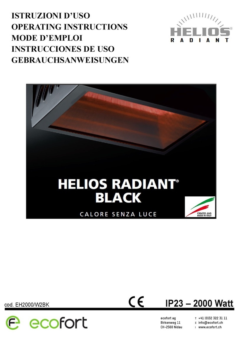
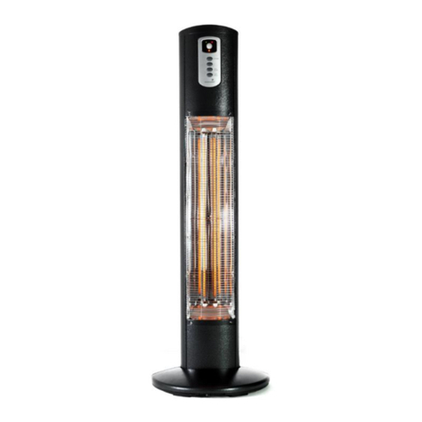
Helios Radiant Black EH2000/W2BK User manual

Helios

Helios Radiant Black EH2000/W2BK User manual

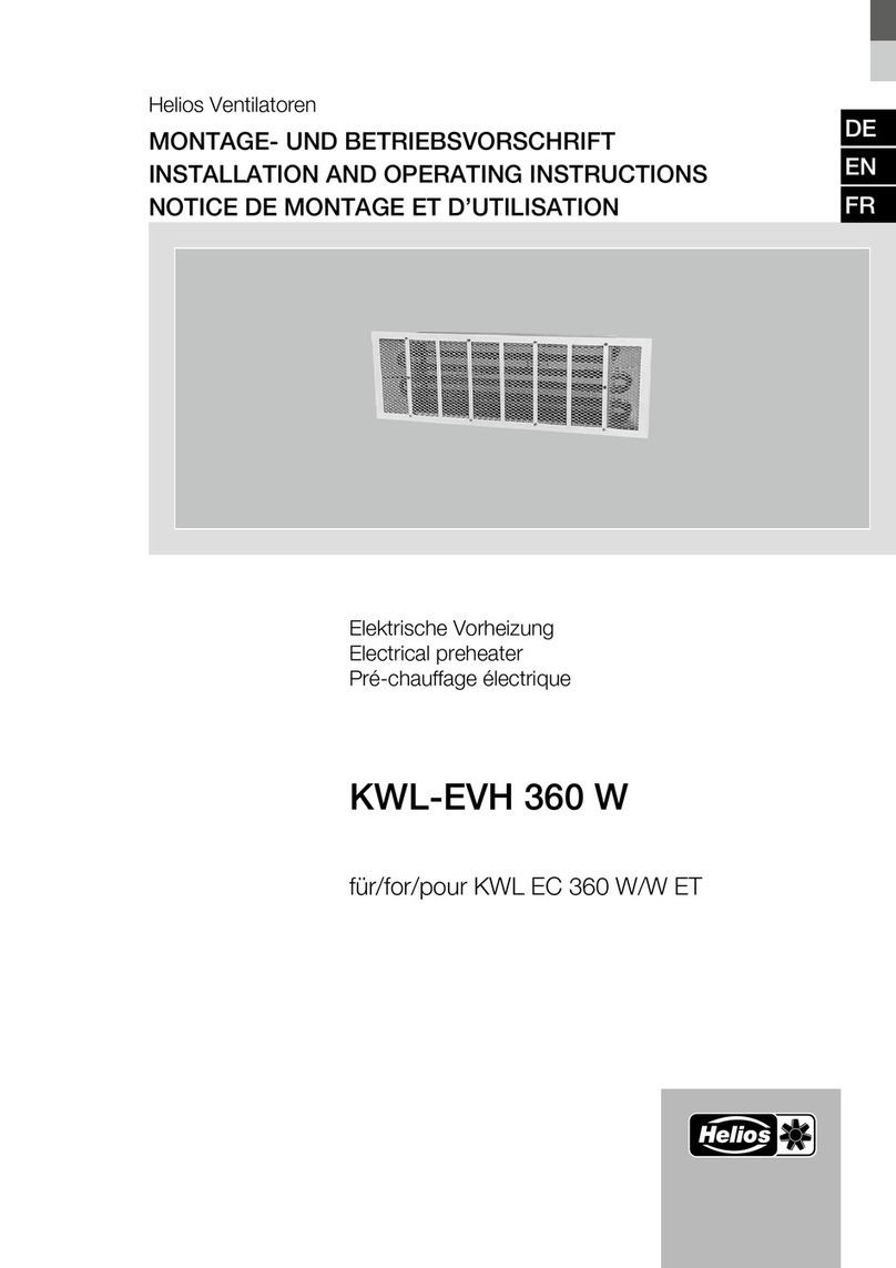
Helios KWL-EVH 200 W User manual

Helios

Helios KWL-EVH 200 W User manual

Helios EHR-R TR Series Manual

Helios

Helios EHR-R TR Series Manual

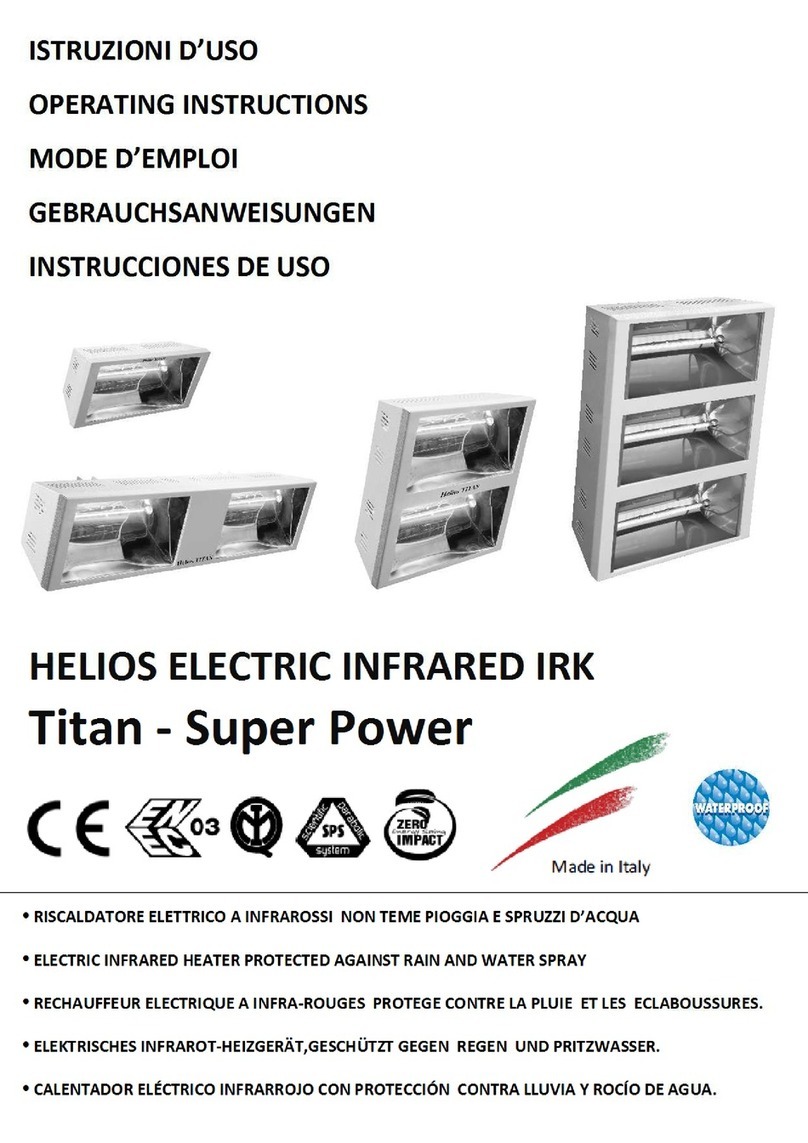
Helios Titan Series User manual

Helios

Helios Titan Series User manual

Helios SH Series User manual

Helios

Helios SH Series User manual

Helios KWL-EVH 500 W User manual

Helios

Helios KWL-EVH 500 W User manual

Helios STH 3 User manual

Helios

Helios STH 3 User manual

Helios HP1/10 User manual

Helios

Helios HP1/10 User manual

Helios KWL-EVH 360 W User manual

Helios

Helios KWL-EVH 360 W User manual

Helios EPH2960 User manual

Helios

Helios EPH2960 User manual

Helios AIR1-EVH RH User manual

Helios

Helios AIR1-EVH RH User manual

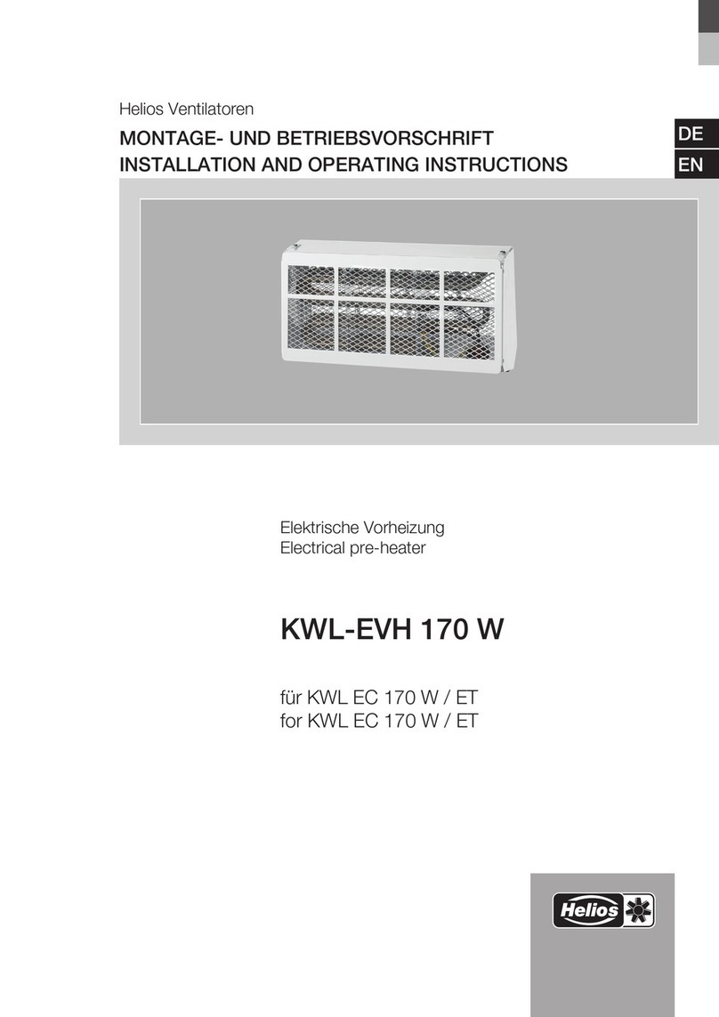
Helios KWL-EVH 170 W User manual

Helios

Helios KWL-EVH 170 W User manual

Helios KWL-EVH 470 W User manual

Helios

Helios KWL-EVH 470 W User manual

Helios AIR1-ENH User manual

Helios

Helios AIR1-ENH User manual

Helios AIR1-AAHK User manual

Helios

Helios AIR1-AAHK User manual

Popular Heater manuals by other brands

HeatStar THP750S user manual

HeatStar

HeatStar THP750S user manual

Reznor UEZ manual

Reznor

Reznor UEZ manual

Broan 170F Finish assemblies

Broan

Broan 170F Finish assemblies

CLIMASTAR OPTIMUS user guide

CLIMASTAR

CLIMASTAR OPTIMUS user guide

Melchioni GOBI user manual

Melchioni

Melchioni GOBI user manual

Klarstein 10032003 manual

Klarstein

Klarstein 10032003 manual

cecotec READYWARM 2000 MAX CERAMIC ROTATE DESIGN instruction manual

cecotec

cecotec READYWARM 2000 MAX CERAMIC ROTATE DESIGN instruction manual

Consort FANFAIR PFH15T manual

Consort

Consort FANFAIR PFH15T manual

Wilfa Lun Komfort POB-600 instruction manual

Wilfa

Wilfa Lun Komfort POB-600 instruction manual

Black & Decker BHRO608 instruction manual

Black & Decker

Black & Decker BHRO608 instruction manual

CLIMASTAR SMART TOUCH 500 Installation manual and user's guide

CLIMASTAR

CLIMASTAR SMART TOUCH 500 Installation manual and user's guide

AUROOM Aura 4,5 kW Installation and instruction manual

AUROOM

AUROOM Aura 4,5 kW Installation and instruction manual

Pelonis HF-0063 user manual

Pelonis

Pelonis HF-0063 user manual

EUROM EK5001 operating instructions

EUROM

EUROM EK5001 operating instructions

SEELEY INTERNATIONAL Braemar Invertair SACV10D1S installation manual

SEELEY INTERNATIONAL

SEELEY INTERNATIONAL Braemar Invertair SACV10D1S installation manual

Hyundai HAL 100 instruction manual

Hyundai

Hyundai HAL 100 instruction manual

Vitek VT-1703 Manual instruction

Vitek

Vitek VT-1703 Manual instruction

CTB Chore-Time QuadRadiant Operator's manual

CTB

CTB Chore-Time QuadRadiant Operator's manual

manuals.online logo
manuals.online logoBrands
  • About & Mission
  • Contact us
  • Privacy Policy
  • Terms and Conditions

Copyright 2025 Manuals.Online. All Rights Reserved.