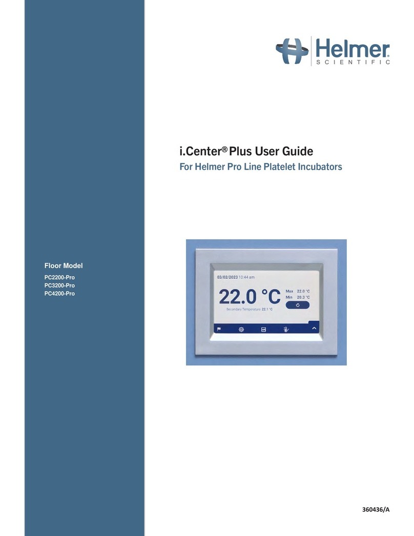
Helmer PC2200-Pro Manual

360432/A
Platelet Incubator Instructions for Use Manual
Pro Line Floor Model Incubator with i.Center®Plus
Floor Model
PC2200-Pro
PC3200-Pro
PC4200-Pro

Document Updates
The document is furnished for information use only, is subject to change without notice and should not be construed as a commitment
by Helmer Scientic. Helmer Scientic assumes no responsibility or liability for any errors or inaccuracies that may appear in the
informational content contained in this material. For the purpose of clarity, Helmer Scientic considers only the most recent revision of
this document to be valid.
Notices and Disclaimers
Condential / Proprietary Notices
Use of any portion(s) of this document to copy, translate, disassemble or decompile, or create or attempt to create by reverse
engineering or otherwise replicate the information from Helmer Scientic products is expressly prohibited.
Copyright and Trademark
Helmer®, i.Center®, AgiTrak™, and Rel.i™ are registered trademarks or trademarks of Helmer, Inc. in the United States of America.
Copyright © 2023 Helmer, Inc. All other trademarks and registered trademarks are the property of their respective owners.
Helmer, Inc., doing business as (DBA) Helmer Scientic and Helmer.
Disclaimer
This manual is intended as a guide to provide the operator with necessary instructions on the proper use and maintenance of certain
Helmer Scientic products.
Any failure to follow the instructions as described could result in impaired product function, injury to the operator or others, or void
applicable product warranties. Helmer Scientic accepts no responsibility for liability resulting from improper use or maintenance of
its products.
The screenshots and component images appearing in this guide are provided for illustrative purposes only, and may vary slightly from
the actual software screens and/or product components.
Helmer Scientic
14400 Bergen Boulevard
Noblesville, IN 46060 USA
www.helmerinc.com
Part No. 360432/ Rev A
Document History
Revision Date CO Supersession Revision Description
A 28 JUN 2023* 26448 N/A Initial Release
* Date submitted for Change Order review. Actual release date may vary.

Helmer Scientic Pro Line Platelet Incubator Instructions for Use
360432/A ii
Contents
1 About this Manual................................................................................................ 3
1.1 Intended Audience ..........................................................................................3
1.2 Model Reference............................................................................................3
1.3 Intended Use...............................................................................................3
1.4 Safety Precautions and Symbols ...............................................................................3
1.5 Avoiding Injury..............................................................................................4
1.6 General Recommendations ...................................................................................4
2 Installation ...................................................................................................... 5
2.1 Location Requirements.......................................................................................5
2.2 Placement and Leveling ......................................................................................5
2.3 Chart Recorder .............................................................................................6
2.4 Install Pro Line Platelet Agitator (PC2200-Pro or PC3200-Pro - Optional) ................................................ 7
2.5 Load the Platelet Agitator .....................................................................................8
3 Pro Line Platelet Incubator Operation................................................................................ 9
3.1 Initial Start Up ..............................................................................................9
3.2 Operation ................................................................................................10
3.3 Device Settings............................................................................................10
3.4 Users and Passwords........................................................................................11
3.5 Change Temperature Set Point.................................................................................11
3.6 Set Alarm Parameters.......................................................................................12
3.7 Active Alarms .............................................................................................12
3.8 Mute and Disable Active Alarms ...............................................................................12
3.9 Set Agitator Monitoring and Controls ...........................................................................13
4 Additional Features.............................................................................................. 14
4.1 Min/Max Temperature Monitoring (if enabled)..................................................................... 14
4.2 Secondary Monitor Probe (PC3200-Pro and PC4200-Pro - optional)................................................... 14
5 ProductSpecications ........................................................................................... 15
5.1 Operating Standards........................................................................................15
6 Compliance .................................................................................................... 16
6.1 Safety Compliance .........................................................................................16
6.2 Environmental Compliance...................................................................................16
6.3 Electromagnetic Compliance .................................................................................16
Appendix A: i.Center®Plus Active Alarms .............................................................................. 19
Appendix B: i.Center®Plus Icons ...................................................................................... 20

Helmer Scientic Pro Line Platelet Incubator Instructions for Use
360432/A 3
1 About this Manual
1.1 Intended Audience
This manual provides information on how to use the Floor Model Pro Line platelet incubator. It is intended for use by end users of
the platelet incubator and authorized service technicians.
1.2 Model Reference
This manual covers all Floor Model Pro Line platelet incubators which may be identied by size or model number.
1.3 Intended Use
Note
This equipment has been tested and found to comply with the limits for a Class Adigital device, pursuant to part 15
of the FCC Rules. These limits are designed to provide reasonable protection against harmful interference when the
equipment is operated in a commercial environment. This equipment generates, uses and can radiate radio frequency
energy and, if not installed and used in accordance with the instruction manual, may cause harmful interference to radio
communications. Operation of this equipment in a residential area is likely to cause harmful interference in which case the
user will be required to correct the interference at his own expense.
Helmer platelet incubators are intended to provide the controlled temperature environment required for the storage of
platelet products.
The devices are intended to be operated by personnel who have procedures in place for meeting FDA, AABB, EU or any other
applicable regulations for the processing and storage of platelet products.
1.4 Safety Precautions and Symbols
Symbols found in this document
The following symbols are used in this manual to emphasize certain details for the user:
Task Indicates procedures which need to be followed.
Note Provides useful information regarding a procedure or operating technique when using Helmer
Scientic products.
NOTICE Advises the user against initiating an action or creating a situation which could result in damage to
equipment; personal injury is unlikely.
Symbols found on the units
The following symbols may be found on the incubator or incubator packaging:
Caution: Risk of damage to equipment or
danger to operator Warning: Crushing of hands / ngers
Caution: Shock / electrical hazard Refer to documentation
Warning: Flammable material Earth / ground terminal
Caution: Hot surface

Helmer Scientic Pro Line Platelet Incubator Instructions for Use
360432/A 4
1.5 Avoiding Injury
Do not damage the refrigerant circuit.
Review safety instructions before installing, using, or maintaining the equipment.
♦Before moving unit, remove contents from the drawers (if applicable).
♦Before moving unit, remove the installed agitator(s) (if applicable).
♦Before moving unit, ensure doors are closed and casters are unlocked and free of debris.
♦Before moving unit, disconnect the AC power cord and secure the cord.
♦When moving unit, use assistance from a second person.
♦Do not open multiple drawers at the same time (if applicable).
♦Never physically restrict any moving component.
♦Avoid removing electrical service panels and access panels unless so instructed.
♦Do not store or place objects or liquid containers on top of the incubator.
♦Keep hands away from pinch points when closing the door or when agitation motion is enabled (if applicable).
♦Avoid sharp edges when working inside the electrical compartment.
♦Ensure biological materials are stored at recommended temperatures determined by standards, literature, or good
laboratory practices.
♦Proceed with caution when adding and removing product from the platelet incubator.
♦Use manufacturer supplied power cord only.
♦Avoid risk of ignition by using only manufacturer supplied components and authorized personnel when servicing the unit.
♦ Using the equipment in a manner not specied by Helmer Scientic may impair the protection provided by the equipment.
♦ The platelet incubator is not considered to be a storage cabinet for ammable or hazardous materials.
♦REQUIRED: Decontaminate parts prior to sending for service or repair. Contact Helmer Scientic or your distributor for
decontamination instructions and a Return Authorization Number.
1.6 General Recommendations
General Use
Allow the platelet incubator to come to room temperature before switching the power on.
During initial startup, the motion alarm may sound if the motion is disabled, and the low temperature alarm may sound while the
platelet incubator reaches operating temperature.
Initial Loading
After the platelet incubator reaches room temperature, allow the chamber temperature to stabilize at the setpoint before storing product.

Helmer Scientic Pro Line Platelet Incubator Instructions for Use
360432/A 5
2 Installation
2.1 Location Requirements
Note
Hot ambient temperatures with high humidity may cause condensation on the outside of the unit.
♦Has a sturdy, level surface.
♦Has a grounded outlet meeting national electric code (NEC) and local electrical requirements.
♦Is clear of direct sunlight, high temperature sources, and heating and air conditioning vents.
♦ Meets limits specied for ambient temperature (15 °C to 35 °C) and relative humidity.
♦ Minimum 4” (102 mm) above for ambient temperatures of 15 °C to 28 °C and 24" (610 mm) for ambient temperatures
of 28 °C to 35 °C.
♦ Minimum 4” (102 mm) to the left and right for ambient temperatures of 15 °C to 35 °C
♦ Minimum 4" (102mm) behind for ambient temperatures of 15 °C to 28 °C and 12" (305 mm) for ambient temperatures
of 28 °C to 35 °C.
2.2 Placement and Leveling
• The use of accessories other than those specied for the product by Helmer is not recommended. They may result in
increased emissions or decreased immunity of the device.
• Refer to the Electromagnetic Compliance section for additional information.
• Restraining brackets are recommended when unit is placed on a slick surface.
• Anchoring kits are available.
Note
• Ensure the AC power is turned o on the incubator prior to connecting an agitator (PC2200-Pro and PC3200-Pro
models only).
• Rear stand-o brackets are provided with the platelet incubator and should be installed prior to placing the incubator
in its location.
1. Align keyhole openings in stand-o bracket with screws on back of incubator and slide down to engage.
2. Tighten screws using a #2 Phillips screwdriver to secure.
3. Ensure all casters are unlocked.
4. Roll platelet incubator into place and lock casters.
5. Ensure platelet incubator is level.

Helmer Scientic Pro Line Platelet Incubator Instructions for Use
360432/A 6
2.3 Chart Recorder
Note
For complete information, refer to the Temperature Chart Recorder Operation and Service Manual.
A B F
C
D
E
Chart recorder with paper and battery installed.
Table 1. Chart Recorder
Label Description Function
A Left and RightArrow buttons Adjust settings and stylus position.
B LED Indicates status of chart recorder in operating mode, or selected temperature range in paper change mode.
C Chart change button Adjust position of stylus when changing chart paper, or run a test pattern.
D Stylus Mark temperature line on paper.
E Reset button Restart chart recorder.
F Backup battery Provides power during AC power failure. Connect prior to use.
Install / Replace Chart Paper
Note
For accurate temperature reading, ensure the current time is aligned with the time line groove when the chart knob
is fully tightened.
Chart recorder stylus and time line groove
1. Press and hold C button. When stylus begins to move left, release button. The LED ashes.
2. When stylus stops moving, remove chart knob then move knob up and away.
3. Place chart paper on chart recorder.
4. Gently lift stylus and rotate paper so current time line corresponds to time line groove.
5. Hold chart paper in place while making sure the chart knob is fully tightened. (Failure to fully tighten the knob can result in paper
slipping and losing time.)
6. Press and hold C button. When stylus begins to move right, release button.
7. Conrm stylus is marking on paper and stops at the correct temperature.
8. Calibrate chart recorder to match primary temperature if needed and close recorder door.

Helmer Scientic Pro Line Platelet Incubator Instructions for Use
360432/A 7
2.4 Install Pro Line Platelet Agitator (PC2200-Pro or PC3200-Pro - Optional)
A Pro Line platelet agitator may be installed in a Pro Line platelet incubator. Connect the data cable and DC power cable supplied
with the incubator prior to placing the agitator inside the incubator.
The communication switch on the agitator must be set correctly to ensure proper communication with the i.Center Plus on the
Pro Line incubator. Each agitator communication switch must be set to a unique position that corresponds with its position in the
incubator; either 1 or 2 when installed in a PC2200-Pro, or 1, 2 or 3 when installed in a PC3200-Pro incubator.
Agitator communication switch
Notes
• Use only DC power cord supplied with incubator when conguring agitator within incubator.
• Ensure elbowed end of DC power cord is attached to agitator.
• Ensure AC power and backup battery power are turned OFF prior to connecting a Pro Line agitator to a Pro Line incubator.
• To avoid injury from heavy lifting, Helmer recommends using two people when installing agitators.
• Pro Line agitators should be installed one at a time ensuring shelf is fully inserted prior to loading an additional unit.
• Only a Helmer Pro Line platelet agitator may be used with a Pro Line platelet incubator.
• Ensure data cable is carefully positioned to the right of the agitator to prevent damage caused by agitation motion.
• The communication switch is fragile, do not use excessive force when changing the setting.
• PC3200-Pro only: when using fewer than three PF96-Pro agitators, ensure agitators are installed in the lower
positions to optimize temperature uniformity.
Select the communication switch position and connect the data cable and DC power cable supplied with the incubator prior to
placing the agitator inside the incubator.
DC Power Cable Communication Cable Power Connection and Data Ports
Connect Pro Line Platelet Agitator
1. Select position 1, 2 or 3 on the Pro Line platelet agitator communication switch using a small athead screwdriver.
(Each agitator installed must have its own unique position. DO NOT DUPLICATE)
2. Attach the DC power cable to the rear of the platelet agitator, ensuring the elbowed end is attached to the agitator and the
rotating lock is nger tight.
3. Insert the communication cable in the data port on the platelet agitator.
4. On the platelet incubator, carefully slide the shelf out and place the agitator allowing ample space on both sides for
agitation motion. Ensure the shelf is fully inserted once the platelet agitator is in place.
5. Attach the DC power cable to the platelet incubator ensuring the rotating lock is nger tight.
6. Insert the communication cable in the data port on the rear wall of the platelet incubator.
Power connecon
Data ports

Helmer Scientic Pro Line Platelet Incubator Instructions for Use
360432/A 8
2.5 Load the Platelet Agitator
NOTICE
• When opening drawer, grasp handle. Open one drawer at a time.
• PC4200-Pro only: When used in extreme ambient conditions (35 °C and 45% relative humidity), ±1 °C uniformity is
maintained throughout the incubator except at the bottom drawer position, where uniformity is within ±2 °C
Model Capacity
Random Bags Apheresis Bags
PF96-Pro
(installed in PC2200-Pro or PC3200-Pro) 96 (12 per drawer/shelf) 32 (4 per drawer/shelf)
PC4200-Pro 384 (12 per drawer) 128 (4 per drawer)
Lay the platelet bags at. Avoid stacking bags. Maintain enough space around each bag for air circulation. For thicker bags,
remove drawers. Place the tubing under or around the bag.
Note
Protective shelf guards and dividers may be added to enhance containment.

Helmer Scientic Pro Line Platelet Incubator Instructions for Use
360432/A 9
3 Pro Line Platelet Incubator Operation
3.1 Initial Start Up
1. Plug the power cord into a grounded outlet meeting the electrical requirements on the product specication label.
2. Turn theAC power switch ON.
3. Turn the backup battery switch ON.
4. The Language screen is displayed.
5. Use the Language drop down menu to select the i.Center Plus display language.
Language screens
Notes
• English is the default language.
• Language options may vary.
If an alarm sounds, temporarily mute the alarm by touching the Mute icon.
Home screen Mute icon
Note
Active alarms are displayed across the top of the Home screen. If an alarm condition other than High Temperature occurs,
refer to the service manual for troubleshooting.

Helmer Scientic Pro Line Platelet Incubator Instructions for Use
360432/A 10
3.2 Operation
Notes
• Refer to the i.Center Plus User Guide for complete information regarding the i.Center Plus User Interface.
• The i.Center Plus Home screen displays temperature and alarm information, and provides icons to gain access to other
functions of the i.Center Plus.
• If enabled, the screensaver will be displayed after two minutes of inactivity. To return to the Home screen, touch
the screensaver.
Home screen Home screensaver (if enabled)
(touch to return to Home screen)
3.3 Device Settings
Touching the Settings icon on the App tray at the bottom of the screen, or selecting Settings from the Applications menu opens the
Settings screen. The Settings screen provides access to multiple functions for which the user may view or change settings.Access
to this screen may be restricted to users with administrator passwords. Once accessed, the user may scroll up or down to select
the desired function.
Notes
Default Settings password is 1234

Helmer Scientic Pro Line Platelet Incubator Instructions for Use
360432/A 11
3.4 Users and Passwords
The Password Conguration screen provides a way for the administrator-level user to limit access to certain screens. The
administrator-level password can be changed by selecting Password Conguration.
Settings > Enter settings password. Select Password Conguration
Users and Passwords screen Change Password keypad
Change Password
1. Select Password Conguration.
2. Enter a unique code and select the return button. A conrmation screen appears.
3. Re-enter the unique code to conrm and select the return button. The Success screen appears.
4. Select the Done button to return to the Password Conguration screen.
5. Select the Home icon to return to the Home screen.
3.5 Change Temperature Set Point
Settings > Enter the Settings password. Select Temperature Set Point. Touch the Actions arrow. Touch the minus (-) or plus (+) on
spin box to change the value and select Save.
Notes
Default Settings password is 1234
Default set point is 22.0°C

Helmer Scientic Pro Line Platelet Incubator Instructions for Use
360432/A 12
3.6 Set Alarm Parameters
Alarm settings control the circumstances and timing of alarm condition indicators displayed on the i.Center Plus Home screen.
Settings > Enter Settings password. Select Alarm Settings. Touch the Actions arrow adjacent to the desired alarm. Touch minus (-)
or plus (+) on spin box to set each alarm parameter and select Save.
3.7 Active Alarms
Active alarms are displayed in a banner at the top of the screen. Refer to Appendix A for a list of potential active alarms.
Home screen with active alarm
3.8 Mute and Disable Active Alarms
Audible alarms may be temporarily muted by touching the Mute icon in the alarm banner at the top of the screen. The delay
duration can be set and changed by selecting Sound Settings from the Settings screen. The duration may be set to any value from
1 - 60 minutes. The delay time remaining will be displayed to the left of the Mute icon. If the alarm is still active after the mute delay
has ended, the audible alarm will sound.
Unmuted Mute

Helmer Scientic Pro Line Platelet Incubator Instructions for Use
360432/A 13
3.9 Set Agitator Monitoring and Controls
CongureaProLinePlateletAgitatorforUseinaProLineIncubator(PC2200-Pro or PC3200-Pro - Optional)
When a Pro Line platelet agitator is installed, motion data is transmitted between the platelet agitator and platelet incubator through
the data cable. The platelet incubator interprets the motion data and provides information regarding the status and state of the
agitator. The incubator generates its own motion alarm, based on its own alarm delay period. If enabled, the motion alarm on the
platelet agitator will sound only if motion has stopped and communication to the incubator has been lost.
Notes
• Only Helmer Pro Line platelet agitator may be used with Pro Line platelet incubator.
• Refer to the Pro Line platelet agitator service manual for more information regarding the installation of a platelet agitator
in a Pro Line platelet incubator.
• Helmer recommends the agitator alarm remain enabled when congured inside an incubator.
• With the alarm enabled, the agitator alarm will time out and sound if power to the incubator is turned o for a duration
greater than the motion delay.
• In the event of a communication failure with the incubator, the agitator alarm will only sound if the agitator alarm switch
is turned ON.
AgiTrak Setup
AgiTrak can be accessed through the Settings or Applications menus. Select the AgiTrak button to open the setup screen.
Enter the desired settings to allow monitoring and control of the device.
PC4200-Pro
Notes
• Default Settings password is 1234.
• The position number inAgiTrak corresponds to the position switch setting on the agitator. (PC2200-Pro and PC3200-Pro units only).
• Speed settings can be adjusted through AgiTrak for installed Pro Line agitators. This setting overrides the setting on the
individual agitator speed control. (PC2200-Pro and PC3200-Pro units only).
• PC4200-Pro only: Agitation can be turned on or o through AgiTrak. Agitation speed is adjustable through
hardware setting.
Setup Agitator(s)
1. From the Home screen, select the Settings icon and enter the Settings password, or select the tray up arrow in the lower
right corner. The Settings menu or Applications menu will appear.
2. Select the AgiTrak button. The AgiTrak setup screen appears.
3. Select the tab at the top of the screen that corresponds with the agitator position (PC2200-Pro and PC3200-Pro units only).
4. Enter agitator information for each agitator installed.
5. Select the Back arrow to return to the previous screen or the Home icon to return to the Home screen.
PC2200-Pro/PC3200-Pro

Helmer Scientic Pro Line Platelet Incubator Instructions for Use
360432/A 14
4 Additional Features
4.1 Min/Max Temperature Monitoring (if enabled)
The Min/Max temperature display can be enabled through Display Settings. This feature provides the highest and lowest Primary
Monitor probe temperature reading since the last system reset (power-on event) or manually-initiated reset. Touch the Reset button
to the right of the temperature display to manually reset.
Notes
• The Min/Max temperature display can be turned on or o through Display Settings.
• Once the time reaches the maximum display of 999 hours and 60 minutes, the message will display “>999:60”, but
minimum and maximum temperatures will continue to be tracked.
4.2 Secondary Monitor Probe (PC3200-Pro and PC4200-Pro - optional)
The optional, factory-installed Secondary Monitor probe provides additional temperature monitoring within the Pro Line Incubator
to support the needs of the facility. Temperature monitor probes are precalibrated and designed to be replaceable. The Secondary
Temperature display can be turned on for viewing and monitoring through Display Settings screen on the i.Center Plus. The Alarm
Settings screen provides options for activating the high and low temperature alarm features.
Activate Secondary Temperature display
1. From the Home screen, select the Settings icon and enter the Settings password, or select the tray up arrow in the lower
right corner. The Settings menu or Applications menu will appear.
2. Select Display Settings and scroll down to Secondary Monitor Probe Temperature Display.
3. Slide button to the right to turn Secondary Monitor Probe Temperature Display on
Reset
Button
Secondary Temperature Display

Helmer Scientic Pro Line Platelet Incubator Instructions for Use
360432/A 15
5 ProductSpecications
5.1 Operating Standards
These units are designed to operate under the following environmental conditions:
♦Indoor use only
♦Altitude (maximum): 2000 m
♦ Ambient temperature range: 15°C to 35°C
♦ Relative humidity (maximum for ambient temperature): 80% for temperatures up to 31 °C, decreasing linearly to 45% at 35°C
♦ Temperature control range: 20°C to 24°C
♦Overvoltage category: II
♦Pollution degree: 2
♦Sound level is less than 70 dB(A) under normal operation
♦RF Emissions: Group 1 - Class A
♦EMC Environment: Basic
Notes
• Power Draw and Power Consumption specications include internally operating Pro Line agitator supplied from the
Pro Line incubator through a 24 V (DC) umbilical cable (DC power cord) - PC2200-Pro and PC3200-Pro only.
• Power Draw measured in Watts.
Table4. ElectricalSpecications
PC2200-Pro PC3200-Pro PC4200-Pro
Input Voltage and Frequency 100-115V
50/60Hz 220-240V
50/60Hz 100-115V
50/60Hz 220-240V
50/60Hz 100-115V
50/60Hz 220-240V
50/60Hz
Voltage Tolerance ±10%
Circuit Breakers (system) 7.0A quantity 2
Circuit Protection (agitation) 2.0A quantity 2* 2.0A quantity 3* 5.0A (2-pole) quantity 1
Agitator Power Draw (if installed) 16 W at 24 V (DC) 16 W at 24 V (DC) Integrated
Typical Incubator Power Consumption
(with maximum number of agitators installed) 139 Watts** 157 Watts** 201 Watts**
Current Draw 3.1A 2.4A 3.1A 2.4A 3.1A 2.4A
Power Source Varies (refer to product specication label)
Remote Alarm Capacity 1A at 30V (AC) RMS or 30V (DC)
Internal Outlet Maximum Current Draw 1.5AAT 24V (DC)
(x2) 1.5AAT 24V (DC)
(x3) N/A
Touch Current (with Pro Line Agitator installed) ≤ 0.5mA ≤ 0.5mA ≤ 3.5mA
* = 2.0A fuse:
** = 22°C in 20°C ambient static operation
NOTICE
• The interface on the remote alarm monitoring system is intended for connection to the end user’s central alarm
system(s) that uses normally-open or normally-closed dry contacts.
• If an external power supply exceeding 30 V (RMS) or 30 V (DC) is connected to the remote alarm monitoring system’s
circuit, the remote alarm will not function properly; may be damaged; or may result in injury to the user.
Table5. IncubatorSpecications
PC2200-Pro PC3200-Pro PC4200-Pro
100-115V / 220-240V 100-115V / 220-240V 100-115V 220-240V
Width 40.1” (1018 mm) 40.1” (1018 mm) 40.1” (1018 mm)
Height 60.1” (1526 mm) 75.6” (1920 mm) 75.6” (1920 mm)
Depth 33.4” (847 mm) 33.4” (847 mm) 33.4” (847 mm)
Weight 406 lbs (184 kg) 485 lbs (220 kg) 740 lbs
(336 kg) 743 lbs
(337 kg)
Agitation Speed 40-80 cpm
(PF96-Pro installed) 40-80 cpm
(PF96-Pro installed) 62-75 cpm

Helmer Scientic Pro Line Platelet Incubator Instructions for Use
360432/A 16
6 Compliance
6.1 Safety Compliance
This device complies with the requirements of directive (EU) 2017/745 concerning Medical Devices.
This product is certied to applicable UL 61010-1 and CSA 61010-1 standards by a NRTL.
This product is IECEE CB Scheme certied and complies with national dierences for safety certication to
IEC 61010-1.
EC REP EU Authorized Representative which provides regulatory representation with the local authorities
6.2 Environmental Compliance
This device complies with the 2011/65/EU and as amended by Directive 2015/863 for the Restriction of Hazardous
Substances (RoHS).
This device falls under the scope of Directive 2102/19/EU Waste Electrical and Electronic Equipment (WEEE) .
When disposing of this product in countries aected by this directive:
♦Do not dispose of this product as unsorted municipal waste.
♦Collect this product separately.
♦Use the collection and return systems available locally.
For more information on the return, recovery, or recycling of this product, contact your local distributor.
6.3 Electromagnetic Compliance
Helmer Scientic Incubators meet the applicable requirements of IEC61326 and EN55011 and are intended for use in the
electromagnetic environment specied in 5.1 Operating Standards. The customer or the user of these devices should assure they
are used in such environment.
This device complies with FCC Radiated and Conducted EmissionsApproval to CFR47, Part 15; Class A levels
Electromagnetic Emissions
Emissions Test Compliance Electromagnetic Environment - Guidance
RF emissions CISPR 11 Group 1 The product uses RF energy only for its internal function. Therefore, its RF emissions are very
low and are not likely to cause any interference in nearby electronic equipment.
RF emissions CISPR 11 Class A The product is suitable for use in all establishments other than domestic and those directly
connected to the public low-voltage power supply network that supplies buildings used for
domestic purposes.
Harmonic Emissions
IEC 61000-3-2 Class A
Voltage Fluctuations/Flicker Emissions
IEC 61000-3-3 Complies
• The product should not be used adjacent to other equipment. If adjacent use is necessary, the product should be
observed to verify normal operation in the conguration in which it will be used.
• The use of accessories other than those specied for the product by Helmer is not recommended. They may result in
increased emissions or decreased immunity of the device.

Helmer Scientic Pro Line Platelet Incubator Instructions for Use
360432/A 17
Electromagnetic Immunity
Immunity Test Compliance Level Electromagnetic Environment - Guidance
Electrostatic discharge
(ESD) IEC 61000-4-2 ±8 kV contact
±15 kV air
Floors should be wood, concrete or ceramic tile. If oors are
covered with synthetic material, the relative humidity should be at
least 30%
Electrical fast transient/burst
IEC 61000-4-4 ±2 kV
±1 kV for I/O lines Mains power quality should be that of a typical commercial or
hospital environment.
Surge
IEC 61000-4-5 ±1 kV dierential mode for AC
±2 kV common mode for AC
±1 kV common mode async for I/O lines
Mains power quality should be that of a typical commercial or
hospital environment.
Voltage dips and interruptions
IEC 61000-4-11 100% drop, 0.5 cycle, 6 times each (@ 0°, 45°,
90°, 135°, 180°, 225°, 270°, 315°)
100% drop, 250 cycles, 6 times (@ 0°)
30% dip, 25 cycles, 6 times (@ 0°)
Mains power quality should be that of a typical commercial or
hospital environment.
If the user of the product requires continued operation during power
mains interruptions, it is recommended that the product be powered
from an uninterruptible power source.
Power frequency
(50/60Hz) magnetic eld
IEC 61000-4-8
30 A/m Power frequency magnetic elds should be at levels characteristic
of a typical location in a typical commercial or hospital environment.
Conducted RF
IEC 61000-4-6 3 Vrms to6 Vrms
150 kHz to 80MHz
Portable and mobile RF communications equipment should be
used no closer to any part of the product, including cables, than the
recommended separation distance calculated from the equation
applicable to the frequency of the transmitter
Recommended separation distance:
d = 1.2√P
d = 1.2√P
for 80 MHz to 800 MHz
d = 2.3√P
for 800 MHz to 5.7 GHz
where P is the maximum output power rating of the transmitter in
Watt (W) according to the transmitter manufacturer and d is the
recommended separation distance in meters (m).
Field strengths from xed RF transmitters, as determined by an
electromagnetic site surveya,should be less than the compliance
levelb in each frequency range.
Interference may occur in the vicinity of equipment
marked with this symbol.
Radiated RF
IEC 61000-4-3 3 V/m to 28 V/m at frequencies
up to 5.785 GHz
aField strengths from xed transmitters, such as base stations for radio (cellular/cordless) telephones and land mobile radios, amateur radio, AM and FM radio broadcast and TV broadcast
cannot be predicted theoretically with accuracy. To assess the electromagnetic environment due to xed RF transmitters, an electromagnetic site survey should be considered, if the measured
eld strength in the location in which the product is used exceeds the applicable RF compliance level above, the product should be observed. If abnormal operation is observed, additional
measures may be necessary such as reorienting or relocating the product.
bOver the frequency range 150 kHz to 80 MHz, eld strengths should be less than 3 V/m.
Notes
• At 80MHz and 800MHz, the higher frequency range applies
• These guidelines may not apply in all situations. Electromagnetic propagation is aected by absorption and reection from structures, objects, people and animals.
Recommended Separation Distances
This product is intended for use in an electromagnetic environment in which radiated RF disturbances are controlled. The customer
or the user of the product can help prevent electromagnetic interference by maintaining a minimum distance between portable and
mobile RF communications equipment (transmitters) and the product – according to the maximum output power and frequency of
the communications equipment – as recommended in the following table.

Helmer Scientic Pro Line Platelet Incubator Instructions for Use
360432/A 18
Rated maximum output
power of transmitter in
watts (W)
Separation distance according to the frequency of transmitter in meters (m)
150 kHz to 80 MHz
d=1.2√P 80 kHz to 800 MHz
d=1.2√P 800 kHz to 5.7 GHz
d=2.3√P
0.01 0.12 0.12 0.23
0.1 0.38 0.38 0.73
1 1.2 1.2 2.3
10 3.8 3.8 7.3
100 12 12 23
For transmitters rated at a maximum output power not listed above, the recommended separation distance d in meters (m) can be estimated using the equation applicable to the frequency of the
transmitter, where P is the maximum output power rating of the transmitter in watts (W) according to the transmitter manufacturer.
Notes
• At 80MHz and 800MHz, the higher frequency range applies
• These guidelines may not apply in all situations. Electromagnetic propagation is aected by absorption and reection from structures, objects, people and animals.

Helmer Scientic Pro Line Platelet Incubator Instructions for Use
360432/A 19
Appendix A: i.Center®Plus Active Alarms
Alarm Description
Primary Monitor Probe High Temp Primary monitor probe reading is above high temperature alarm setpoint
Primary Monitor Probe Low Temp Primary monitor probe reading is below low temperature alarm setpoint
Primary Monitor Probe Failure Primary monitor probe is not functioning properly
Secondary Monitor Probe High Temp (if applicable) Secondary monitor probe reading is above high temperature alarm setpoint
Secondary Monitor Probe Low Temp (if applicable) Secondary monitor probe reading is below low temperature alarm setpoint
Secondary Monitor Probe Failure (if applicable) Secondary monitor probe is not functioning properly
Probe Calibration Warning Probe is not calibrated for current location; Unexpected replaceable probe installed.
Control Probe Failure Control probe is not functioning properly
*Agitator Communication Failure (1, 2 or 3 if applicable) Agitator not installed; communication cable not installed; Agitator On/O switch turned OFF
*Agitator High Speed (1, 2 or 3 if applicable) Agitator speed (CPM) is above high speed alarm setpoint
*Agitator Low Speed (1, 2 or 3 if applicable) Agitator speed (CPM) is below low speed alarm setpoint
*Agitator Maintenance Required (1, 2 or 3 if applicable) Check and replace trolley support wheels
Drive Space Low SD card is near capacity
Drive Space Full SD card is full, no history being recorded
Drive Space Failure SD card is not functioning properly, no history being recorded
Power Failure Power to unit has been disrupted
Door Open (time) Door is open beyond user-specied duration
Low Battery Rechargeable battery voltage is low
No Battery Battery is not connected
Battery Charger Circuit Error Battery charger is faulty
Conguration File Error Communication lost between i.Center Plus display board and internal system memory
Database Integrity Error Corrupt database
Inverter Communication Failure Communication is lost with inverter
Control Board Communication Failure Communication lost with i.Center Plus display board and control board
Control Board Memory Error Communication lost with i.Center Plus display board and internal system memory
Emergency Mode Primary Monitor Probe and Control Probe failure
* When displayed, the Agitator Alarm messages will refer to the specic agitator location within the incubator (position 1, 2 or 3) in PC2200-Pro and PC3200-Pro units.
This manual suits for next models
2
Table of contents
Other Helmer Laboratory Equipment manuals
Popular Laboratory Equipment manuals by other brands

Belden
Belden HIRSCHMANN RPI-P1-4PoE installation manual

Koehler
Koehler K1223 Series Operation and instruction manual

Globe Scientific
Globe Scientific GCM-12 quick start guide

Getinge
Getinge 86 SERIES Technical manual

CORNING
CORNING Everon 6000 user manual

Biocomp
Biocomp GRADIENT MASTER 108 operating manual
