Helmer i Pro Series User manual

360390/A
Platelet Agitator Operation Manual
i.Series®- Pro Models
Countertop
PF15-Pro, PF48-Pro,
PF96-Pro

Document Updates
The document is furnished for information use only, is subject to change without notice and should not be construed as a commitment by Helmer
Scientic. Helmer Scientic assumes no responsibility or liability for any errors or inaccuracies that may appear in the informational content contained in
this material. For the purpose of clarity, Helmer Scientic considers only the most recent revision of this document to be valid.
Notices and Disclaimers
Condential / Proprietary Notices
Use of any portion(s) of this document to copy, translate, disassemble or decompile, or create or attempt to create by reverse engineering or otherwise
replicate the information from Helmer Scientic products is expressly prohibited.
Copyright and Trademark
Helmer®, i.Series®, and Rel.i™ are registered trademarks or trademarks of Helmer, Inc. in the United States of America. Copyright © 2019 Helmer, Inc.
All other trademarks and registered trademarks are the property of their respective owners.
Helmer, Inc., doing business as (DBA) Helmer Scientic and Helmer.
Disclaimer
This manual is intended as a guide to provide the operator with necessary instructions on the proper use and maintenance of certain Helmer Scientic
products.
Any failure to follow the instructions as described could result in impaired product function, injury to the operator or others, or void applicable product
warranties. Helmer Scientic accepts no responsibility for liability resulting from improper use or maintenance of its products.
The screenshots and component images appearing in this guide are provided for illustrative purposes only, and may vary slightly from the actual
software screens and/or product components.
Helmer Scientic
14400 Bergen Boulevard
Noblesville, IN 46060 USA
www.helmerinc.com
Part No. 360390/ Rev A
Document History
Revision Date CO Supersession Revision Description
A23 APR 2019* 14560 N/A Initial Release
* Date submitted for Change Order review. Actual release date may vary.

Helmer Scientic i.Series®- Platelet Agitator Operation Manual
360390/A ii
Contents
1 About this Manual................................................................................................ 3
1.1 Intended Audience ..........................................................................................3
1.2 Model Reference............................................................................................3
1.3 Intended Use...............................................................................................3
1.4 Safety Precautions and Symbols ............................................................................... 3
1.5 Avoiding Injury..............................................................................................4
1.6 General Recommendations ...................................................................................4
2 Installation ...................................................................................................... 5
2.1 Location Requirements.......................................................................................5
2.2 Power and Communication Connection ..........................................................................5
2.3 Mounting Brackets ..........................................................................................6
2.4 Placement, Leveling and Setup ................................................................................6
2.5 StorageConguration ........................................................................................6
2.6 Load the Agitator............................................................................................7
3 Operation ....................................................................................................... 8
3.1 Initial Start Up ..............................................................................................8
3.2 Motion Alarm ...............................................................................................8
3.3 Motion Alarm Controls........................................................................................9
3.4 Enable or Disable Motion ....................................................................................10
4 Specications ...................................................................................................11
4.1 Operating Standards.........................................................................................11
5 Compliance .................................................................................................... 12
5.1 Safety Compliance .........................................................................................12
5.2 Environmental Compliance...................................................................................12
5.3 Electromagnetic Compliance .................................................................................12
6 Maintenance Schedule ........................................................................................... 13
Appendix A: Parts .................................................................................................. 14

Helmer Scientic i.Series®- Platelet Agitator Operation Manual
360390/A 3
1 About this Manual
1.1 Intended Audience
This manual provides information on how to use the Pro Series platelet agitator. It is intended for use by end users of the platelet
agitator and authorized service technicians.
1.2 Model Reference
ThismanualcoversallProSeriesplateletagitatorswhichmaybeidentiedbytheirsizeormodelnumber.
1.3 Intended Use
Note
This equipment has been tested and found to comply with the limits for a Class Adigital device, pursuant to part 15 of the
FCC Rules. These limits are designed to provide reasonable protection against harmful interference when the equipment
is operated in a commercial environment. This equipment generates, uses and can radiate radio frequency energy and, if
not installed and used in accordance with the instruction manual, may cause harmful interference to radio communications.
Operation of this equipment in a residential area is likely to cause harmful interference in which case the user will be required
to correct the interference at his own expense.
Helmer platelet agitators are intended to provide the continuous gentle agitation conditions required for the storage of platelet products.
The devices are intended to be operated by personnel who have procedures in place for meeting FDA, AABB, EU or any other
applicable regulations for the processing and storage of platelet products.
1.4 Safety Precautions and Symbols
Symbols found in this document
The following symbols are used in this manual to emphasize certain details for the user.
Task Indicates procedures which need to be followed.
Note Provides useful information regarding a procedure or operating technique when using Helmer
Scienticproducts.
NOTICE Advises the user against initiating an action or creating a situation which could result in damage to
equipment; personal injury is unlikely.
CAUTION Advises the user against initiating an action or creating a situation which could result in damage to
equipment or impair the quality of the products or cause minor injury.
WARNING Advises the user against initiating an action or creating a situation which could result in damage to
equipment and serious personal injury to a patient or the user.
Authorized representative in the European Community
EC REP

Helmer Scientic i.Series®- Platelet Agitator Operation Manual
360390/A 4
Symbols found on the units
The following symbols may be found on the agitator or agitator packaging:
CE Mark (European units only) Earth / ground terminal
Caution: Risk of damage to equipment or
danger to operator Protective earth / ground terminal
Caution: Hot surface Product falls under the scope of the WEEE
(Waste Electrical and Electronic Equipment)
directive.
Caution: Shock / electrical hazard
1.5 Avoiding Injury
♦Review safety instructions before installing, using, or maintaining the equipment.
♦Before moving unit, remove contents from the drawers.
♦Do not open multiple drawers at the same time.
♦Before moving unit, disconnect the DC power cord and secure the cord.
♦When moving unit, use assistance from a second person.
♦Never physically restrict any moving component.
♦Avoid removing electrical service panels and access panels unless so instructed.
♦Keep hands away from pinch points when agitation motion is enabled.
♦Avoid sharp edges when working inside the electrical compartment.
♦Ensure biological materials are stored at recommended temperatures determined by standards, literature, or good
laboratory practices.
♦Proceed with caution when adding and removing products from the platelet agitator.
♦Use only manufacturer supplied power supply/cord when operating stand-alone or within incubator.
♦ UsingtheequipmentinamannernotspeciedbyHelmerScienticmayimpairtheprotectionprovidedbytheequipment.
♦ Theplateletagitatorisnotconsideredtobeastoragecabinetforammableorhazardousmaterials.
CAUTION
Decontaminatepartspriortosendingforserviceorrepair.ContactHelmerScienticoryourdistributorfordecontamination
instructions and a Return Authorization Number.
1.6 General Recommendations
General Use
Allow platelet agitator to come to room temperature before switching power on.
During initial startup, motion alarm may sound if the motion is disabled.
During initial startup for stand alone operation, device selection of “X” is required for motion to occur.
Initial Loading
After platelet agitator reaches room temperature, begin storing product.

Helmer Scientic i.Series®- Platelet Agitator Operation Manual
360390/A 5
2 Installation
2.1 Location Requirements
Stand Alone Installed in Incubator
♦To ensure continuous operation of linearly shifting loads, the
location surface must be level and adequately accommodate
the full weight of the agitator when loaded with product.
♦Has a grounded outlet meeting the electrical requirements
listedontheproductspecicationlabel.
♦Is clear of direct sunlight, high temperature sources, and
heating and air conditioning vents.
♦Minimum 0.5” (13 mm) behind.
♦Minimum 0.75” (20 mm) on left and right sides.
♦ Meetslimitsspeciedforambienttemperature(15˚Cto35˚C)
and relative humidity.
Note
Add 1.5” (38 mm) to the width to accommodate the
trolley frame when agitation motion is enabled with
standard throw (default).
♦To ensure continuous operation of linearly shifting loads, the
location surface must be level and adequately accommodate
the full weight of the incubator with installed agitator when
loaded with product.
Note
• Only Helmer Pro series platelet agitator may be used
with Pro series platelet incubator.
• When placing an agitator in the PC900-Pro or
PC1200-Pro, ensure agitator placement allows the
roll-top door to open
2.2 Power and Communication Connection
Note
• UseonlytheDCpowercordsuppliedwiththeincubatorwhenconguringtheagitatorwithintheincubator.
• UseonlytheoptionalHelmerAC/DCpowersupplyforstand-aloneconguration.
Stand Alone Installed in Incubator
Theplateletagitatormaybeusedinastand-aloneconguration.
A power supply with adaptable plugs is available for stand-alone
use. Select and install the desired plug prior to attaching the
power supply to the agitator. The power supply is not used when
conguredinsideaHelmerProSeriesPlateletIncubator.
Helmer Pro Series Platelet Agitator may be installed in a Helmer
Pro Series Platelet Incubator.
Connect the data cable and DC power cable supplied with the
incubator prior to placing the agitator inside the incubator.
CongureandAttachPowerSupply
1. Remove the cover plate by using the thumb to push and
hold the spring loaded locking key downward while
sliding the plate forward. Retain the cover plate in
secure location for future use.
2. Select the desired plug and slide in place until it locks
(a clicking sound will occur).Make sure the plug is
rmlyattached.
3. Attach the power supply to the platelet agitator, and
ensuretherotatinglockisngertightpriortoplugging
power supply into facility AC.
Notes
• Only Helmer Pro Series Platelet Agitator models may
be used with Pro Series Platelet Incubator models.
• Ensure AC power and backup battery power are
turned OFF prior to connecting an agitator.
Power Cable Communication Cable
Attach Power and Communication cables
1. Attach the coiled DC power cable to the platelet agitator,
andensuretherotatinglockateachendisngertight.
2. Insert the communication cable in the data cable port.

Helmer Scientic i.Series®- Platelet Agitator Operation Manual
360390/A 6
2.3 Mounting Brackets
Mountingbracketsareincludedandmaybeinstalledforuseinsidetheincubatororinstand-aloneconguration.
Install Mounting Brackets
1. Carefully place the agitator on its back on a solid surface allowing access to the bottom of the unit.
2. Locate the two nutserts in the right or left side toward the front of the unit and align with the two holes in the
mounting bracket.
3. Hand thread the screws through each hole, and secure using a #2 Phillips screwdriver.
4. Repeat steps 2 and 3 for the opposite side.
5. Return the agitator to the upright position.
6. Carefully place the agitator in the desired location aligning the hole in each bracket with the holes in the mounting surface.
(Ifmountinginsideanincubator,removescrewsintheooroftheincubatorpriortoinstallingtheagitator).
7. Hand thread the screws through the bracket and into the mounting surface. Secure using a #2 Phillips screwdriver.
2.4 Placement, Leveling and Setup
CAUTION
• To prevent damage, do not use the storage frame, trolley or trolley drawer to lift agitator.
• The communication switch is fragile, do not use excessive force when changing the setting.
NOTICE
• When lifting platelet agitator, lift using the ends of the base.
• If the base is not accessible, lift using the ends of the storage frame.
Stand Alone Installed in Incubator
1. Place platelet agitator on sturdy surface.
2. Ensure platelet agitator is level.
3. Usingasmallatheadscrewdriver,turnthe
communication switch to the X position. Ensure the
arrow (shown in red for visibility in the picture above)
is pointing to the X.
1. Usingasmallatheadscrewdriver,turnthe
communication switch to the 1 position. Ensure the
arrow (shown in red for visibility in the picture above)
is pointing to the 1.
2. Place platelet agitator inside platelet incubator.
3. Ensure platelet agitator is level.
2.5 StorageConguration
Drawers can be removed or moved to create additional storage space. Label holders are available and may be installed on drawers.
CAUTION
To avoid injury, ensure both left and right side drawer stop panels are fully installed prior to operating the agitator.
Remove and Replace Drawers
1. Remove the thumb screws securing the drawer stop panels to the left and right sides of
the agitator. (Note the orientation of each panel)
2. Carefully pull each panel from the agitator and set panels and thumb screws aside.
3. Slide the drawer(s) out and remove.
4. Reinstall drawer in desired location by aligning the outer edges of the drawer with the slots in
the drawer guides and push inward.
5. Reinstall the drawer stop panels in the same orientation as removed, and secure with thumb
screwsensuringtheyarengertight.
Thumb Screws

Helmer Scientic i.Series®- Platelet Agitator Operation Manual
360390/A 7
Install Label Holders (optional)
1. Insert the tabs on the label holder into the slots on the drawer.
2. Pivot the holder around the drawer handle and align the hole on the label holder with the corresponding hole on the drawer.
3. Push thumb screw through the hole in the label holder and through the hole in the drawer to secure.
2.6 Load the Agitator
PF48-Pro agitator with platelet bags (shown in a Helmer PC900-Pro incubator).
CAUTION
When opening drawer, grasp handle (not label holder). Open one drawer at a time.
Openthedrawertobeloadedandlaytheplateletbagsat.Thetopofthestorageframemayalsobeusedforbagstorage.Avoid
stacking bags. Maintain enough space around each bag for air circulation. For thicker bags, remove drawers. Place the bag tubing
under or around the bag.
Table 1
Model Capacity
WBD/Random Bags SDP/Apheresis Bags
PF15-Pro 15 (2 per drawer; 3 per shelf) 7 (1 per drawer/shelf)
PF48-Pro 48 (6 per drawer/shelf) 16 (2 per drawer/shelf)
PF96-Pro 96 (12 per drawer/shelf) 32 (4 per drawer/shelf)

Helmer Scientic i.Series®- Platelet Agitator Operation Manual
360390/A 8
3 Operation
3.1 Initial Start Up
Stand Alone Installed in Incubator
Notes
• Use only rechargeable 9V NiMH batteries (1 included)
for backup power to the motion alarm.
• Backup battery may need charging prior to use.
• Turning the alarm ON/OFF switch ON turns the
motion alarm ON and further allows the backup
battery to recharge. When in the OFF position, the
Alarm is not activated and the battery will not recharge.
1. Plug the power supply cord into a grounded outlet
that meets the electrical requirements on the product
specicationlabel.
2. Switch the alarm ON/OFF switch ON.
3. Select alarm volume and alarm delay settings.
4. Switch power ON/OFF switch ON.
When installed in an Pro Series Incubator, motion information
is transmitted from the platelet agitator to the platelet incubator
through a data cable. Power is supplied to the agitator through a
dedicated DC power cord.
1. Switch the alarm ON/OFF switch ON.
2. Select alarm volume and alarm delay settings.
3. Switch power ON/OFF switch ON.
Notes
• Refer to the platelet incubator operation manual for
more information regarding the installation of a platelet
agitator in a platelet incubator.
• Only Helmer Pro Series platelet agitator models may
be used with Pro Series platelet incubator models.
• Ensure data cable is carefully positioned to the right
of the agitator to prevent damage caused by
agitation motion.
• Stand-alone power supply should not be used when
conguringaplateletagitatorinaplateletincubator.
• Use only manufacturer supplied DC power cord when
conguringaplateletagitatorinaplateletincubator.
• Ensure power switch and alarm switch are switched
OFF prior to connecting the agitator power cord to
the incubator.
3.2 Motion Alarm
Stand Alone Installed in Incubator
♦Enable the motion alarm when using the platelet agitator.
♦Disable the motion alarm when not using the platelet agitator.
Lack of motion triggers the alarm.
♦Set the communication switch to “X” when in stand-alone
congurationusingasmallatheadscrewdriver.
When installing the Pro Series platelet agitator in a Pro Series
platelet incubator, the motion alarm on the agitator will be
suppressed when the agitator is in communication with the
incubator. With the agitator motion alarm enabled, the agitator
alarm will sound if motion stops and communication is lost.
Notes
• Helmer recommends the motion alarm ON/OFF switch
remain in the ON position.
• Motion information is transmitted through the data
cable to the platelet incubator, even when the motion
alarm is disabled.
• The platelet incubator interprets the motion
information and generates its own motion alarm,
based on its own alarm delay period.
• Once the agitator has been connected to the
incubator, communication will be interrupted, and the
incubator will alarm, if the power switch is turned OFF.

Helmer Scientic i.Series®- Platelet Agitator Operation Manual
360390/A 9
3.3 Motion Alarm Controls
Motion alarm switch. Alarm volume and delay controls
When platelet agitator motion stops the motion alarm is activated. The alarm condition is communicated as follows:
♦ RedalarmLEDonmotionalarmswitchashes.
♦Audible alarm buzzer sounds when in stand-alone mode, the motion alarm switch is turned on, adjustable alarm delay time has been
exceeded, and volume has been turned up.
♦Through a dry (no voltage) connection to an external monitoring device (if connected).
♦Through a 9 V connection to an external monitoring device (if connected).
♦Through a data cable to the Pro Series Platelet incubator (if Pro Series platelet agitator is installed in a Pro Series platelet incubator).
Enable and Disable Motion Alarm
1. Switch the motion alarm ON/OFF switch ON.
2. Set volume to desired level.
3. Switch the motion alarm ON/OFF switch OFF.
NOTICE
If motion stops while the motion alarm is switched OFF, communication of the alarm (visual, audible, and signals to external
devices) is suppressed.
Alarm Delay
The duration of time between when agitation stops and when the alarm sounds is the alarm delay. The alarm delay is set using the
alarm delay control.
Notes
• The minimum alarm delay that can be set is approximately 10 seconds.
• Maximum alarm delay is approximately 10 minutes.
• The default motion alarm delay is set at the halfway point (approximately 4 to 5 minutes).
Set Alarm Delay
1. Usingasmallat-headscrewdriver,rotatethecontroltotheleft(counterclockwise)toshortenthemotionalarmdelay.
2. Usingasmallat-headscrewdriver,rotatethecontroltotheright(clockwise)toextendthemotionalarmdelay.
Alarm Volume
The motion alarm volume has a variable setting.
Note
• Rotating the volume control fully counter-clockwise will silence the audible alarm. If the motion alarm switch is turned ON,
the LED will blink providing a visual alarm when the agitator is in an alarm condition.
• Alarm volume is applicable only when the agitator alarm switch is in the ON position and the platelet agitator is in
stand-alonemode,orwhencommunicationislostwhenconguredinaplateletincubator.
Set Alarm Volume
Rotate the motion alarm dial to the appropriate position for the desired volume level.

Helmer Scientic i.Series®- Platelet Agitator Operation Manual
360390/A 10
3.4 Enable or Disable Motion
Agitation switch. Agitator Speed Control
Notes
• The agitator speed is factory set to 72 CPM (as displayed in green) and is applicable when used in stand-alone operation.
• For a setpoint of 72 CPM, rotate the arrow into the center of the green zone. This is an expanded 72 CPM setpoint area.
• Foraplateletagitatorinstand-aloneconguration,switchingtheagitationON/OFFswitchON will start the agitation motion.
• Foraplateletagitatorinstand-alonecongurationorinstalledinaplateletincubator,switchingtheagitationON/OFFswitch
OFF will stop the agitation motion.
• For a platelet agitator installed in a platelet incubator, the communication switch must be switched to 1 or greater. If the
communication switch is set to X, the agitator will not start/stop based on the platelet incubator door position.
Stand Alone Installed in Incubator
Start / Stop Agitation
1. Select the desired speed from 40 to 80 CPM.
2. Load items into the platelet agitator.
3. Switch the agitation ON/OFF switch ON to
begin movement.
4. Switch the motion alarm switch ON/OFF switch ON.
5. Switch the motion alarm switch ON/OFF switch OFF.
6. Switch the agitation ON/OFF switch OFF to
stop movement.
7. Remove items from the platelet agitator.
The door switch on Helmer platelet incubators controls whether
theinstalledplateletagitatoristurnedonoro.Whenthe
incubator door is opened, agitation motion is paused. When the
incubator door is closed, agitation motion is resumed.
Start / Stop Agitation
1. Open the platelet incubator door. Agitation
motion stops.
2. Load items into the platelet agitator.
3. Close the platelet incubator door. Agitation
motion resumes.
4. Open the platelet incubator door. The platelet agitator
motion stops.
5. Remove items from the platelet agitator.
6. Close the platelet incubator door.

Helmer Scientic i.Series®- Platelet Agitator Operation Manual
360390/A 11
4 Specications
4.1 Operating Standards
These units are designed to operate under the following environmental conditions:
♦Indoor use only
♦Altitude (maximum): 2000 m
♦Ambient temperature range: 15 °C to 35 °C
♦Relative humidity (maximum for ambient temperature): 80% for temperatures up to 31 °C, decreasing linearly to 45% at 35 °C
♦Overvoltage category: I
♦Pollution degree: 2
♦Sound level is less than 60 dB(A).
♦Mains supply voltage: ±10% of nominal voltage
♦RF Emissions: Group 1 - Class A
♦EMC Environment: Basic
Note
Power draw is measured in full-load Amperes during stand-alone operation and includes power supply.
Table2.ElectricalSpecications
PF15-Pro PF48-Pro PF96-Pro
Input Voltage and
Frequency Stand-alone (power supply): 100-240 VAC, 50/60 Hz
Agitator Unit: 24VDC
Voltage Tolerance ±10% (AC input to power supply)
Power Draw < 16 Watts nominal
Power Source 24VDC AC/DC power supply (stand-alone)
24VDCumbilicalcable(conguredwithincubator)
Agitation Speed
(cycles / minute) 40-80 CPM
RemoteAlarm Capacity 1 A at 33 V (AC) RMS or 70 V (DC)
Table3.AgitatorSpecications
PF15-Pro PF48-Pro PF96-Pro
Height 13.5” (343 mm) 14.9” (379 mm) 14.9” (379 mm)
Width 16.0” (407 mm) 17.8” (453 mm) 32.8” (834 mm)
Depth 9.1” (232 mm) 14.9” (379 mm) 14.9” (379 mm)
Weight 33 lbs (15 kg) 50 lbs (23 kg) 80 lbs (37 kg)
CAUTION
• The interface on the remote alarm monitoring system is intended for connection to the end user’s central alarm
system(s) that uses normally-open or normally-closed dry contacts.
• If an external power supply exceeding 30 V (RMS) or 70 V (DC) is connected to the remote alarm monitoring system’s
circuit, the remote alarm will not function properly; may be damaged; or may result in injury to the user.
Helmer Scientic i.Series®- Platelet Agitator Operation Manual
360390/A 12
5 Compliance
5.1 Safety Compliance
This device complies with the requirements of directive 93/42/EEC concerning Medical Devices, as amended
by 2007/47/EC.
ThisproductiscertiedtoapplicableULandCSAstandardsbyaNRTL.
ThisproductisIECEECBSchemecertiedandcomplieswithnationaldierencesforsafetycerticationbeyond
IEC 61010-1-12 3rd edition.
5.2 Environmental Compliance
This device complies with the 2011/65/EU Directive for the Restriction of Hazardous Substances (RoHS).
This device falls under the scope of Directive 2102/19/EU Waste Electrical and Electronic Equipment (WEEE) .
Whendisposingofthisproductincountriesaectedbythisdirective:
♦Do not dispose of this product as unsorted municipal waste.
♦Collect this product separately.
♦Use the collection and return systems available locally.
For more information on the return, recovery, or recycling of this product, contact your local distributor.
5.3 Electromagnetic Compliance
HelmerScienticAgitatorsmeettheapplicablerequirementsofIEC61326andEN55011andareintendedforuseinthe
electromagneticenvironmentspeciedin4.1OperatingStandards.Thecustomerortheuserofthesedevicesshouldassurethey
are used in such environment.
This device complies with FCC Radiated and Conducted EmissionsApproval to CFR47, Part 15; Class A levels
HelmerScientic
14400 Bergen Blvd.
Noblesville, Indiana 46060 USA
Emergo Europe
Prinsessegracht 20
2514 AP The Hague
The Netherlands
0086
EC REP

Helmer Scientic i.Series®- Platelet Agitator Operation Manual
360390/A 13
6 Maintenance Schedule
Maintenance tasks should be completed according to the following schedule. Refer to the service manual for more detail on the
various tasks.
Note
These are recommended minimum requirements. Regulations for your organization or physical conditions at your organization
may require maintenance items to be performed more frequently, or only by designated service personnel.
Table 4. Preventive Maintenance Schedule
Task Frequency
Quarterly Annually As Needed
Test the motion alarm. ü
Check the 9V NiMH backup battery for the motion alarm system after an
extended power failure and change it if necessary, or change the battery if it has
been in service for one year.
ü
Check moving parts for wear. Clean moving parts. ü
Replace moving parts if worn. ü
Clean the exterior of the platelet agitator. ü
Notes
• During a power failure (when the motion alarm is enabled), the backup battery provides power to the motion alarm. If the
backup battery is not functioning, the motion alarm will not be activated.
• If the backup battery does not provide power to the alarm system during the motion alarm test, replace the battery.
• If battery has been in service for one year, replace battery.
• Useonlymanufacturerspeciedrechargeablebatteryforreplacement(9VNiMHbatterywithacapacityof>175 mAh).
Helmer Scientic i.Series®- Platelet Agitator Operation Manual
360390/A 14
Appendix A: Parts
Front features (multiple models shown).
Rear features (multiple models shown).
Label Description Label Description
A Shelf F Motion alarm switch
B Drawer guides/trolley G Power cord (installed in incubator)
C Drawer H Power cord (stand alone)
D Power switch I Power connector with rotating lock nut
E Base
C
G
F
E
D
B
I
H
A

Helmer Scientic i.Series®- Platelet Agitator Operation Manual
360390/A 15
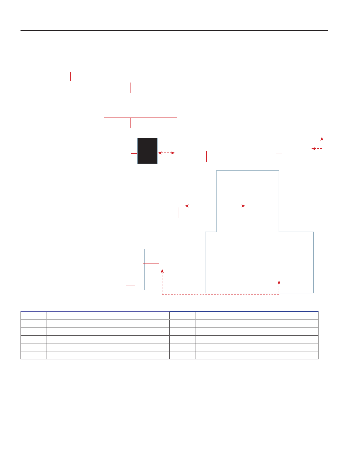
Right Side
Right side features (multiple models shown).
Label Description Label Description
A Drawer stop panel E Agitator communication setting
B Agitator speed control (stand-alone conguration only) F Data cable port
C Alarm volume control G Communication cable (for use with Pro Series Incubator)
D Alarm delay control
FEDC
B
A
G

Helmer Scientic i.Series®- Platelet Agitator Operation Manual
360390/A 16

Helmer Scientic
14400 Bergen Boulevard, Noblesville, IN 46060 USA
Copyright © 2018 Helmer, Inc. 360390/A
This manual suits for next models
3
Table of contents
Other Helmer Laboratory Equipment manuals


Popular Laboratory Equipment manuals by other brands

Biotage
Biotage TurboVap P+ quick start guide

Texas Instruments
Texas Instruments TD1000 Assembly instructions

Matec
Matec CHDF 2000 Hardware manual

Heidolph
Heidolph Multifarious Hei-SHAKE Unimax 1010 operating instructions

Scilogex
Scilogex SCI-T6-Pro user manual

Piezotronics
Piezotronics IMI Sensors 699B06 Installation and operating manual


