manuals.online logo
Brands
  1. Home
  2. •
  3. Brands
  4. •
  5. Edwards
  6. •
  7. Control Unit
  8. •
  9. Edwards SIGA-IM2 Assembly instructions

Edwards SIGA-IM2 Assembly instructions

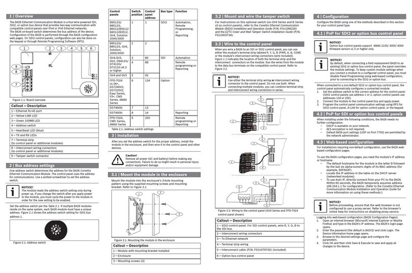
© 2020 Carrier 1 / 3 P/N 3102697-EN • REV 001 • ISS 24AUG20
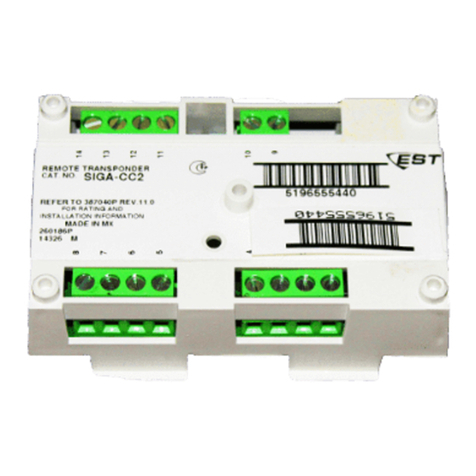
SIGA-IM2 Isolator Module
Installation Sheet
Description
The SIGA-IM2 Isolator Module is an addressable device that protects a
signaling line circuit (SLC) from a wire-to-wire short. The SIGA-IM2
module monitors line voltages and opens the SLC when a short is
detected, effectively isolating the short between the two isolator
modules located electrically closest to the short.
The SIGA-IM2 module requires one detector address on the SLC.
Addresses are assigned electronically. There are no address switches.
An LED provides visible indication of the status of the module:
• Normal: Green LED flashes
Installation
Install this device in accordance with applicable national and local
codes, ordinances, and regulations.
• NFPA 72 2013 – A single fault on a pathway connected to the
addressable devices shall not cause the loss of more than 50
addressable devices.
• NFPA 72 2016 and later – A single fault on a pathway connected
to the addressable devices shall not cause the loss of the devices
in more than one zone.
Notes
• The module is shipped from the factory as an assembled unit; it
contains no user-serviceable parts and should not be
disassembled.
• This module does not operate without electrical power. As fires
frequently cause power interruption, discuss further safeguards
with your local fire protection specialist.
To install the module:
1. Write the address assigned to the module on the label provided,
and then apply the label to the module. Remove the serial number
label from the module, and then attach it to the project
documentation.
2. Wire the module as shown in Figure 2 on page 2.
3. Using the self-tapping screw provided, attach the wall plate to the
module. See Figure 1.
4. Using the four machine screws provided, attach the wall plate and
module to the electrical box.
Figure 1: Installation diagram
(1) Compatible electrical box
(2) SIGA-IM2 module
(3) Wall plate
(4) #6-32 × 5/8 machine screws (4X)
(5) #4 × 1/2 self-tapping screw
Wiring
Wire this device in accordance with applicable national and local
codes, ordinances, and regulations.
Notes
• Refer to the Signature loop controller installation sheet for SLC
wiring specifications for additional details.
• All wiring is power-limited and supervised.
To wire the module:
1. Verify that all field wiring is free of opens, shorts, and ground
faults.
2. Strip 1/4 in. (about 6 mm) from the ends of all wires that connect to
the terminal block of the module.
When stripping wire ends, exposing more wire may cause a
ground fault; exposing less wire may result in a faulty connection.
3. Make all wiring connections as shown in Figure 2.
Figure 2: Wiring diagram
(1)
(2)
(3)
(4)
(5)
SLC

S
L
C

SLC

S
L
C

2 / 3 P/N 3102697-EN • REV 001 • ISS 24AUG20
Application
For Class A pathways, install SIGA-IM2 modules to segment the SLC
as required (e.g., by zone or by number of devices) to prevent a wire-
to-wire short from taking down the entire circuit. See Figure 3 and
Figure 4.
For Class X pathways (see Figure 5):
• Install a SIGA-IM2 module on the Class B out and Class A return
wiring inside the control unit, or in the same room, within 20 ft.
(6.1 m), and wiring enclosed in conduit or equivalently protected
against mechanical injury.
• Install a SIGA-IM2 module on both sides of one or more standard
mount modules contained in a common enclosure.
• Install a SIGA-IM2 module on both sides of a single standard
mount module, in the same room, within 20 ft. (6.1 m), and wiring
enclosed in conduit or equivalently protected against mechanical
injury.
• Install a SIGA-IM2 module on both sides of a common enclosure
containing one or more UIO plug-in modules, in the same room,
within 20 ft. (6.1 m), and wiring enclosed in conduit or equivalently
protected against mechanical injury.
Figure 3: Typical Class A with isolated Class B branches
(1) Non-isolated devices effectively removed from the circuit
(2) Short circuit
(3) SLC Class B out
(4) SLC Class A return
Figure 4: Typical Class A with isolators
(1) Non-isolated devices effectively removed from the circuit
(2) Short circuit
(3) SLC Class B out
(4) SLC Class A return
Figure 5: Typical Class X
(1) Common enclosure
(2) Standard mount module
(3) UIO plug-in module
(4) Field wiring in the same room, within 20 ft. (6.1 m), and enclosed
in conduit or equivalently protected against mechanical injury
(5) Automatic fire detectors attached to isolator bases
(6) SLC Class B out
(7) SLC Class A return
SLC
A+ A-
SLC
B+ B-
(1)
(2)
(3) (4)
FACU
IM2
IM2
IM2
IM2
SLC
A+ A-
SLC
B+ B-
(1
)
(2)
(3) (4)
FACU
IM2
IM2 IM2
IM2
SLC
A+ A-
SLC
B+ B-
(6) (7)
FACU
IM2 IM2
(2)
(4)
(2)
(4)
(4) (4)
(3)
(1)
(1)
(5)
(5)
(2)
IM2 IM2
IM2 IM2IM2
IM2IM2 IM2
P/N 3102697-EN • REV 001 • ISS 24AUG20 3 / 3
Specifications
Operating voltage 15.20 to 19.95 VDC
Current
Standby
Active
170 µA
427.5 µA
Circuit resistance between
isolators
6 Ωmax.
Ground fault impedance 10 kΩ
Circuit designation
Signaling line circuit
Class A, Class X
Wire size 12 to 18 AWG (1.0 to 4.0 mm²)
Compatible electrical boxes 2-1/2 in. (64 mm) deep double-gang
box; 4 in. square box, 1-1/2 in. (38 mm)
deep with double-gang cover
Operating environment
Temperature
Relative humidity
32 to 120°F (0 to 49°C)
0 to 93% noncondensing
Storage temperature range −4 to 140°F (−20 to 60°C)
Regulatory information
FCC compliance This device complies with part 15 of the FCC
Rules. Operation is subject to the following two
conditions: (1) This device may not cause harmful
interference, and (2) this device must accept any
interference received, including interference that
may cause undesired operation.
Contact information
For contact information, see www.edwardsfiresafety.com.

Other Edwards Control Unit manuals

Edwards SCU-800 User manual

Edwards

Edwards SCU-800 User manual

Edwards Speedivalve SP5 User manual

Edwards

Edwards Speedivalve SP5 User manual

Edwards SCU-750 User manual

Edwards

Edwards SCU-750 User manual

Edwards CTM City Tie Module Assembly instructions

Edwards

Edwards CTM City Tie Module Assembly instructions

Edwards IPVA10EK User manual

Edwards

Edwards IPVA10EK User manual

Edwards QSB63 User manual

Edwards

Edwards QSB63 User manual

Edwards LCPV16EKA User manual

Edwards

Edwards LCPV16EKA User manual

Edwards PVEK Series User manual

Edwards

Edwards PVEK Series User manual

Edwards D-397-54-000 User manual

Edwards

Edwards D-397-54-000 User manual

Edwards QSB63 User manual

Edwards

Edwards QSB63 User manual

Edwards LCPV16EKA User manual

Edwards

Edwards LCPV16EKA User manual

Edwards PV10/16EK User manual

Edwards

Edwards PV10/16EK User manual

Edwards GV Series User manual

Edwards

Edwards GV Series User manual

Edwards SCU-350 Series User manual

Edwards

Edwards SCU-350 Series User manual

Edwards GSA-CC1 Assembly instructions

Edwards

Edwards GSA-CC1 Assembly instructions

Edwards 3-24R Assembly instructions

Edwards

Edwards 3-24R Assembly instructions

Edwards IBV16MKS User manual

Edwards

Edwards IBV16MKS User manual

Edwards IPVA10EK User manual

Edwards

Edwards IPVA10EK User manual

Edwards TCU 40/80 User manual

Edwards

Edwards TCU 40/80 User manual

Edwards SCU-XL800 User manual

Edwards

Edwards SCU-XL800 User manual

Edwards SCU-1601 User manual

Edwards

Edwards SCU-1601 User manual

Edwards SIGA-CC2A User manual

Edwards

Edwards SIGA-CC2A User manual

Edwards LCPVEK Series User manual

Edwards

Edwards LCPVEK Series User manual

Edwards 3-ASU Assembly instructions

Edwards

Edwards 3-ASU Assembly instructions

Popular Control Unit manuals by other brands

Burkert 5406 manual

Burkert

Burkert 5406 manual

Renesas RL78/G1D user manual

Renesas

Renesas RL78/G1D user manual

Grundig GSS SID 162 Assembly instruction

Grundig

Grundig GSS SID 162 Assembly instruction

Interlogix TruPortal TP-ADD-2D-BRD quick reference

Interlogix

Interlogix TruPortal TP-ADD-2D-BRD quick reference

Honeywell IDENT-KEY Series Mounting and Connection Instructions

Honeywell

Honeywell IDENT-KEY Series Mounting and Connection Instructions

ICP DAS USA iWSN-110X Series quick start

ICP DAS USA

ICP DAS USA iWSN-110X Series quick start

SolarEdge ZigBee Plug-in installation guide

SolarEdge

SolarEdge ZigBee Plug-in installation guide

Hasco Hotrunner H1270 Series operating instructions

Hasco

Hasco Hotrunner H1270 Series operating instructions

Isel iPC15 Operating	 instruction

Isel

Isel iPC15 Operating instruction

National Instruments 9512 C Series Getting started

National Instruments

National Instruments 9512 C Series Getting started

Bosch BCM-0000-B installation guide

Bosch

Bosch BCM-0000-B installation guide

Altera Stratix III Series Device handbook

Altera

Altera Stratix III Series Device handbook

PI Q-Motion Q-545 Series user manual

PI

PI Q-Motion Q-545 Series user manual

Elkron DK510M-P manual

Elkron

Elkron DK510M-P manual

TraceTek TTDM-128 user manual

TraceTek

TraceTek TTDM-128 user manual

Hi-Link HLK-7628N user manual

Hi-Link

Hi-Link HLK-7628N user manual

Pfeiffer Vacuum EVC 116 M operating manual

Pfeiffer Vacuum

Pfeiffer Vacuum EVC 116 M operating manual

hyfire TAURUS TAU-MO-SB-01 quick start guide

hyfire

hyfire TAURUS TAU-MO-SB-01 quick start guide

manuals.online logo
manuals.online logoBrands
  • About & Mission
  • Contact us
  • Privacy Policy
  • Terms and Conditions

Copyright 2025 Manuals.Online. All Rights Reserved.