KIESELMANN 6268 User manual

Type 6268
for gas
spring loaded
with and without safety function
Operating instruction
Translation of the original
Bunging valves
PDF • ak • 30/09/2019
GB
ENGLISH

KIESELMANN GmbH
Paul-Kieselmann-Str. 4-10
75438 Knittlingen
( +49(0) 7043 371-0 • 7 +49(0) 7043 371-125
www.kieselmann.de • [email protected]
Copyright: © KIESELMANN FLUID PROCESS GROUP

KIESELMANN GmbH Table of contents
6268_EN III
Table of contents
1 General informations ....................................................................................................................................................4
1.1 Informations for your safety ...............................................................................................................................................4
1.2 Marking of security instructions.........................................................................................................................................4
1.3 General designated use ......................................................................................................................................................4
1.4 Personnel .............................................................................................................................................................................4
1.5 Modifications, spare parts, accessories ............................................................................................................................5
1.6 General instructions ............................................................................................................................................................5
2 Safety instructions........................................................................................................................................................6
2.1 Intended use ........................................................................................................................................................................6
2.2 General notes.......................................................................................................................................................................6
2.3 General safety instructions.................................................................................................................................................6
3 Delivery, transport and storage .....................................................................................................................................8
3.1 Delivery.................................................................................................................................................................................8
3.2 Transport..............................................................................................................................................................................8
3.3 Storage.................................................................................................................................................................................8
4 Function and operation .................................................................................................................................................9
4.1 Description of function........................................................................................................................................................9
4.2 Manual operation ................................................................................................................................................................9
4.3 Pressure setting...................................................................................................................................................................9
5 Commissioning, service and maintenance ..................................................................................................................10
5.1 Commissioning..................................................................................................................................................................10
5.1.1 Installation instructions....................................................................................................................................... 10
5.1.2 General welding guidelines ................................................................................................................................. 10
5.1.3 ATEX - Guidelines ................................................................................................................................................ 10
5.2 Service................................................................................................................................................................................10
5.3 Cleaning .............................................................................................................................................................................11
6 Technical data ............................................................................................................................................................12
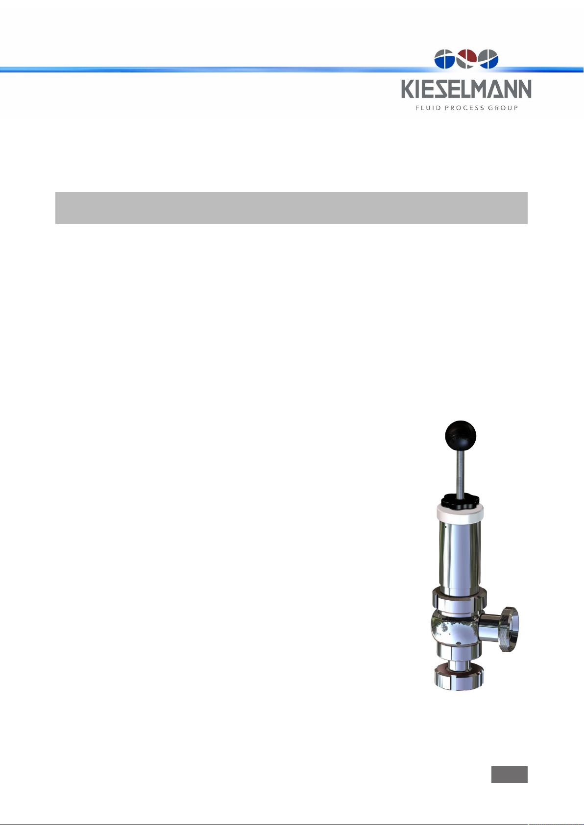
6.1 Bunging valve Type 6268..................................................................................................................................................12
6.2 Identification......................................................................................................................................................................12
7 Disassembly and assembly .........................................................................................................................................13
7.1 Disassembly.......................................................................................................................................................................13
7.2 Assembly ...........................................................................................................................................................................14
8 Drawings and dimensions ...........................................................................................................................................15
8.1 Drawings ............................................................................................................................................................................15
8.2 Dimensions ........................................................................................................................................................................16
9 Wearing parts .............................................................................................................................................................17
9.1 Wearing parts list...............................................................................................................................................................17
10 Characteristic curves ..................................................................................................................................................18
10.1 Performance chart ............................................................................................................................................................18
11 Appendix ....................................................................................................................................................................24
11.1 Declaration of incorporation.............................................................................................................................................24

Operating instruction | KIESELMANN GmbH1 | General informations
4 / 24 6268_EN
1 General informations
1.1 Informations for your safety
We are pleased that you have decided for a high-class KIESELMANN GmbH product. With correct
application and adequate maintenance, our products provide long time and reliable operation.
Before installation and initiation, please carefully read this instruction manual and the security ad-
vices contained in it. This guarantees reliable and safe operation of this product and your plant re-
spectively. Please note that an incorrect application of the process components may lead to great
material damages and personal injury.
In case of damages caused by non observance of this instruction manual, incorrect initiation, hand-
ling or external interference, guarantee and warranty will lapse!
Our products are produced, mounted and tested with high diligence. However, if there is still a
reason for complaint, we will naturally try to give you entire satisfaction within the scope of our war-
ranty. We will be at your disposal also after expiration of the warranty. In addition, you will also find
all necessary instructions and spare part data for maintenance in this instruction manual. If you
don't want to carry out the maintenance by yourself, our KIESELMANN GmbH - service team will
naturally be at your disposal.
1.2 Marking of security instructions
Hints are available in the chapter "safety instructions" or directly before the respective operation in-
struction. The hints are highlighted with a danger symbol and a signal word. Texts beside these
symbols have to be read and adhered to by all means. Please continue with the text and with the
handling at the valve only afterwards.
Symbol Signal word Meaning
DANGER Imminent danger which will result severe personal injury or
death.
WARNING Imminent danger which may result severe personal injury or
death.
CAUTION Dangerous situation which may cause slight personal injury or
material damages.
NOTICE An harmful situation which may result in damages of the product
itself or of adjacent vicinity.
INFORMATION Marks application hints and other information which is particu-
larly useful.
1.3 General designated use
The fitting is designed exclusively for the purposes described below. Using the fitting for purposes
other than those mentioned is considered contrary to its designated use. KIESELMANN GmbH can-
not be held liable for any damage resulting from such use. The risk of such misuse lies entirely with
the user. The prerequisite for the reliable and safe operation of the fitting is proper transportation
and storage as well as competent installation and assembly. Operating the fitting within the limits
of its designated use also involves observing the operating, inspection and maintenance instruc-
tions.
1.4 Personnel
Personnel entrusted with the operation and maintenance of the tank safety system must have the
suitable qualification to carry out their tasks. They must be informed about possible dangers and
must understand and observe the safety instructions given in the relevant manual. Only allow quali-
fied personnel to make electrical connections.

KIESELMANN GmbH | Operating instruction General informations | 1
6268_EN 5 / 24
1.5 Modifications, spare parts, accessories
Unauthorized modifications, additions or conversions which affect the safety of the fitting are not
permitted. Safety devices must not be bypassed, removed or made inactive. Only use original spare
parts and accessories recommended by the manufacturer.
1.6 General instructions
The user is obliged to operate the fitting only when it is in good working order. In addition to the in-
structions given in the operating manual, please observe the relevant accident prevention regula-
tions, generally accepted safety regulations, regulations effective in the country of installation,
working and safety instructions effective in the user's plant.

Operating instruction | KIESELMANN GmbH2 | Safety instructions
6 / 24 6268_EN
2 Safety instructions
2.1 Intended use
The bunging valve is primarily intended to be used to hold the pressure of gaseous media in tanks
and containers consistently and to prevent over-pressures if the safety function is set.
2.2 General notes
NOTICE - observe the operating instructions
To avoid danger and damage, the fitting must be used in accordance with the safety instructions
and technical data contained in the operating instructions.
NOTICE
All data are in line with the current state of development. Subject to change as a result of tech-
nical progress.
2.3 General safety instructions
WARNING
Risk of injury by outflowing medium
Dismantling the valve or valve assemblies from the plant can cause injuries.
– Medias flowing through the leakage drain outlet are to be drained off without splashing
into a discharge arrangement.
– Carry the disassembling only if when the plant has been rendered pressure-less and free
of liquid and gas.
WARNING
Risk of injury by outflowing medium
With pressure greater than the set pressure the gaseous or liquid media will radial escape into the
atmosphere via outlet drillings.
– It is necessary to install protection and drainage devices.
WARNING
Functional impairment at low temperatures
Referring to the used sealing materials the vacuum valves are suitable for a minimum operating
temperature at -10 °C.
ØLow operating or ambient temperatures may applicable a impairment the function.
– Therefore, appropriate measures shall be taken for an operation at temperatures below
+5°C to ensure a safe function of the valve.
WARNING
ATEX - Guidelines
If the valve or the plant is operated in a potentially explosive atmosphere, the valid ATEX directive of
the EC and the installation instructions in this operating manual must be observed.
CAUTION
Before starting the system, the entire pipeline system must be thoroughly cleaned.

KIESELMANN GmbH | Operating instruction Safety instructions | 2
6268_EN 7 / 24
CAUTION
Steps should be taken to ensure that no external forces are exerted on the fitting.
CAUTION
Malfunction due to contamination
Internal or external dirt may impair the function of the fitting or the safety equipment.
ØTherefore the fitting must be operated in a way that protects it from external influences.
– The fitting must be cleaned internal and external at regular intervals.
– The fitting must be maintained at regular intervals.
– The fitting must be checked for its function at regular intervals.

Operating instruction | KIESELMANN GmbH3 | Delivery, transport and storage
8 / 24 6268_EN
3 Delivery, transport and storage
3.1 Delivery
• Immediately after receipt check the delivery for completeness and transport damages.
• Remove the packaging from the product.
• Retain packaging material, or expose of according to local regulations.
3.2 Transport
CAUTION
Risk of injury and damage to the product
During the transport the generally acknowledged rules of technology, the national accident preven-
tion regulationsand company internal work and safety regulations must be observed.
3.3 Storage
NOTICE
Damage to the product due to improper storage!
Observe storage instructions
avoid a prolonged storage
INFORMATION
Recommendation for longer storage
We recommend regularly checking the product and the prevailing storage conditions during long
storage times.
• To avoid damage to seals and bearings,
– products up to DN 125 / OD 5 inch should be stored horizontally for maximum 6 months.
– products larger than DN 125 / 5 inch, should be stored in the upright position with the actu-
ator on top.
• Don't store any objects on the products.
• Protect the products for wetness, dust and dirt.
• The product should be stored in a dry and well ventilated room at a constant temperature (op-
timal indoor temperature: 25 C ±5; indoor humidity data 70% ±5%).
• Protect seals, bearings and plastic parts for UV light and ozone.

KIESELMANN GmbH | Operating instruction Function and operation | 4
6268_EN 9 / 24
4 Function and operation
4.1 Description of function
The valve opens against spring force if the set pressure is crossed. It closes if the current pressure
drops under the set pressure (see Characteristic curves)
Optional: For valves with safety function(DN15, DN25), a locking sleeve prevents, that the pre-
scribed maximum pressure within the set range will be exceeded.
4.2 Manual operation
M
The manual lifting device serves to manually actuate the valve.
• Short term lifting of the valve takes place by pulling on the spindle (3) via the spherical button
(11) and/or the lifting nut (10) in the direction X. This will raise the valve and the medium dis-
perses via outlet B.
• For a longer lifting of the valve (e.g. when cleaning), the lifting nut (10) is turned in a clockwise
direction to the adjusting nut (9). Now mark (M) the position with a pen/pencil. nscrew the ad-
justing nut (9) anticlockwise using 2 complete turns. The valve will be raised and the medium
disperses via outlet B.
In order to close the valve, the adjusting nut (9) is turned in an anticlockwise direction using 2 com-
plete turns as far as the mark. Screw the lifting nut (10) anticlockwise as far as the spherical button
(11) and tighten.
4.3 Pressure setting
The set pressure can be adjusted to scaling in the pressure area by longitudinal positioning of the
adjustment nut (9). The positioning is done by rotary motion via a thread.
Optional: For valves with safety function, the adjustment nut is turned up to the locking sleeve, so
that the prescribed maximum pressure within the set range will be not exceeded.
CAUTION
Valve plate don't close
The positioning of the lifting nut is tightened in the operating mode using the spherical button. Were
the lifting to come and rest upon the adjusting nut the valve would not close tight enough to ensure
a seal against the leakage of fluids.

Operating instruction | KIESELMANN GmbH5 | Commissioning, service and maintenance
10 / 24 6268_EN
5 Commissioning, service and maintenance
5.1 Commissioning
5.1.1 Installation instructions
A
Fitting position
The bung valve must be installed vertically at connection "A" (see figure).
Functional check
After installation or after manual actuation of the valve, the closing function and the function in the
operating state must be checked in accordance with the specified performance data.
5.1.2 General welding guidelines
Sealing elements integrated in weld components must generally be removed prior to welding. To
prevent damage, welding should be undertaken by certified personnel (EN ISO 9606-1). Use the TIG
(Tungsten Inert Gas) welding process.
CAUTION
Damage and injuries due to high temperature supply
To avoid a distortion of the components, all welding parts must be welded to stress-relieved.
Allow all components to cool before assembling.
NOTICE
Damage due to impurities
Impurities can cause damage to the seals and seals area.
Clean inside areas prior to assembly.
5.1.3 ATEX - Guidelines
For valves or plants/installations that are operated in the ATEX area, sufficient bonding (grounding)
must be ensured (see valid ATEX Guidelines EG).
5.2 Service
RECOMMENDATION
Replacement of seals
To achieve optimal maintenance cycles, the following points must be observed!
– When replacement of seals, all product-contacting seals should be replaced.
– Only original spare parts may be installed.
Maintenance interval
The maintenance intervals depend on the operating conditions "temperature, temperature-intervals,
medium, cleaning medium, pressure and opening frequency". We recommend replacing the seals 1-
year cycle The user, however should establish appropriate maintenance intervals according to the
condition of the seals.

KIESELMANN GmbH | Operating instruction Commissioning, service and maintenance | 5
6268_EN 11 / 24
Lubricant recommendation
EPDM; HNBR; NBR; FKM; k-flex - Klüber Paraliq GTE703*
Silicone - Klüber Sintheso pro AA2*
Thread - Interflon Food*
*) It is only permitted to use approved lubricants, if the respective fitting is used for the produc-
tion of food or drink. Please observe the relevant safety data sheets of the manufacturers of lub-
ricants.
5.3 Cleaning
Cleaning
The optimum cleaning is carried out with the tank or pipe cleaning.
For this, open and close the valve several times.

Operating instruction | KIESELMANN GmbH6 | Technical data
12 / 24 6268_EN
6 Technical data
6.1 Bunging valve Type 6268
Model bunging valve
• DN 15 / 25 Bunging valve with and without safety function
• DN 25 / 32 Bunging valve with and without safety function
• DN 40 / 50 Bunging valve without safety function
Valve size DN50 - DN250
Connection • Liner / nut DIN11581
• Thread DIN 11851
Leak rate A (DIN EN 12266-1)
Temperature range Operating temperature:
(medium dependent)
+4° to +95°C
Sterilization temperature:
(SIP 30 min)
EPDM +140°C
Material:
(in product contact)
stainless steel: 1.4404 / AISI 316L
1.4301 / AISI 304
Surface: Ra ≤ 0,8µm mat finish
Sealing material: • EPDM (FDA)
Adjusting range Nominal diameter Working area
(bar)
Opening-/Permissible clos-
ing differential
DN15
-
DN40
0.2 - 2.0 ± 0,1 bar (>2 bar ± 10 %)
0.5 - 3.0 ± 0,1 bar (>2 bar ± 10 %)
1.2 - 3.0 ± 0,1 bar (>2 bar ± 10 %)
1.5 - 4.0 ± 0,1 bar (>2 bar ± 10 %)
Safety function
Set pressure (bar)
discharge coefficient αw
DN 15 DN 25 DN 40
2.0 0.36 0.18 -
3.0 0.35 0.23 -
4.0 0.34 0.26 -
6.2 Identification
set
Made in the EU
Ts -xx°C/+xxx°C
xxxxxxxxxx-xxxSerial no.
Order no. xxxxxxxx / xx
Norm
Date
cross section
Material
Manufacturer Logo
Serial number
Order number
Nominal diameter
Set pressure A 314 mm²
MM/JJJJ
DN xx / DN xx A xxxx mm²
2
AISI xxxx
Operating temperature

KIESELMANN GmbH | Operating instruction Disassembly and assembly | 7
6268_EN 13 / 24
7 Disassembly and assembly
7.1 Disassembly
Replacement wear parts (D1), (D2), (D3)
• Screw the lifting nut (10) down to
the adjustment nut (9) and screw
for another 2-3 turns so that the
valve plate is raised from the seal
seat.
• Unscrew the slotted nut (6).
• Remove valve insert from housing
(VG).
• Unscrew the spherical button (11)
and lifting nut (10).
• Carefully pull the pisten (2) with
spindle (3) from the spring housing
(5).
NOTICE
When pulling the spindle (3) from the spring housing (5), make sure that the thread of the spindle
does not damage the bearing (4) or the lip seal (D2).
The piston (2) is joined to the spindle with a high-strength screw locking device and must not be
disassembled.
• Re-clamp the spindle at position (F) (see Fig. /page [}15]) in the vice between the soft jaws.
• Unscrew the piston plate (1) above the width flat SW1 and remove the O-ring (D1).
• Remove the O-ring (D3) and the lip seal (D2).
Dismantle the pressure spring
• Unscrew the adjustment nut (9) from the spring housing (5). The pressure spring will relax.
• Remove the slotted nut (6), spring guide (12) (depending on the model), spring (8) and the
spring plate (7).

Operating instruction | KIESELMANN GmbH7 | Disassembly and assembly
14 / 24 6268_EN
7.2 Assembly
• Before installation, thoroughly clean and slightly lubricate mounting areas and running sur-
faces.
• Assemble in reverse order.
NOTICE
Assembly O-Ring (D1)
The installation spaces on the piston (2) and the piston plate (1) have to be carefully cleaned and
slightly lubricated.
Clamp the spindle (3) between the soft jaws in the vice and clamp onto the surface (F) (see Fig. /
page [}15]).
Dampen the O-ring (D1) slightly with suitable grease and insert into the piston (2).
Screw in the piston plate (1) as far as the metallic arrester and make sure that the O-ring (D1) does
not rotate with it or twist.
• Check the function according to the specified performance data in the operating state.

KIESELMANN GmbH | Operating instruction Drawings and dimensions | 8
6268_EN 15 / 24
8 Drawings and dimensions
8.1 Drawings
1. Piston plate
2. Piston
3. Spindle
4. Plain bearing
5. Spring housing
6. Slotted nut
7. Spring disc
8. Compression spring
9. adjusting nut
10. lifting nut
11. spherical button
12. Spring guide
13. Locking sleeve
(only for valves with safety
function)
VG) Housing
G) Screw retention high strength
F) Clamping surface
SW) Spanner flat

Operating instruction | KIESELMANN GmbH8 | Drawings and dimensions
16 / 24 6268_EN
8.2 Dimensions
DN D1 D2 Rd1 Rd2 L1 L2 L3 L4 M
Assembly dimen-
sion
15 / 25 16 26 Rd34x1/8 Rd52x1/8 275 77 61.5 283.5 335
25 / 32 26 32 Rd52x1/6 Rd58x1/6 278 72 72 291.5 345
40 / 50 38 50 Rd65x1/6 Rd78x1/6 286 74 91 319 360

KIESELMANN GmbH | Operating instruction Wearing parts | 9
6268_EN 17 / 24
9 Wearing parts
9.1 Wearing parts list
DN
Pos. Designation Material: 15 / 25 25 / 32 40 / 50
Seal kit (D1-D3) EPDM 6268 016
993-000
6268 026
993-000
6268 041
993-000
D1 O-ring EPDM 2304 021
040-170
2304 021
040-170
2304 032
040-069
D2 lip seal EPDM 2330 016
007-054
2330 016
007-054
2330 016
007-054
D3 O-ring EPDM 2304 042
025-170
2304 042
025-170
2304 042
025-170
4 Plain bearing JSM-1622-16 8050 016
016-156
8050 016
016-156
8050 016
016-156

Operating instruction | KIESELMANN GmbH10 | Characteristic curves
18 / 24 6268_EN
10 Characteristic curves
10.1 Performance chart
Flow capacity
Bunging valve DN15/25 | DN25/32 | DN40/50 Set pressure: 0,20-2,00 bar (air 20°C)
Set pressure
(bar)
Closing pressure
(bar)
Flow rate (m³/h)
+ 0,1bar + 0,15bar + 0,2bar
0.20 - 2.00 DN
15/25
DN
25/32
DN
40/50
DN
15/25
DN
25/32
DN
40/50
DN
15/25
DN
25/32
DN
40/50
DN
15/25
DN
25/32
DN
40/50
0.20 0.17 0.17 0.16 45.2 52.0 12.6 90.5 108.6 82.3 117.6 156.0 126.7
0.40 0.34 0.32 0.36 90.5 119.6 33.4 119.4 162.9 105.8 135.7 201.0 133.9
0.60 0.55 0.54 0.53 117.6 116.2 27.1 135.7 150.2 109.5 153.8 191.8 144.8
0.80 0.73 0.77 0.70 144.8 115.3 117.6 171.9 148.6 139.3 181.9 209.6 173.7
1.00 0.92 0.96 0.91 140.2 138.1 92.31 180.1 198.2 123.0 186.4 251.5 161.0
1.20 1.10 1.15 1.12 171.9 140.2 122.1 185.5 209.9 141.1 199.1 258.2 159.2
1.40 1.32 1.33 1.32 181.0 177.4 72.4 199.1 235.0 142.0 208.1 255.4 194.5
1.60 1.51 1.49 1.50 208, 160.1 103.1 215.3 234.4 153.8 228.9 253.4 200.0
1.80 1.67 1.73 1.70 229.8 171.9 124.8 235.3 237.1 161.0 244.3 248.8 187.3
2.00 1.88 1.93 1.90 244.3 232.5 139.3 248.8 258.8 208.1 251.5 277.8 218.1
Flow capacity [m³/h]
Set pressure [bar]

KIESELMANN GmbH | Operating instruction Characteristic curves | 10
6268_EN 19 / 24
Flow capacity [m³/h]
Set pressure [bar]
Flow capacity [m³/h]
Set pressure [bar]

Operating instruction | KIESELMANN GmbH10 | Characteristic curves
20 / 24 6268_EN
Bunging valve DN15/25 | DN25/32 | DN40/50 Set pressure: 0,50 - 3,00 bar (air 20°C)
Set pressure
(bar)
Closing pressure
(bar)
Flow rate (m³/h)
+ 0,1bar + 0,15bar + 0,2bar + 0,3bar
0.50 - 3.00 DN
15/25
DN
25/32
DN
40/50
DN
15/25
DN
25/32
DN
40/50
DN
15/25
DN
25/32
DN
40/50
DN
15/25
DN
25/32
DN
40/50
DN
15/25
DN
25/32
DN
40/50
0.50 0.47 0.44 0.46 19.01 104.0 19.0 118.5 142.1 60.99 127.6 188.5 107.6 x x x
0.75 0.68 0.69 0.69 55.21 123.8 19.5 126.7 156.2 67.41 144.8 213.4 136.7 x x x
1.00 0.92 0.90 0.94 173.7 157.2 18.1 190.0 190.6 99.55 199.1 236.3 130.3 x x x
1.25 1.14 1.16 1.17 181.0 174.4 10.8 194.5 222.0 90.50 202.7 255.4 147.5 x x x
1.50 1.41 1.38 1.42 181.0 156.2 14.4 198.2 218.2 110.4 216.3 257.3 150.2 x x x
1.75 1.66 1.64 1.67 198.6 174.6 20.8 225.9 235.3 113.1 237.3 265.1 163.8 x x x
2.00 1.88 1.90 1.90 x x x x x x 260.1 268.1 173.7 274.6 389.4 238.0
2.25 2.17 2.16 2.12 x x x x x x 308.6 206.3 191.8 325.8 389.1 244.3
2.50 2.37 2.42 2.35 x x x x x x 281.4 295.9 238.9 314.9 434.4 257.9
2.75 2.61 2.65 2.60 x x x x x x 304.9 334.8 234.4 360.1 407.2 267.8
3.00 2.88 2.82 2.88 x x x x x x 337.5 331.2 207.2 364.7 477.8 253.4
Flow capacity [m³/h]
Set pressure [bar]
Table of contents
Other KIESELMANN Control Unit manuals

KIESELMANN
KIESELMANN 582x User manual

KIESELMANN
KIESELMANN 5714 User manual

KIESELMANN
KIESELMANN 5091 User manual

KIESELMANN
KIESELMANN 91 Series User manual

KIESELMANN
KIESELMANN 6125 User manual

KIESELMANN
KIESELMANN 5629 Series User manual

KIESELMANN
KIESELMANN 403 Series User manual

KIESELMANN
KIESELMANN 6155 User manual

KIESELMANN
KIESELMANN 567 Series User manual

KIESELMANN
KIESELMANN 5093 xxx 000 series User manual