Henry Schein 900-8275 User manual

®
Pulsooxímetro de ma o
• Medida eficaz de la saturació de oxíge o y el pulso del pacie te
• para se sor portátil de dedo
Oxymètre de pouls de poche
• Appareil fiable mesura t la SpO2ai si que la fréque ce cardiaque du patie t
• avec le capteur par le biais
HS Ei ha dpulsoximeter
• Zuverlässige Sauerstoffsättigu gs- u d Herz freque z-Messu ge
• mit Fi gerse sor
HandHeld Pulse Oximeter
• reliable sPO2and Pulse rate measurements
• witH finger sensOr
900-8275
InstructIons for use
InstruccIones De uso
Manuel D’utIlIsatIon
GebrauchsanweIsunG
GebruIksaanwIjzInG
Distributed by: (US only)
!$*#$$!
EC REP
+++"!&(,)"!#&(& '%
Rev. 2011/12
3x1.5V AA


ENGLISH
ESPANOL
FRANCAIS
DEUTSCH
DUTCH

2
Copyright
Our company owns all rights of this unpublished work and intends to maintain it as a confidential work. We may
also seek to maintain this work as an unpublished copyright. This publication is to be used solely for the purpose
of reference or operation of our software system. No part of this work can be disseminated for other purposes.
In the event of inadvertent or deliberate publication, we intend to enforce its right to this work under copyright laws
as a published work. Those having access to this work may not copy, use, or disclose the information in this work
unless expressly authorized by our company.
All information contained in this publication is believed to be correct. We shall not be liable for errors contained
herein nor for incidental or consequential damages in connection with the furnishing, performance, or use of this
material. The information this publication refers to is protected by copyrights or patents and does not convey any
license under the patent rights of our company, nor the rights of others. We do not assume any liability arising out
of any infringements of patents or other rights of third parties.
Content of the manual is subject to change without prior notice.
All rights reserved.
Content
1 Introduction .................................................................. 2
1.1 Brief Introduction ............................................... 2
1.2 Safety Information............................................. 2
1.3 Intended Use..................................................... 3
1.4 Equipment Classification................................... 4
1.5 Explanation of Symbols..................................... 4
1.6 Product Features............................................... 4
2 General Description ..................................................... 4
2.1 Appearance ....................................................... 5
2.2 Power Supply .................................................... 5
3 ID, Time and Date Settings.......................................... 6
3.1 Date & Time Settings ........................................ 6
3.2 ID Number Setting............................................. 6
4 Take a Measurement ................................................... 6
4.1 Install The Probe ............................................... 6
4.2 Measurement Screens...................................... 7
4.3 Factors That May Affect The Measurement...... 7
5 Other Settings.............................................................. 8
5.1 Alarm Setup....................................................... 8
5.2 History ............................................................... 8
5.3 Voice Setup ....................................................... 9
5.4 System Setup.................................................. 10
6 Alarm...........................................................................11
7 Maintenance and Repair............................................ 12
7.1 Maintenance.................................................... 12
7.2 Safety Checks ................................................. 12
7.3 Calibration and Verification ............................. 13
7.4 Troubleshooting............................................... 13
7.5 Warranty and Repair ....................................... 14
APPENDIX A Specifications ......................................... 15
APPENDIX B Declaration of Manufacturer................... 16
1. Introduction
1.1 Brief Introduction
Thank you for purchasing the Henry Schein pulse oximeter. The main functions of the device include
Hemoglobin Saturation (SpO2) and pulse rate (PR) measurements, visual and audible alarm, probe off and
finger out alarm, data storage, transmitting and review etc. Please read this manual carefully before using the
device.
Notes㧦
oThe illustrations applied in the manual may differ slightly from the actual device.
oThe device is designed of handheld structure; please do not turn upside while in use.
1.2 Safety Information
Advisory Notes
oWarning - Indicates a potential hazard or unsafe practice that if carried out will result in death or serious
injury.
oCaution - Indicates a potential hazard or unsafe practice that if carried out could result in minor personal
injury or product/property damage.
oNote - Provides helpful tips or other useful information to ensure that you get the most from your product.
ENGLISH

3
Warnings!
oBefore putting the system into operation, verify that the equipment, connecting cables and accessories are
in correct working order and operating condition.
oTo avoid explosion hazard, do not use the pulse oximeter in an explosive atmosphere or in the presence
of flammable anesthetics, vapors or liquids.
oDo not use the pulse oximeter in an MRI or CT environment.
oThe pulse oximeter is intended only as an adjunct in patient assessment. It must be used in conjunction
with other methods of assessing clinical signs and symptoms.
oThe surface of the device can be wiped with alcohol gently. Do not allow to come into contact with
corrosive gases and liquids such as strong acid and alkali substance.
oDo not open the equipment housing; electric shock hazard may occur. All servicing and future upgrades
must be carried out by personnel trained and authorized by our company only.
oProlonged use of the probe/sensor or patient’s condition may require changing the sensor site periodically.
Change the sensor site and check skin integrity, circulatory status, and correct alignment at least every 4
hours. Prolonged use may cause blisters, skin deterioration, and discomfort.
oSensor malfunction may cause inaccurate data possibly resulting in patient injury or death, so pay close
attention to the sensor and inspect frequently.
oDo not rely only on the audible alarm system for patient monitoring. Adjustment of alarm volume to off may
result in anxiety to the patient. Remember that alarm settings should be customized according to different
patient situations.
oWhen using the equipment with electrosurgical units (ESU), make sure the patient is safe.
oDo not come into contact with the patient during defibrillation. Otherwise serious injury or death could
result. –NOT SURE I Understand this statements
oSingle-use accessories should not be reused.
oTo avoid inadvertent disconnection, ensure all cables and wires are in a secure and safe position. Wrap
and secure excess cabling to avoid risk of entanglement or hazard to patients or personnel.
Cautions
oAutoclaving, ethylene oxide sterilizing, or immersing the sensors in liquid may cause inaccurate readings.
oTo ensure patient safety, use only parts and accessories specified in this manual.
oThe operator must read and understand all the information in this manual before using the device.
oMagnetic and electrical fields are capable of interfering with the proper performance of the equipment. For
this reason make sure that all external devices operated in the vicinity of the equipment comply with the
relevant EMC requirements. Mobile phone, X-ray equipment or MRI devices are a possible source of
interference as they may emit higher levels of electromagnetic radiation.
oUnplug the sensor from the pulse oximeter before cleaning or disinfecting it.
oIf liquid is accidentally spilled on the unit, clean and dry thoroughly before re-use.
oDo not use SpO2and NIBP measurement on the same arm at the same time. This could potentially affect
measurement accuracy.
oThe disposal of the equipment, as well as its accessories, must be in compliance with the
guidelines/directives regulating the disposal of such products.
oAlways install or carry the equipment properly to avoid damage caused by drop, impact, strong vibration
or other mechanical force.
oAlarm must be set up according to different requirements of individual patients. Make sure that alarm
sound can be activated when alarm function begins to work.
Notes
oThe software was developed in compliance with IEC60601-1-4. The possibility of hazards arising from
software errors is therefore minimized.
oSpO2measurements may be influenced by high ambient light, especially sunlight. Shield the sensor area
if necessary.
oDyes introduced into the bloodstream, such as methylene blue, indocyanine green, indigo carmine, and
fluorescein, may influence the accuracy of the SpO2reading.
oAny condition that restricts blood flow, such as use of a blood pressure cuff or extremes in systemic
vascular resistance, may cause a failure to determine accurate pulse rate and SpO2readings.
oRemove fingernail polish or artificial fingernails before applying SpO2sensors. Fingernail polish or artificial
fingernails may cause inaccurate SpO2readings.
oOptical crosstalk (interference) can occur when two or more sensors are located in adjoining areas. It can
be eliminated by covering each site with opaque material. Optical crosstalk may adversely affect the
accuracy of the SpO2readings.
oObstructions or dirt on the sensor’s red light or detector may cause a sensor failure. Make sure there are
no obstructions and the sensor is clean.
oFor routine equipment maintenance, please refer to the service procedures at the associated section as
indicated in the manual.
oDispose of the device or its accessories at end of life in accordance with the local ordinances/regulations
or directives, otherwise, discarding them as you like may cause pollution to the environment.
oIt is not recommended to take measurements during battery charging.
oFederal Law restricts this device to sale by or on the order of a physician.
oAs to the other concerns for attention, please carefully look through the specific chapter in this instruction.
1.3 Intended Use
The Henry Schein handheld pulse oximeter is intended for continuous monitoring, spot-checking of functional
pulse oxygen saturation (SpO2) and pulse rate (PR) of single adult and pediatric patients in hospitals and
home care.
ENGLISH

4
1.4 Equipment Classification
Classification according to IEC-60601-1:
According to the type of protection against Electrical shock:
oInternal electrical power source equipment and class II equipment;
According to the degree of protection against Electrical shock:
oType BF equipment;
According to the degree of protection against harmful ingress of water:
oIPX1;
According to the methods of sterilization or disinfection:
oNon-sterilization, use liquid or wipe surface disinfectants only;
According to the mode of operation:
oContinuous operation
1.5 Explanation of Symbols
Symbol
Explanation
Symbol
Explanation
Type BF applied part
IPX1
Protected against dripping water
Attention, consult accompanying
documents
Prevent from rain
Date of Manufacture
Manufacturer’s information
Authorized representative in the
European community
European union approval
SN
Serial number
User ID
Connected with adapto
r
Battery power indication
Sound on
Sound off
Keyboard is unlocked
Keyboard is locked
USB cable is connected
USB cable disconnected
SpO
2probe is inserted
SpO
2
probe off
Storage temperature and
relative humidity
1.6 Product Features
oCompact and light in weight - simple to use.
oTFT displaying screen with adjustable backlight.
oUp to 127 user ID and 72-hour records storage.
oVisual and three-level audible alarms, low battery alarm.
oData transfer to PC by USB cable.
oPowered by three AA alkaline.
oBattery charge function with adapter or charge stand (optional).
2. General Descriptions
The handheld pulse oximeter adopts 2.4 inch TFT displaying screen. It can display the SpO2, PR value, pulse bar,
SpO2waveform and other kinds of parameters, such as the time, ID number, battery status and so on.
ENGLISH

5
2.1 Appearance
Fig.2-1
Description of Fig.2-1:
1. Connector for probe and USB cable: Used to connect with SpO2 probe and connect USB cable with PC
for data transmission.
2. SD card socket (reserved).
3. Alarm indicator: Will flash yellow when alarms occur.
4. Displaying screen.
5. Navigation buttons (UP, DOWN, LEFT, RIGHT): For selecting menu items and setting the parameters.
6. Menu button: For entering the main menu or sub menu, or confirming the selection/setting.
7. Power button: Press and hold the button for 3 seconds to power the device on, and for about 4 seconds to
power it off.
8. Connector for adaptor.
9. USB interface: Used for update the software, only serves engineers;
10. Side UP/DOWN button: Short press to increase/decrease the volume of alarm and beep; Extended press
to increase/decrease the brightness of the backlight.
If volume is reduced to level “0”, the sound is turned off - sound off indicator will appear
If brightness reduced to level “0”, means the system will be in sleep mode.
The following buttons can also be used as shortcut buttons:
oLEFT button: Press for extended time, both the audible alarm and pulse beep will be turned off; Press
again, these sound will be restored.
oMENU button: Press for extended time, the keyboard will be locked; Press again, the keyboard will be
unlocked.
oPower button: Short press under any screen will return to the main measurement screen.
2.2 Power Supply
The device can be powered by 3 AA alkaline batteries or power adaptor.
Rear panel introduction:
o1: Battery compartment
o2: Fixing hole
o3: Speaker for alarm
Fig.2-2 Rear Panel
2.2.1 Powered by batteries
Batteries Installation:
1. Open the battery cover: Rotate the fixing screw slightly in the rear panel to the position which is marked
with “ ” and then open the cover.
2. Batteries installation: Install 3 AA alkaline batteries as indicated by the polarity signs as shown in Fig.2-2.
Warning! Ensure the batteries are inserted in the correct polarities, as indicated by polarity markings inside the
battery compartment.
3. Close the battery cover: Close the battery cover and rotate the screw to the position to lock the cover.
You can open it with attached tool.
Battery life and replacement
When battery voltage is lower than 3.7±0.1V, the battery indicator will show as empty and red in color to
indicate that little battery capacity remains. You should replace the batteries with new ones immediately. When
ENGLISH

6
the battery voltage is lower than 3.5±0.1V the unit will shut down.
Cautions!
oDo not use batteries that are not specified for this unit.
oDo not dispose of batteries in fire.
oIf battery fluid should get on your skin or clothing, immediately rinse with plenty of clean water.
oRemove the batteries if the unit is not used for extended period. (Approximately three months or more).
oDo not use new and used batteries together.
oDispose of batteries in accordance with the local ordinances and regulations.
Warning!
DO NOT USE Ni-MH rechargeable and alkaline batteries together, otherwise, that may cause damage to the
device or injury to users.
Notes:
1. The “Brightness” cannot be set during the charging process.
2. It is not recommended to take measurements during the charging process, as this may damage the
device or possibly injure users.
3. DO NOT charge when the non-rechargeable batteries are installed, as this may damage the device or
possibly injure users.
3. ID, Time and Date Settings
Always set the date and time before using the unit for the first time. Set different ID numbers for different users.
The date and time are important indicators when a measurement is taken.
3.1 Date & Time Settings
Set the correct time according to the following steps:
1. Power on the pulse oximeter and then press the menu button to enter the main menu, refer to
Fig.3-1.
Fig.3-1 Fig.3-2 Fig.3-3
2. Select the “System Setup” item in the main menu; this will enter its corresponding sub-menu as
shown in Fig.3-2. Pick and enter the “Time/Date” item.
3. Pick different sub-items to set and press the MENU button to set and then press the Up or Down
button to adjust the value. Press the MENU button again to confirm your settings.
The date is displayed in the order of Year-Month-Day and Time is displayed Hour-Minute-Second.
3.2 ID Number Setting
Enter the “User ID Setup” item from the main menu screen, refer to Fig.3-1. Press the MENU button to place
ID number on as shown in Fig.3-4, and then press the UP or DOWN button to increase or decrease the ID
number, press the MENU button again to confirm your setting. The range of ID number is: 001-127.
Fig.3-4
4. Take a Measurement
4.1 Install the Probe
1. Before use, check the pulse oximeter for mechanical damage.
2. Insert the SpO2probe into the probe socket (refer to Fig.4-1). The indicator appears on the screen,
which indicates the probe is fully connected. If the SpO2probe is disconnected from the unit, the indicator
ENGLISH

7
will be shown and a prompt “Probe Off” will appear in the status bar in the top of the display screen.
Note: The connector is also applied when uploading data to Med View software for reviewing. For detailed
information, refer to the instruction manual of Med View software.
After loading the time and ID number setting, plug your finger into the sensor as shown in the following
illustration.
Fig 4-1 Fig.4-2 Placement of the sensor
3. Select the suitable sensor in terms of type and dimension.
4.2 Measurement Screens
There are two display modes as shown in the following pictures.
Fig.4-3(Digital Mode) Fig.4-4 (Wave Mode)
Description of measurement screens:
1. Meterage: The pulse oximeter is in the status of measuring.
oIt shows Finger Outwhen there is no finger inserted or no signal is detected.
oIt shows Probe OFFwhen the sensor/probe is disconnected from the pulse oximeter.
2. : Sound indication, the current status is ON.
3. SpO2%: SpO2area of display
oIt shows the oxygen saturation level of functional hemoglobin during normal measurement.
oThe color of the SpO2value will become red when the SpO2is beyond the alarm limits.
oIt shows two dashes throughout probe off and finger out conditions.
4. 100: SpO2high alarm limit; 95: SpO2low alarm limit.
5. 㧦Pulse bar
6. 100: PR high alarm limit; 060: PR low alarm limit.
7. PR: PR area of display
oShows the pulse rate in beats per minute during normal measurement.
oThe color of the PR value will become yellow when the PR is beyond the alarm limits.
oIt shows three dashes throughout probe off and finger out conditions.
8. ID:001, the ID number of the current patient is 001.
9. 09:06: The current time.
10. 2010-03-10: The current date.
11. Data-base 100%: the available space remaining for data storage.
4.3 Factors That May Affect Measurement
During operation, the accuracy of oximetry readings can be affected by the following factors.
4.3.1 Instrument performance depends on the pulsatile character of the artery. The measurement would not be
considered reliable and accurate if the following conditions are present during measurement.
oShock or cardiac arrest
oTemperature of the digit
oAfter the administration of a cardiovascular drug
oAnemia
oEvidence of ventilation-perfusion mismatch
4.3.2 Instrument performance depends on the wavelength absorption for oxyhaemoglobin and deoxyhaemoglobin.
If there are substances absorbing the same wavelength, this would induce false or low SpO2values. The following
may affect these values.
ocarboxyhaemoglobin
omethemoglobin
ENGLISH

8
omethylene blue
oIndigo carmine
4.3.3 Extremely high illumination could affect the SpO2measurement. Use a semi-translucent or opaque cover to
shield the sensor. Pulse sensor should obviate the light source, e.g. radial lamp or infrared lamp.
4.3.4 Other factors
oHigh-frequency electrosurgical interference from external devices, including defibrillators.
oPlacement of a probe on an extremity that currently has installed a blood pressure cuff, arterial catheter,
or intravascular line;
oThe patient has hypotension, severe vasoconstriction, severe anemia, or hypothermia;
oAn arterial occlusion proximal to the probe.
Warnings!
oUse only SpO2probes provided by manufacturer. Other SpO2probes may cause improper performance.
oDo not use the SpO2probe with exposed optical components.
oExcessive patient movement may cause inaccurate measurements.
oTissue damage can be caused by incorrect operation or misusing probe; for example, by wrapping the
probe too tight. Inspect the probe site to ensure the skin’s integrity and the adhesion position of the probe
is correct. More frequent inspection should be taken if necessary.
oLoss of pulse signal can occur in any of the following situations:
oThe probe is too tight;
oThere is excessive illumination from light sources such as a surgical lamp, a bilirubin lamp, or
sunlight; Pulse sensor should obviate the light source, e.g. radial lamp or infrared lamp.
oA blood pressure cuff is inflated on the same extremity as the one to which the SpO2 sensor is
attached.
5. Other Settings
5.1 Alarm Setup
Pick and enter the [Alarm Setup] interface from the main menu. And then press the Navigation buttons to
select different items to set. Press the MENU button to set and then adjust the item to your needs. Press the
MENU button again to confirm the settings.
Fig.5-1
Beep: By setting the “Beep” ON or OFF, you can set the pulse sound on or off.
5.2 History
Pick and enter the [History] interface from the main menu. Its sub-items are located at this interface, refer to
Fig.5-2.
Fig.5-2
5.2.1 Data Browse
Pick and enter the “Data Browse” interface as shown in Fig.5-3. By pressing the LEFT/ DOWN button, the
user can go to the earlier item page; By press the RIGHT/ UP button, the user can go to the later item page.
The pulse oximeter can record the alarm parameter marked with red color. Press the MENU button, it will
return to the previous interface.
ENGLISH

9
Fig.5-3
5.2.2 SpO2Trend
Pick and enter the “SpO2Trend” interface as shown in Fig.5-4. Press the LEFT/ DOWN button, you can go to
the earlier item page; Press the RIGHT/ UP button, you can go to the later item page.
Press the MENU button, the pulse oximeter returns to the previous interface.
Fig.5-4
The date and time of the first item are displayed above the trend graph, as year-month-day; hour: minute:
second.
5.2.3 PR Trend
Pick and enter the “PR Trend” interface as shown in Fig.5-5. Press the LEFT/ DOWN button, the user can go
to the earlier item page; Press the RIGHT/ UP button, the user can go to the next item page.
Press the MENU button, the pulse oximeter returns to previous interface.
Fig.5-5
5.2.4 Data Delete
Pick and enter the “Data Delete” interface as shown in Fig.5-6. You can select “Yes” or “No” by pressing the
navigation buttons, and by pressing the MENU button to confirm your selection.
Note: Please take care if deleting data; this cannot be retrieved once deleted.
Fig.5-6
5.3 Voice Setup
Pick and enter the [Voice Setup] interface from the main menu, refer to Fig.5-7. Press the MENU button to set
and then press the Up or Down button to adjust its value. At last, press the MENU button again to confirm
your setting.
ENGLISH

10
Fig.5-7
The alarm and beep volume can be set through the interface, and can also be changed by pressing the Side
UP/DOWN buttons.
5.4 System Setup
Pick and enter the [System Setup] interface from the main menu, refer to Fig.5-8.
Fig.5-8
5.4.1 Time/Date
Refer to 3.1 Date&Time Setting.
5.4.2 Brightness
Pick and enter the “Brightness” item from the [System Setup] interface, refer to Fig.5-9. Decrease the level of
brightness by pressing the LEFT/DOWN button, and increase the level of brightness by pressing the RIGHT/
UP button.
The Brightness level can be set as 0, 20%, 40%, 60%, 80% or 100%.
Fig.5-9
The brightness level can also be changed by pressing the Side UP/DOWN buttons for extended time.
5.4.3 Sleep Mode
Pick and enter [Sleep Mode] interface from the [System Setup] interface, refer to Fig.5-10.
Sleep Status: ON or OFF
Sleep Time: 20s,30s,40s,50s,60s
Press the MENU button, the oximeter returns to previous interface.
Fig.5-10
5.4.4 Display Mode
Pick and enter [Display Mode] interface from the [System Setup] interface, refer to Fig.5-11. There are two
display modes for selection: WAVE and DIGITAL. The interface of the two display modes are as shown in
Fig.4-3&4-4.
ENGLISH

11
Fig.5-11
5.4.5 Transfer Set…
Pick and enter [Transfer Set] interface from the [System Setup] interface, refer to Fig.5-12. In this interface
there are two transmission modes for selection: Bluetooth and USB. But the Bluetooth transmission is
reserved.
Fig.5-12
5.4.6 Factory Settings
Pick and enter [Factory Settings] interface from the [System Setup] interface, refer to Fig.5-13.
Press the MENU button to highlight the item, and then press the UP or DOWN navigation button to change it
between YES and NO, at last press the MENU button again to confirm your setting.
Fig.5-13
If you select YES the default settings will resume as follows:
Alarm: ON
Beep: ON
Display Mode: WAVE
Brightness: 60%
Transfer Set…: USB
Sleep Mode㧦Sleep status: OFF; Sleep time: 60 second.
SpO2alarm upper limit: 100%; lower limit: 95%.
PR alarm upper limit: 100bpm; lower limit: 60bpm.
6. Alarm
ALARM PRIORITY:
There are three-level priorities for selection.
High priority: Highest level alarm indicates the patient is in a very dangerous situation.
Medium priority: indicates that warning-attention should be paid.
Low priority: indicates the technical alarm caused by the device itself.
Alarms of the oximeter include technical and physiological alarms. All the three priorities divided by built-in
module and cannot be changed by user.
Assignment of priority:
High Medium
Low
Parameter
SpO2PR
ENGLISH

12
Value
Red
Yellow
Alarm lamp
Flashing with yellow
Flashing with yellow
Lamp
Frequency
1.5Hz 0.5Hz
Audible sound
Di- Di –Di ----- Di - Di
Di - Di - Di Di
Alarm cycle
3 s 5 s 20 s
Alarm info
SpO
2
too high/low
PR too high/low
Probe off/Finger out
Notes:
1. The alarm will sound until the problem disappears or the alarm is turned off.
2. After silencing the alarm, corresponding indicator will indicate alarm is off.
3. The low power alarm: corresponding indication lamp will flashing with a red frame.
Warnings!
If alarm occurs, check patients’ conditions immediately.
oCheck which parameter is on and which alarm is sounding.
oCheck patient’s condition.
oSearch for the source of alarm.
oMake the alarm mute if necessary.
oCheck the alarm when no warning.
7. Maintenance and Repair
Warnings!
oThe advanced circuit inside the oximeter does not require periodic calibration and maintenance,
except replacing the batteries.
oDon’t open the cover of oximeter or repair electronic circuits. If opened it will cause damage of the
device and annulment of the guarantee.
7.1 Maintenance
Use only the products and methods approved by us listed in this chapter to clean or disinfect your equipment.
Warranty does not cover damage caused by unapproved substances or methods.
We make no claims regarding the efficacy of the listed chemicals or methods as a means for controlling
infection. For the method to control infection, consult your hospital’s Infection Control Officer or
Epidemiologist. Keep your equipment and accessories free of dust and dirt. To avoid damage to the
equipment, follow these rules:
oAlways dilute according the manufacturer’s instructions or use lowest possible concentration.
oDo not immerse part of the equipment into liquid.
oDo not pour liquid onto the equipment or accessories.
oDo not allow liquid to enter the case.
oNever use abrasive materials (such as steel wool or silver polish), or erosive cleaners (such as acetone
or acetone-based cleaners).
Caution: If you spill liquid on the equipment or accessories, contact us or your service personnel.
Note: To clean or disinfect reusable accessories, refer to the instructions delivered with the accessories.
7.2 Safety Checks
Before each use, after your pulse oximeter has been used for 6 to 12 months or whenever your pulse
oximeter is repaired or upgraded, a thorough inspection should be performed by qualified service personnel
to ensure the reliability. Follow these guidelines when inspecting the equipment:
oMake sure that the environment and power supply meet the requirements.
oInspect the equipment and its accessories for mechanical damage.
oMake sure that only specified accessories are applied.
oInspect if the alarm system functions correctly.
oMake sure that the batteries meet the performance requirements.
oMake sure that the pulse oximeter is in good working condition.
oIn case of any damage or abnormality, do not use the pulse oximeter. Contact your hospital’s biomedical
engineers or your service personnel immediately.
ENGLISH

13
Cleaning
Your equipment should be cleaned on a regular basis. If there is heavy pollution or lots of dust and sand, the
equipment should be cleaned more frequently. Before cleaning the equipment, consult your hospital’s
regulations for cleaning the equipment.
Recommended cleaning agents are:
oMild soap (diluted)
oAmmonia (diluted)
oSodium hypochlorite bleach (diluted)
oHydrogen peroxide (3%)
oEthanol (70%)
oIsopropanol (70%)
To clean your equipment, follow these rules:
1. Shut down the pulse oximeter and remove the batteries.
2. Clean the display screen using a soft, clean cloth dampened with a glass cleaner.
3. Clean the exterior surface of the equipment using a soft cloth dampened with the cleaner.
4. Wipe off all the cleaning solution with a dry cloth after cleaning if necessary.
5. Dry your equipment in a ventilated, cool place.
Disinfecting
The parts of the equipment which come into physical contact with the patients’ are required to be disinfected
after each use. The recommended disinfectants include: ethanol 70%, isopropanol 70%, or liquid
disinfectants.
Disinfection may cause damage to the equipment and is therefore not recommended for this pulse oximeter
unless otherwise indicated in your hospital’s servicing schedule. Clean the pulse oximeter before disinfecting
it.
Caution: Never use EtO or formaldehyde for disinfection.
7.3 Calibration and Verification
The performance should be checked every year and also after maintenance and repair.
Required Test Equipment: SpO2signal Simulator
Note: The simulator cannot be used to assess the accuracy of a pulse oximeter probe or a pulse oximeter.
7.3.1 Control Key Verification
Press Menu key, display the history data.
7.3.2 Sound Verification
oSet the oximeter sound ON.
oAudible simulated heart beep sound.
7.3.3 SpO2& Pulse Rate Measurement Value Verification
oConnect SpO2Probe to the SpO2connector on the oximeter.
oInsert the operator’s finger into the finger sensor, the SpO2measured value of healthy person should be
from 95% to 99%, and the pulse rate is the same as heart rate.
oIf SpO2Simulator is available, verify the accuracy of Oxygen Saturation Value with probes as follows:
Oxygen Saturation Tolerance
96% ±2%
86% ±2%
70% ±3%
7.3.4 SpO2& Pulse Rate Alarm Verification
oConnect SpO2Probe to the SpO2connector on the oximeter.
oInsert the operator’s finger into the finger sensor, the SpO2measured value of healthy person should be
more than 96%.
oSet the SpO2high limit as 90, low limit as 80.
oVerify the SpO2visual and auditory alarms, the background color of the SpO2data should be red and
"dudu" voice should be heard.
7.4 Troubleshooting
Malfunction
Reason
Resolution
SpO2or PR is
Shows intermittently
1. Finger might not be placed in
holder deep enough.
2.Finger
is trembling or patient’s
body is moving.
1.Retry by plugging the finger.
2.Try not to move.
The Oximeter
cannot be powered on
1.Low battery power
2.Batteries
installed incorrectly.
3.Oximeter might be damaged.
1.Replace batteries
2.Reinstall the batteries
3.
Contact
local customer service
centre.
ENGLISH

14
Indication lamps
go out
suddenly.
1.Product automatically powered
off if
no signal is detected longer
than 8 seconds
2. Lower power
1.Normal
2.Replace the batteries
Others Please contact with local
customer service centre.
7.5 Warranty and Repair
7.5.1 Maintenance Method
oRepair service: Including telephone support, field inspecting, fittings replacement.
oTelephone support: we can give guidance to customer’s engineer in inspecting the instrument when you
dial our service line. Professional repair engineer online provides technical support.
oField inspecting: we will send engineers to repair the instrument if necessary. Certified engineers of our
company or local repair team trained by our company provide this service.
oFittings replacement: if necessary, we will replace the damaged fittings according to warranty. The
damaged fittings should be returned to us where possible
7.5.2 Exempt and limitation
1. Our company will not be responsible for such damage caused by force of nature. For example: fire,
thunder flash, flood, cyclone, hail, earthquake, house collapse, civil commotion, aircraft/traffic accident,
deliberate damage, lack of fuel or water.
2. Items not covered.
The cost and insurance charge of disassembling, refurbishing, repackaging and conveying of the oximeter
or the part of it if damage or loss sustained is due to inspection or repair by other than those certified.
Damage and failure caused by user or representative not using the device according to the operator’s
manual.
3. The damage or lose sustained due to connection to peripheral equipment (such as printer, computer etc.),
not provided by our company are not covered by the warranty.
4. Responsibility limitation
The warranty is invalid, if user changes the parts manufactured or uses parts by other manufacturers
without our company permission, our company is entitled to cancel contract.
7.5.3 User Guarantees
1. Please read user manual carefully before operation
2. Please operate and make daily maintenance as described in the manual and guarantee
3. Power supply and environment must be maintained according to the manual specifications.
7.5.4 Not covered by guarantee.
oIf device does not remain in original condition.
oIf shell of the device is breached or cracked.
oEvidence of water damage.
oAccessories damaged or appearance of physical abuse.
oEvidence of crushing damage to the probe.
oOriginal Packaging for transportation is not used.
oUnauthorized service is performed on oximeter.
oDamage to a product as a result of not conforming to manual specifications.
oThe work environment is not suitable.
oSmears or marks caused to the instrument that cannot be removed from the outside surface of the
instrument.
oThe circuit is shorted due to liquid damage to the instrument or its fittings.
oAll probes and its accessories are not covered by free replacement.
oCode label/serial number is damaged or missing; this warranty shall become null and void.
oDamage of probe due to undue force in uses or while being changed.
oDuring measurement of SpO2, principle leads to measuring value difficultly or inaccurate measurement.
oMaintenance seal of oximeter is opened.
7.5.5 User’s Special Request for Guarantee Time
The warranty period is one year, accessories - three months.
7.5.6 Repackage for return
oTake all the accessories and place them in plastic cover.
oUse original package and packing material. User will be responsible for damage caused by bad
packaging during transportation.
oPlease retain guarantee list and invoice copy within the guarantee period.
oPlease describe failure/problem in detail and return this with oximeter.
Storage and Transportation
Storage㧦Storage Temperature - 20°C㨪55°C㧘Relative Humidity ≤93%
Transportation㧦Transport by airline, train or vessel after packing according to request.
Package㧦Product packed with the hard bag and foam between the inner box and the cartoon to alleviate
excess movement.
ENGLISH

15
APPENDIX A Specifications
Notes:
oSpecifications may change without prior notice.
oThe circuit diagrams, the list of components, the illustration of diagrams, and the detailed rules of calibration,
are provided exclusively to professional personnel authorized by our company.
Display
Data: SpO2, PR, pulse column, SpO2plethysmogram
Others: Information such as connection status of probe and power low indication.
Alarm
Alarm: SpO2and pulse rate value, probe off, battery exhausted
Alarm mode: audio alarm, visual alarm and information
Alarm limits range: SpO270%-100%, PR 30-234bpm
Default limits: SpO2High 100%, low 95%; PR High 100bpm; low 60bpm
SpO2
Display range: 0%~100%
Measurement range: 70%~100%
Resolution: 1%
Accuracy: ±2% (80-100%); ±3% (70-79%); Unspecified㧔≤70%㧕
Pulse Rate
Display range: 0~254 bpm
Measurement range: 30~235 bpm
Resolution: 1 bpm
Accuracy: ±2 bpm or 2%㧔The larger are applied㧕
Operation Environment
Operating temperature: 5Ԩ㨪40 Ԩ
Relative humidity: ≤80%, no condensation
Atmosphere pressure: 86 kPa㨪106 kPa
Transport and Storage Environment
Storage Temperature: -20㨪55Ԩ
Relative humidity: ≤93%, no condensation
Atmosphere pressure: 50㨪106 kPa
Power Requirement
Power supply: Three AA alkaline or power adaptor
Working time: Maximum 24 hours continuously
Adaptor
Input Voltage㧦AC 100~240V
Input Frequency: 47~63Hz
Input Current: 0.7A MAX, at 100Vac, full load;
0.4A MAX, at 240Vac, full load.
Output Voltage: DC 5V±5%
Output Current: 2A MAX
Data store and replay
Store and replay 72 hours SpO2and PR value, the time interval is 4 seconds.
Outline of product
Dimension: 125mmX60mmX30mm
Weight: 141g (excluding the batteries)
Accessories
Standard accessories:
1. Three AA alkaline batteries.
2. One instruction manual
3. One adult finger probe:
Model: M-50E.
4. One screw key
5. One Software CD
6. One USB cable
Optional accessories:
1. One binding sensor for pediatric: (Pediatric 15-45 Kg)
Model: M-50C
2. One fingertip sensor for pediatric:
Model: M-50B
3. One soft sensor for pediatric (Pediatric 15-45 Kg).
Model: M-50H
4. One soft sensor for adult
Model: M-50G
5. Three Ni-MH rechargeable batteries
6. One power adaptor model: FRM015-S05-I
7. One charger stand (with adaptor and USB cable)
ENGLISH

16
APPENDIX B Declaration of Manufacturer
Guidance and manufacturer's declaration - Electromagnetic emission----
for all EQUIPMENT AND SYSTEM
1
Guidance and manufacturer’s declaration - electromagnetic emission
2
The model HS Pulse Oximeter is intended for use in the electromagnetic specified below. The customer or
the user of the model HS Pulse Oximeter should assure that it is such an environment.
3
Emissions test
Compliance
Electromagnetic environment-guidance
4
RF emissions
CISPR11
Group 1
The model HS Pulse Oximeter uses RF energy only for its internal
function. Therefore, its RF emissions are very low and are not likely to
cause any interference in nearby electronic equipment.
5
RF emissions
CISPR11
Group B
6
Harmonic
emissions
IEC 61000-3-2
Class A
7
Voltage
fluctuations/IEC
61000-3-3
Complies
Guidance and manufacturer's declaration - Electromagnetic Immunity-
For all Equipment and Systems
Guidance and manufacturer’s declaration- electromagnetic immunity
The model HS Pulse Oximeter is intended for use in the electromagnetic environment specified below. The
customer or the user of the model HS Pulse Oximeter should assure that it is used in such an environment.
Immunity
test
IEC 60601 test
level
Compliance level
Electromagnetic environment-guidance
Electrostatic
discharge
㧔ESD㧕
IEC
61000-4-4
±6kV contact
±8kV air
±6kV contact ±8kV
air
Floors should be wood, concrete or ceramic tile. If
floors are covered with synthetic material, the relative
humidity should
be at least 30%.
Electrostatic
transient/bur
st
IEC
61000-4-4
±2kV for power
supply lines
±1kV for
input/output
lines
±2kV for power
supply lines ±1kV
for input/output
lines
Mains power quality should be that of a typical
commercial or hospital environmen
t.
Surge IEC
61000
-4-
5
±1kV
differential
mode ±2kV
common mode
±1kV differential
mode ±2kV
common mode
Mains power quality should be that of a typical
commercial or hospital environment.
Voltage dips,
short
interruptions
and voltage
variations
on power
supply input
lines IEC
61000
-4-
1
<5% UT
( >95%dip in
UT) for 0.5
cycles 40% UT
(60%dip in UT)
for 5 cycles
70%
UT( 30%dip in
UT) For 2 5
cycles <5% UT
( >95%dip in
UT) for 5 sec
<5% UT ( >95%dip
in UT) for 0.5 cycles
40% UT (60%dip in
UT) for 5 cycles
70% UT (30%dip in
UT) For2 5 cycles
<5% UT ( >95%dip
in UT) for 5 sec
Mains power quality should be that of a typical
commercial or hospital environment. If the user of the
model
HS
Pulse Oximeter requires continued operation
during power main Interruptions, it is recommended
that the model
HS
Pulse Oximeter be powered from an
uninterruptible power supply or a battery.
Power
frequency
(50/60Hz)
magnetic
field IEC
61000-4-8
3A/m
3A/m
Power frequency magnetic fields should be at levels
characteristic of a typical location in a typical
commercial or hospital environment.
NOTE: UT is the a.c. mains voltage prior to application of the test level.
Guidance and manufacturer’s declaration- electromagnetic immunity-
For EQUIPMENT and SYSTEM that are not LIFE-SUPPORTING
Guidance and manufacturer’s declaration – electromagnetic immunity
The model HS Pulse Oximeter is intended for use in the electromagnetic specified below. The customer of the
user of the HS Pulse Oximeter should assure that it is used in such an environment.
Immunity
test
IEC 60601 test
level
Compliance
level
Electromagnetic environment-guidance
Conduct
ed RF
IEC
61000-4-
6
3Vrms 150kHz
to 80kHz
3V/m 80MHz to
3V
Portable and mobile RF communications equipment should be
used no closer to any part of the model
HS
Pulse Oximeter,
including cables, than the recommended separation distance
calculated from the equation applicable to the frequency of the
transmitter.
Recommended separation distance
ENGLISH

17
Radiated
RF IEC
61000-4-
3
2.5GHz
3V/m
150KHz to 80 MHz
80MHz to 800MHz
800MHz to 2.5GHz
Where P is the maximum output power rating of the transmitter in
Watts (W) according to the transmitter manufacture and d is the
recommended separation distance in meters
(m).
Field strengths from fixed RF transmitters, as determined by an
electromagnetic site
survey
should be less than the compliance
level in each frequency range.
b
Interference may occur in the vicinity of equipment marked with
the following symbol:
NOTE 1 At 80MHz and 800MHz, the higher frequency range applies.
NOTE
2 These
guidelines may not apply in all situations. Electromagnetic propagation is affected by absorption
and reflection from structures, objects and people.
a Field strengths from fixed transmitters, such as base situation for radio (cellular/cordless) telephones and
land/mobile radios, amateur radio, AM and FM radio broadcast and TV broadcast cannot be predicted
theoretically with accuracy. To assess the electromagnetic environment due to fixed RF transmitters, an
electromagnetic site survey should be considered. If the measured field strength in the location in which the
model
HS
Pulse Oximeter is used exceeds the applicable RF compliance level above, the Pulse Oximeter
should be observed to verify normal operation. If abnormal performance is observed, the additional measures
may be necessary, such as reorienting or relocating the
model HS Pulse Oximeter.
b Over the frequency range 150kHz to 80MHz, field strengths should be less than 3V/m.
ENGLISH

18
CONTENIDO
1 INTRODUCCIÓN....................................................... 18
1.1 breve Introducción........................................... 18
1.2 Información de seguridad ............................... 18
1.3 Uso previsto .................................................... 19
1.4 Clasificación del equipo .................................. 20
1.5 Explicación de los símbolos............................ 20
1.6 Características del Prod………....................... 20
2 Descripción General .................................................. 20
2.1 apariencia........................................................ 21
2.2 fuente de alimentación.................................... 21
3 Ajustes de ID, Tiempo y Fecha.................................. 22
3.1 De fecha y hora............................................... 22
3.2 Ajuste de Número de ID.................................. 22
4 Tomar una medición .................................................. 23
4.1 Instale la sonda ............................................... 23
4.2 Pantallas de Medición..................................... 23
4.3 Los Factores que Pueden Afectar la Medición 23
5 otros ajustes .............................................................. 24
5.1 alarma de configuración.................................. 24
5.2 historia............................................................. 24
5.3 Configuración de voz ...................................... 26
5.4 Configuración del sistema............................... 26
6 alarma........................................................................ 28
7 Mantenimiento y Reparación..................................... 28
7.1 mantenimiento................................................. 28
7.2 Los controles de seguridad............................. 29
7.3 Calibración y verificación ................................ 29
7.4 Solución de problemas.................................... 30
7.5 Garantía y reparación ............................................. 30
Apéndice A Caractéristiques......................................... 31
ANEXO B Declaración del Fabricante.......................... 32
1. INTRODUCCIÓN
1.1 Breve Introducción
Gracias por usar nuestro pulsioxímetro de mano. La finalidad principal del mismo es medir la saturación de
oxígeno, así como la frecuencia cardiaca, modulación de la frecuencia, y el almacenamiento y transmisión de
los datos. Por favor, lea cuidadosamente el manual de usuario antes de usarlo.
Notas:
oLas ilustraciones aplicadas en el manual pueden diferir ligeramente del dispositivo real.
oEl del dispositivo permite un manejo y manipulación sencilla, por favor asegúrese de no darle la vuelta al
usarlo.
1.2 Información de seguridad
Conceptos de advertencia, precaución y aviso
oLas advertencias, precauciones y avisos en este manual son informaciones concretas de ayuda al
usuario.
oAdvertencia: Indica que puede haber un daño potencial al usuario.
oPrecaución: hace que el usuario tome medidas importantes frente a un uso incorrecto que pudiera
desencadenar un accidente de gravedad.
oAviso: Nota crucial para impedir incidentes evitables durante el uso del equipo.
Advertencias!
oAntes de poner en funcionamiento el sistema, compruebe que el equipo, cables de conexión y
accesorios se encuentran en correcto estado de .
oPara evitar el peligro de explosión, no utilice el pulsioxímetro ante la presencia de vapores o líquidos
inflamables.
oNo utilice el pulsioxímetro en un entorno donde existan aparatos de resonancia magnética o tomografía
computarizada.
oEl pulsioxímetro está pensado sólo como un complemento en la evaluación del paciente. Se debe
utilizar en combinación con otros métodos de evaluación de síntomas y signos clínicos
oLa superficie del dispositivo puede ser borrada por el alcohol con cuidado. Queda terminantemente
prohibido el contacto con los gases y líquidos corrosivos tales como ácido fuertes o sustancia alcalinas.
oNo abra los compartimentos del equipo; podría producirse una descarga eléctrica. Todos los servicios y
ESPANOL
Table of contents
Languages:
Other Henry Schein Medical Equipment manuals
Henry Schein
Henry Schein COLPOSCOPE I User manual
Henry Schein
Henry Schein Urispec Plus User manual
Henry Schein
Henry Schein OneStepPlus User manual
Henry Schein
Henry Schein Hydrim C61WD User manual
Henry Schein
Henry Schein COLPOSCOPE II User manual
Henry Schein
Henry Schein HS-Vet User manual
Henry Schein
Henry Schein 900-6368 User manual
Henry Schein
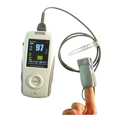
Henry Schein MD300K2 User manual

Henry Schein
Henry Schein Maxima 900-3510 User manual
