Heyl Testomat EVO TH Operating instructions

1
Testomat® EVO TH
Service Instructions
These operating instructions are the copyrighted property of Heyl Analysen-
technik GmbH & Co. KG.
It is intended for customer service and should only be used by authorised ser-
vice staff.
No part of this publication may be reproduced or transmitted in any form or by
any means to a third party, in particular to our competitors, without express
prior permission of Heyl Analysentechnik GmbH & Co. KG.

Contents
2
Contents
Contents...............................................................................................2
Important safety information .............................................................3
Qualification of the staff ........................................................................3
Warning notices in these instructions ...................................................3
Further documents................................................................................4
General instructions...........................................................................4
Key combinations when switching on...................................................6
Prior to carrying out maintenance work ................................................7
Permissible tools...................................................................................7
Carrying out maintenance..................................................................8
Removing and installing the measuring chamber holder......................8
Cleaning of clogged solenoid valves ....................................................9
Repairing or replacing the dosing pump.............................................13
Replacing the dosing pump valves.....................................................14
Checking the dosing pump .................................................................14
Checking dosing .................................................................................15
Special function “Adjust mode”......................................................16
Testing of the overflow detection........................................................16
Checking the automatic adjustment....................................................17
Manual measured value check........................................................18
Troubleshooting................................................................................19
Error message “36 Fault analysis” ......................................................19
Error message “38 Water low” ............................................................21
Error message “33 Fault optics”..........................................................22
Error message “34 Fault turbid” ..........................................................22
Error due to defective hardware .........................................................22
Readjusting the current interface........................................................23
Spare parts for Testomat®EVO TH .................................................24
Component positions.......................................................................25
Checklist Testomat®EVO TH.............................................................29

Important safety information
3
Important safety information
Please read the operating instructions and maintenance instruc-
tions carefully and completely prior to carrying out maintenance
work at Testomat instruments.
Observe the warning notices in these maintenance instructions
and the operating instructions of the respective instrument.
Always adhere to hazard warnings and safety tips when using
reagents, chemicals and cleaning agents. Please adhere to the re-
spective safety data sheet! Download the safety data sheets for
the supplied reagents at http://www.heyl.de.
Qualification of the staff
Maintenance work requires fundamental electrical and process engi-
neering knowledge as well as knowledge of the respective technical
terms. Assembly and commissioning should therefore only be carried
out by a specialist or by an authorised individual supervised by a
specialist.
A specialist is someone who due to his/her technical training, know-
how and experience as well as knowledge of relevant regulations can
assess assigned tasks, recognise potential hazards and ensure ap-
propriate safety measures. A specialist should always adhere to the
relevant technical regulations.
Warning notices in these instructions
The warning notices in these instructions warn the user about poten-
tial dangers to individuals and property resulting from incorrect han-
dling of the instrument. The warning notices are structured as follows:
Description of the type or source of danger
Description of the consequences resulting from non-observance
Preventive measures. Always adhere to these preventive
measures.
“DANGER” indicates an immediate hazardous situation which, if not
avoided, will result in death or serious injury.
“WARNING” indicates a potentially hazardous situation which, if not
avoided, could result in death or serious injury.
“CAUTION” indicates a potentially hazardous situation which, if not
avoided, could result in minor or moderate injuries or property dam-
age.
“NOTE” indicates important information. If this information is not ob-
served, it may result in an undesirable result or state.
DANGER
!
WARNING
!
CAUTION
!
SIGNAL WORD!
NOTE

General instructions
4
Further documents
Testomat instruments are plant components. Therefore, always ob-
serve the documentation of the plant manufacturer.
General instructions
Regular maintenance is necessary to ensure trouble-free operation of
the Testomat instrument. Regular visual inspections also increase
operational reliability. Also refer to the notes in the operating instruc-
tions!
Fix errors by yourself.
Experience has shown that many errors that occur in day-to-day op-
erations you can fix by yourself.
This ensures that the instrument is soon working again. In this
maintenance manual you will find possible causes of malfunctions
and helpful hints for their elimination.
Overview of maintenance work to be executed
The maintenance intervals may vary depending on the water and
pipeline quality.
Maintenance work
Quarterly
Semi-
annually
Annually
Biennially /
Triennially
Cleaning sight-glass windows
X
Cleaning measuring chamber / measur-
ing chamber holder
X
Cleaning the receiver optics
X
Cleaning the controller/filter housing
X
Cleaning the waste water line
X
Checking the dosing pump incl. suction
and pressure hoses
X
Electrical and hydraulic connections
X
Renewing the sealing kit (40124) and
sight-glass windows
X
Recommendation:
Allow the manufacturer to overhaul the
dosing pump
X
NOTE

General instructions
5
•Clean the measuring chamber at regular intervals (approx. every 6
months) and, if possible, replace the two seals of the measuring
chamber holder and the sight-glass windows.
•If the water has high iron content, cleaning might be necessary
more often.
•Only use a dry, lint-free cloth for cleaning.
•To carry out maintenance work after the error message “35 Fault
soiling” or “33.Fault optics”, always confirm the error message.
•If maintenance is carried out after an instrument maintenance
message (maintenance interval), maintenance must be confirmed.
BASIC PROGRAM -> SERVICE TIME -> ACKNOWLEDGE
•Wait at least 5 seconds before switching the instrument on and
then off again at the main switch.
•A defective device, regardless of the guarantee period, can be
serviced only when the device is dismantled and the error is de-
scribed. Please also inform us of the indicator type currently in use
and the measured medium. Make no changes or modifications to
the device that go beyond the scope of use specified in these in-
structions. Doing so will void the warranty. This applies particularly
to the measuring chamber, the seal of which must remain undam-
aged. If you send the device in for repair, please completely empty
the measuring chamber and remove the indicator bottle and the
drain funnel. Also remove the power pack and send it back in the
original packaging.
Before dismantling, the type of error must be noted (error number,
error effect, log file of the SD card).
•Once a protective device has been triggered (safety fuse), initially
try resolving the cause of error (e.g. by replacing a defective
valve), before reactivating the protective device. Frequent trigger-
ing always signifies an error, which under certain circumstances
may also damage the device.
•Before sending the device in for maintenance or repair, pack-
age the power pack individually in the original box in which it
was delivered. If the original packaging is no longer available,
package the power pack to prevent breakage.

General instructions
6
Key combinations when switching on
You can gain access to some service functions when you press a key
or a combination of keys when switching on the device. The following
table gives you an overview of the possible combinations.
Key
Function
Calibration mode
Basic programming
Skip automatic venting
Factory settings, SD format, empty/fill
measuring chamber, pumps, etc.
Caution! The SD card will be deleted.
Show operating hours
Test program
Set up language
Password reset
Demo mode
Import/export customer data. If there is no
export file, the export will take place. If there
is data, the import will take place

General instructions
7
Prior to carrying out maintenance work
Carry out a visual inspection of the instrument:
•Are the instrument doors closed properly?
•Is the instrument heavily soiled?
•Is there air inside the dosing hoses?
•Are the hose connections of the dosing pump free of leaks?
•Has the use-by date of the indicator expired?
Always make sure that the sight-glass windows are clean before in-
serting a new indicator bottle.
Cleaning agents
Never use organic solvents to clean the measuring chamber or
other plastic parts!
Use an acidic cleaning agent for cleaning.
Please observe the safety regulations when handling cleaning
agents!
Permissible tools
Only use suitable tools for the work described, e.g., our tool set
T2000 (Art. No. 40138) and our maintenance case T2000 (Art. No.
270338) with all necessary spare parts for regular maintenance.
Content of the tool kit T2000 (Art. no. 40138)
Size
Application
Art. no.
Torx, TX 20x100
Measuring chamber, snap-on installa-
tion
30991
Torx, TX 10x80
Measuring chamber holder
30992
Torx, TX 8x60
Display circuit board , measuring
chamber holder
30993
CAUTION
!

Carrying out maintenance
8
Carrying out maintenance
This service manual describes maintenance work that goes beyond
the regular maintenance work described in the “Maintenance and
repairs” chapter of the operating manual.
see Operating manual
- Replacing the indicator Page 66
- Setting the indicator level Page 67
- Cleaning the measuring chamber and the viewing
window Page 67
- Cleaning the filter housing Page 67
- Replacing the buffer battery Page 68
- Replacing the fuses Page 69
Removing and installing the measuring chamber
holder
(Required tool: Torx 10)
Stop the water supply to the instrument.
Drain the measuring chamber.
Switch off the instrument.
Unhook the toggle type fastener.
Tilt the measuring chamber upwards and remove it.
Remove the stirring bar.
Loosen the pressure hose .
Loosen the four fastening screws of the measuring chamber holder
.
Loosen the valve block from the measuring chamber holder
(two fastening screws).
Disconnect the plug from the flexible cable connection on the
base circuit board by pressing together and raising the two lateral
levers.
Unplug the flexible cable.
Remove the measuring chamber holder from the front. To achieve
this, remove the drain pipe from the hose connection of the
measuring chamber holder (see fig. push locking ring upwards).
Install the new measuring chamber holder in reverse order.
Ensure that the plug is locked into position after inserting the flexi-
ble cable connection.
Push locking
ring upwards
A

Carrying out maintenance
9
Cleaning of clogged solenoid valves
When the solenoid valve is clogged with impurities, the measuring
chamber is not properly emptied. In this case, the solenoid valve can
be carefully cleaned.
For dismantling all Testomat devices, please proceed as follows:
Switch off the device and disconnect it from the power supply.
Shut off the water supply in the supply line to the Testomat device.
Open the lower door.
Loosen the hose from the plug connector
Loosen the 4 cable connectors from the coils of the solenoid
valve.
Loosen the 2 screws that hold the solenoid valve in the housing.
(Torx 10)
Remove the solenoid valve forwards out of the housing.
To clean the solenoid valve, disassemble each side separately as
follows:
Start with the outlet side. On this side, the membrane of the valve
core may get stuck in the drill hole when the valve is contaminated.
The problem can be resolved mostly by loosening the membrane and
cleaning the drill hole.
Slide the retaining clip upwards from the anchor sleeve. To facil-
itate loosening, the upper lug can be lifted carefully using a screw-
driver.
Pull off the coil
Unscrew the anchor sleeve (SW 13)
Loosen the two screws of the metal plate on the valve body and
remove the anchor sleeve .
Carefully pull out the anchor with the spring from the anchor
sleeve. Ensure that the anchor is not released.
If the membrane does not come loose and the valve core cannot
be extracted, blow compressed air into the hole so that the mem-
brane comes loose.
When you blow compressed air through the valve, make sure that
the O-ring is not lost from the drill hole to the measuring cham-
ber. Therefore, remove the O-ring before every cleaning operation.
Blow in compressed air here

Carrying out maintenance
10
When microbial contamination or deposits are present, clean the
valve chamber and the parts of the valve with a small brush
(e.g. from our cleaning brush set, Art. No. 32287).

Carrying out maintenance
11
Use of cleaning agents
Never use organic solvents to clean the measuring chamber and
other plastic parts!
For cleaning, use an acidic cleaning agent.
Observe the safety instructions when handling cleaning agents!
Carry out assembly by following the steps for dismantling of the
same in reverse.
Make sure that you place the coil the right way round on to the an-
chor sleeve, as shown in the image above. The coil can be easily
placed on to the anchor sleeve in only one direction.
Now disassemble the inlet side in the same way, as described for
the outlet side.
Clean the inlet side, as described above.
After cleaning, reassemble all parts.
Additional cleaning instructions
Procedure in the event of corrosion:
Temporarily place the tie rod in a metal cleaning solution (no longer
than 5 minutes, depending on the concentration). Subsequently, neu-
tralise with plenty of clear water.
Under no circumstances must sandpaper be used!
It is far better to use metal-free cleaning fleece, e.g. from the compa-
ny Rothenberger
Procedure in the event of crystalline deposits:
Place the tie rod in either vinegar essence, pre-dissolved granulated
citric acid, or some limescale remover. In this case also, allow it to
take effect for no longer than 5 minutes. Subsequently, neutralise
with plenty of clear water, and, where appropriate, rework using met-
al-free cleaning fleece.
Prior to assembly:
Please wet the parts in direct contact with the medium with a fine
water-repellent silicone grease or spray, e.g. Baysilone
It is resistant to water vapour, sulphur dioxide, dilute acids and alka-
lis, and also is physiologically indifferent, skin-friendly and has excel-
lent dielectric properties.
When all of these instructions are implemented, older valves will also
work again properly for a long time.
CAUTION
!

Carrying out maintenance
12
Risk of interchanging parts
Do not interchange the inlet and outlet sides when mounting! The
springs are not identical. The solenoid valve no longer works when it
is incorrectly assembled.
Do not interchange the cable connectors of the inlet and outlet sides
when reconnecting (inlet: yellow-green cable; outlet: brown-white
cable). If necessary, take a photo prior to removal.
Ensure that the drill hole appears in the solenoid valve to the
measuring chamber.
Do not attempt to forcibly install the solenoid valve. If there are prob-
lems, check whether the solenoid valve has been properly assembled
and screw on to the measuring chamber using the correct side.
Reconstruct the solenoid valve by following the steps for disman-
tling of the same in reverse.
NOTE

Carrying out maintenance
13
Repairing or replacing the dosing pump
Maintenance rate
The dosing pump DOSIClip®is a high-precision piston dosing pump,
which makes up to 400 000 pump strokes per year depending on the
settings (a measurement all 10 minutes x 4 pump strokes every day).
To ensure proper operation for many years, we recommend sending
in the pump for servicing every 2-3 years.
Calibration on-site not possible!
We would like to point out that a repair of the dosing pump should be
performed only marginally, because calibration of the dosing pump
on-site is not possible.
We recommend exchanging a defective pump and sending it in for
servicing to the factory.
A pump which does not function properly results in incorrectly meas-
ured values (e.g. error message "36 Fault Analysis"). If you have
problems with the dosing pump, we recommend replacing it.
Proceed as follows to replace it:
1. Switch off the instrument.
2. Loosen the five cables of the terminal connections using a
suitable screwdriver.
3. Loosen the hose connections at the indicator bottle and at
the measuring chamber holder.
4. Collect the indicator in a container!
5. Use a screwdriver to push the lock of the pump housing
downwards and remove the housing from the top
6. At first, place the replacement pump on top of the DIN rail
and push the housing downwards until the lock engages
7. Reconnect the cables (observe the colour sequence!)
8. Reconnect the hose connections (note the suction and pres-
sure side!)
CAUTION
!
NOTE
Carrying out maintenance
14
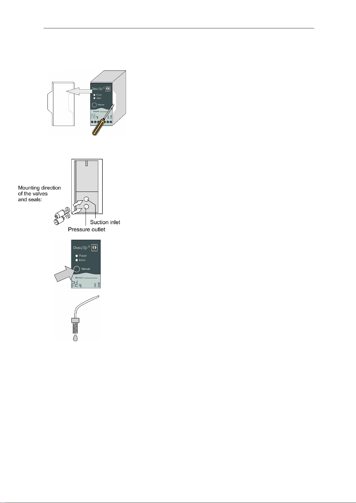
Replacing the dosing pump valves
In certain cases and with an obvious cause of malfunctioning, it is
also possible to replace the pump valves. Please proceed as follows:
1. Remove the transparent cover.
2. Use a suitable screwdriver to remove the electronics from the
housing (snap-on installation).
3. Replace the hoses or valves (observe the direction of instal-
lation.
4. Re-assemble the pump in reverse order. Please make sure
that wires and hoses are not trapped.
Checking the dosing pump
Proceed as follows to check correct functioning and the dosing quan-
tity of the dosing pump:
Press the “PAUSE” key
“PAUSE” LED illuminates.
Make sure that the measuring chamber is empty.
Remove the pressure hose from the measuring chamber holder.
Subsequently press the "manual" key on the dosing pump.
The dosing quantity must be a single drop (30 μl) and should drip
from the pressure hose
Collect the indicator in a container!
2.
1.
3.

Carrying out maintenance
15
Checking dosing
When measuring the hardness, it is checked whether the yellow val-
ue is at least 50 below the limit value after each (except the first)
dosing stroke. Each stroke usually results in the value being reduced
by 80 to 100 digits.
Manually activate the dosing pump once (see page15).
In “Adjust mode”, display the yellow value under “G:####”.
It is essential that the stirrer is switched on during the checking pro-
cedure.
Checks can only be carried out with indicator type TH!
The limit values are as follows (for exact adjustment to 900):
The limit values are as follows (for adjustment to 900 +- 20 digits):
The following table shows an adjustment example:
Stroke
Yellow LED
0
900 (= clear water)
1
809
2
726
3
662
4
609
5
566
6
531
7
500
8
477
9
457
10
441
11
427
12
416
13
405
14
393
15
385
NOTE

Special function “Adjust mode”
16
Special function “Adjust mode”
The adjust mode is used for testing the overflow detection and the
optical amplification setting.
The amplification setting is carried out in the normal measuring mode
of the instrument, i.e. manual adjustment is not required. The test
described below is only used for checking and error detection.
Call of adjust mode
Press and hold the key and switch on the instrument.
Back to measuring mode
Press the and keys simultaneously.
Testing of the overflow detection
Press the key to open the input valve IN.
The “IN” LED illuminates.
The “ANALYSIS” LED must illuminate when the water flows
through the overflow borehole of the measuring chamber If this
does not occur, check the water intake (incoming water), the view-
ing window (contamination) and the flexfilm (plug, corrosion).
Press the key to open the output valve OUT.
The “OUT” LED illuminates.
NOTE

17
Checking the automatic adjustment
Prior to adjustment, fill the measuring chamber with deionised wa-
ter (VE water) until overflow occurs.
Switch to “Adjust mode” (see “Calling adjust mode”).
Press the key to switch on the transmit diodes and the stir-
ring mechanism.
Press the key to start automatic adjustment.
Read the values for yellow (Y:) and red (R:). Both values have to
be 900 +/- 20.
If these values are not achieved, it may be due to the following rea-
sons:
•The water is turbid.
•Air bubbles in the water.
•The measuring chamber is not filled correctly.
•The sight-glass windows are soiled or cracked.
•The receiver optics (lenses) is soiled.
•The plug connector of the flexible cable is not locked (loose con-
tact).
•The measuring chamber holder is leaky, entered water has de-
stroyed the electronics on the circuit board.
Press the “Manual” button on the dosing pump.
A colour change must take place in the measuring chamber (see
also “Checking dosing” on Page 14).

Manual measured value check
18
Manual measured value check
The measured value check of the Testomat instruments is usually
carried out during a laboratory analysis of the measuring water. In
special cases, this check can also be carried out via direct input of a
standard solution, created especially for this task, into the measuring
chamber.
Creating a standard solution
The standard solution must be created on-site for rapid application.
For example, take a 1000 ppm solution and dilute it until you
achieve the desired value in the upper third of the measuring
range.
Manual supply of the standard solution
Please stop the water supply to the instrument.
Please remove the right-hand plug from the measuring chamber.
The measuring chamber is manually filled with the standard solu-
tion via this borehole after starting the measurement. Common la-
boratory spray bottles can be used for this task.
To start the check, activate the measurement via the key.
Testomat starts with an analysis cycle. If you have programmed a
flushing time, do not fill the measuring chamber until the output
valve has closed (“OUT” LED extinguishes).
Fill the measuring chamber with the standard solution until it over-
flows. The input valve closes (“IN” LED extinguishes). This solution
is then drained (flushing the measuring chamber).
Once the output valve has closed ("OUT” LED extinguishes), refill
the measuring chamber with the standard solution until it over-
flows. The filling level falls to the intended sample volume.
The measured value is displayed once the analysis has finished.
Valve
block
NOTE

Troubleshooting
19
Troubleshooting
In this section, you will find the most common error messages, possi-
ble causes and how to resolve them.
A complete table with all error messages, possible causes and trou-
bleshooting measures can be found from Page 58 onwards in the
Operating manual.
Error message “36 Fault analysis”
A measuring fault analysis occurs when the water in the measuring
chamber is too “light” after the second dosing.
Check the following points if “36 Fault analysis”is displayed:
1. The indicator’s expiry date has been exceeded.
Remedy:
There is insufficient dye in the indicator. Use a new indicator.
When using an indicator that is not from Gebr. Heyl, replace it with
the one recommended by us.
2. The stirring bar in the measuring chamber holder fails to
rotate, resulting in an insufficiently mixed indicator.
Remedy:
The stirring bar is stuck due to soiling in the stirring area of the
measuring chamber holder. Clean the measuring chamber.
The measuring chamber holder is leaky, entered water has de-
stroyed the electronics on the circuit board. Change the measuring
chamber holder.
The plug connector of the flexible cable is not locked (loose con-
tact). Insert the plug properly into the socket.
The magnet in the stirring bar is too weak. Change the stirring bar.
If necessary, insert a stirring bar.
Check the plug contact of the flexible printed circuit board. If nec-
essary, replace the measuring chamber holder.
3. The pump doses insufficient indicator.
Remedy:
Check the dosing pump (see “Checking the dosing pump”). If nec-
essary, replace the dosing pump.
Check pump dosing (see “Checking dosing”). If necessary, replace
the dosing pump.
4. Air is trapped in the indicator hose.
Remedy:
Bleed the dosing hoses by pressing the “Manual” button on the
dosing pump several times.

Troubleshooting
20
Make sure that all the indicator hoses are fitted correctly. If not, air
may enter the hoses!
If the error re-occurs, replace the bottle insert for a screw cap with
a suction tube (art. no.: 40135).
Make sure that the suction and pressure hose set is not kinked or
trapped. If necessary, replace the hoses. Complete suction hose
(art. no. 40011), complete pressure hose (art. no. 40016).
5. The water pressure is insufficient. Water is supplied, but the
water level inside the measuring chamber remains too high
after closing the inlet valve.
Remedy:
The water level should be approx. 32 mm above the lower edge of
the transparent measuring chamber block.
Make sure that the water pressure is within the valid range of 0.3 -
1 bar (without valve body) and 1 - 8 bar (with valve body).
Make sure all the dummy plugs are in place at the measuring
chamber (e.g. after maintenance). Make sure all the dummy plugs
are fitted correctly, thus preventing air leaks.
6. The drain pipe is blocked. Water may collect and stand in the
pipe.
Remedy:
Make sure the water outlet is not blocked. If necessary, clean it.
7. The measuring chamber is soiled.
Remedy:
All the channels in the measuring chamber and the measuring
chamber sight-glass windows must be free of indicator residue or
any other type of contamination.
Dirt can be removed with either ethyl alcohol or another commer-
cially available plastic cleaner.
Also clean the receiver optics.
8. The measuring water must be completely free of bubbles
when carrying out measurements and should not have a
milky appearance.
Remedy:
Make sure there are neither air bubbles nor more than 20 mg/l CO2
in the measuring water.
Air bubbles or milky measuring water may be the result of incorrect
regeneration of the softening plant or residual salt in the soft water.
Use our aerator R (art. no. 130010).
Table of contents
Other Heyl Measuring Instrument manuals

Heyl
Heyl Testomat Modul TH Operating instructions

Heyl
Heyl Testomat 2000 THCL User manual

Heyl
Heyl Testomat NH2CL User manual

Heyl
Heyl Testomat EVO User manual

Heyl
Heyl Testomat NH2CL-R User manual

Heyl
Heyl Testomat 2000 Cr VI 0 - 5 ppm User manual

Heyl
Heyl Testomat 808 Series Manual

Heyl
Heyl Testomat EVO TH series User manual

Heyl
Heyl Testomat 808 User manual

Heyl
Heyl Testomat ECO User manual


