HID OMNIKEY 5553 User manual

15370 Barranca Parkway
Irvine, CA 92618-2215
OMNIKEY®
Multi-ISO (HID5553) RFID Reader
USER MANUAL
© 2005-2011 HID Global Corporation. All rights reserved.
1508-USM-00-0-04
Firmware Version 1.2.5
May 2011
Doc Number: 1508-USM-00, Rev E.0

1508-USM-00-0-05 HF Multi ISO RFID Reader User Manual, Firmware V1.2.5
Warning - Read before start-up!
The product may only be used for the intended purpose designed by the manufacturer. The
operation manual should be conveniently kept available at all times for each user.
Unauthorized changes that have not been sold or recommended by the manufacturer may have a
negative influence on the system the program has been installed or copied on. Such unauthorized
measures shall exclude any liability by the manufacturer.
The liability-prescriptions of the manufacturer in the issue valid at the time of purchase are valid for
the device. The manufacturer shall not be held legally responsible for inaccuracies, errors, or
omissions in the manual or automatically set parameters for a device or for an incorrect application
of a device.
Only qualified personnel should carry out installation, operation, and maintenance procedures.
Use of the program and its installation must be in accordance with national legal requirements.
When working on devices the valid safety regulations must be observed.
Read Me First
About this Guide
This manual describes the HF Multi ISO Reader. Its goal is to describe the reader, how it works,
how to integrate it and how to use it.
Contacts
North America
15370 Barranca Parkway
Irvine, CA 92618
USA
Phone: 800 237 7769
Fax: 949 732 2120
Asia Pacific
19/F 625 King’s Road
North Point, Island East
Hong Kong
Phone: 852 3160 9800
Fax: 852 3160 4809
Europe, Middle East & Africa
Phoenix Road
Haverhill, Suffolk CB9 7AE
England
Phone: +44 1440 714 850
Fax: +44 1440 714 840
support.hidglobal.com
HID GLOBAL, HID, the HID logo, and OMNIKEY are the trademarks or registered trademarks of HID
Global Corporation, or its licensors, in the U.S. and other countries.
Page 2 of 132 May 2011
© 2005-2011 HID Global Corporation. All rights reserved.

HF Multi ISO RFID Reader User Manual, Firmware V1.2.5 1508-USM-00-0-05
Contents
Scope .........................................................................................................................................................7
Overview ......................................................................................................................................................8
Definitions ........................................................................................................................................ 8
References....................................................................................................................................... 8
Abbreviations ................................................................................................................................... 8
Supported Tags.............................................................................................................................. 10
15553 Reader Core – Multi ISO.....................................................................................................12
1.1 Dimensions .............................................................................................................................. 12
1.2 Jumper 1 Details...................................................................................................................... 13
1.3 Jumper 2 Details...................................................................................................................... 14
1.4 External Connections .............................................................................................................. 15
1.4.1 Power Supply ...........................................................................................................................15
1.4.2 Antenna....................................................................................................................................16
1.4.3 Serial Interface .........................................................................................................................17
1.4.4 Function Control LEDs .............................................................................................................17
1.4.5 SAM Connector/Socket ............................................................................................................18
2Software........................................................................................................................................19
2.1 Transmission Protocol ............................................................................................................. 19
2.1.1 ASCII Protocol..........................................................................................................................19
2.1.2 Binary Protocol .........................................................................................................................20
2.2 Register Set............................................................................................................................. 22
2.2.1 EEPROM Memory Organization...............................................................................................22
2.2.2 Unique Device ID (00h – 04h) ..................................................................................................23
2.2.3 Station ID (0Ah)........................................................................................................................23
2.2.4 Protocol Configuration 1 (0Bh) .................................................................................................23
2.2.5 BAUD, Baud Rate Control Register (0Ch)................................................................................26
2.2.6 Command Guard Time (0Dh) ...................................................................................................27
2.2.7 OPMODE - Operating Mode Register (0Eh).............................................................................27
2.2.8 Single Shot Time-Out (0Fh)......................................................................................................27
2.2.9 TMR, RF Time-Out Control Register (10h, 11h).......................................................................27
2.2.10 Type B framing Register (12h) .................................................................................................28
2.2.11 Protocol Configuration 2 (13h)..................................................................................................28
2.2.12 Reset Off Time (14h) ................................................................................................................29
2.2.13 Reset Recovery Time (15h)......................................................................................................29
2.2.14 Application Family Identifier (16h) ............................................................................................29
2.2.15 Selection Time-Out ISO 14443A (17h) .....................................................................................30
2.2.16 Selection Time-Out ISO 14443B (18h) .....................................................................................30
2.2.17 Selection Time-Out SR176 (19h) .............................................................................................30
2.2.18 Selection Time-Out ISO 15693 (1Ah).......................................................................................30
2.2.19 Protocol Configuration 3 (1Bh) .................................................................................................30
2.2.20 Modulation Conductance 0 (1Dh).............................................................................................31
2.2.21 Threshold (1Eh)........................................................................................................................31
2.2.22 Protocol Configuration 4 (20h)..................................................................................................32
2.2.23 CID (21h)..................................................................................................................................32
May 2011 Page 3 of 132
© 2005-2011 HID Global Corporation. All rights reserved.

1508-USM-00-0-05 HF Multi ISO RFID Reader User Manual, Firmware V1.2.5
2.2.24 RxWait (22h) ............................................................................................................................33
2.2.25 Modulation conductance 1 (23h) ..............................................................................................33
2.2.26 Modulation conductance 2 (24h) ..............................................................................................33
2.2.27 Modulation conductance 3 (25h) ..............................................................................................33
2.2.28 User data (80h - EFh)...............................................................................................................33
2.3 Command Set.......................................................................................................................... 34
2.3.1 Common Command Details .....................................................................................................36
2.3.2 ISO 14443 Type A (MIFARE®) only commands .......................................................................64
2.3.3 Key Management .....................................................................................................................69
2.3.4 my-d™ secure ..........................................................................................................................77
2.3.5 ‘t’ Command – Data Frame Transfer ........................................................................................83
2.3.6 ‘t’ command block format & examples......................................................................................87
2.3.7 ‘e’ command – SAM data frame transfer ..................................................................................90
2.3.8 ‘e’ command block....................................................................................................................95
2.3.9 EMVCo Commands..................................................................................................................96
3Frequently Asked Questions ....................................................................................................100
3.1 Getting Started ...................................................................................................................... 100
3.2 Personalizing Multi ISO Reader ............................................................................................ 100
3.3 MIFARE Card Type ............................................................................................................... 101
3.4 MIFARE ................................................................................................................................. 101
3.5 Using NFC ............................................................................................................................. 103
4Supported Tags..........................................................................................................................104
4.1 MIFARE Transponder Family ................................................................................................ 104
4.1.1 MIFARE Standard ..................................................................................................................104
4.1.2 MIFARE Ultralight...................................................................................................................106
4.1.3 MIFARE Ultralight C ...............................................................................................................106
4.1.4 MIFARE 4k .............................................................................................................................106
4.1.5 MIFARE Prox .........................................................................................................................106
4.1.6 MIFARE DESFire ...................................................................................................................107
4.1.7 my-d™ IC (SLE 55Rxx) .......................................................................................................... 110
4.2 ISO 14443 Type B ................................................................................................................. 111
4.2.1 SR176 ....................................................................................................................................111
4.2.2 SRIX4K...................................................................................................................................112
4.3 ISO 15693.............................................................................................................................. 112
4.3.1 Coding of UID.........................................................................................................................112
4.3.2 Memory organization..............................................................................................................113
4.3.3 my-d™ IC (SRF55VxxP) ........................................................................................................113
4.3.4 EM 4135 .................................................................................................................................114
4.4 ICODE ................................................................................................................................... 115
4.4.1 Memory organization..............................................................................................................115
4.4.2 Serial number .........................................................................................................................115
4.4.3 Write access condition............................................................................................................115
4.4.4 Special function (EAS,) AFI....................................................................................................115
4.4.5 User data................................................................................................................................115
4.5 ICODE EPC........................................................................................................................... 116
4.5.1 Memory organization..............................................................................................................116
4.5.2 Serial number .........................................................................................................................116
4.5.3 Read Block .............................................................................................................................116
4.5.4 Write Block .............................................................................................................................116
Page 4 of 132 May 2011
© 2005-2011 HID Global Corporation. All rights reserved.

HF Multi ISO RFID Reader User Manual, Firmware V1.2.5 1508-USM-00-0-05
4.6 ICODE UID ............................................................................................................................ 116
4.6.1 Memory organization..............................................................................................................116
4.6.2 Read Block .............................................................................................................................116
4.6.3 Write Block .............................................................................................................................116
Appendix A - References........................................................................................................................117
Appendix B - SAM Socket Details .........................................................................................................118
Appendix C - Timings.............................................................................................................................119
Appendix D - 5553 Reader Board RS232 Compact MultiISO..............................................................121
(0701800160)............................................................................................................................... 121
Appendix E - Document Version History..............................................................................................128
Appendix F - Firmware Revision History..............................................................................................129
Functional Changes ..................................................................................................................... 129
Bug Fixes ..................................................................................................................................... 129
Appendix G - Approvals / Certificates ..................................................................................................130
CE Declaration ............................................................................................................................. 130
FCC Declaration........................................................................................................................... 130
RoHS Compliance........................................................................................................................ 131
Appendix H - EMC Compliance (Radiated Emissions)........................................................................132
List of Figures
Figure 1 - Reader Core - Top View............................................................................................................. 12
Figure 2 - Power Supply Option 1............................................................................................................... 15
Figure 3 - Power Supply Option 2............................................................................................................... 16
Figure 4 - Typical Antenna Tuning.............................................................................................................. 16
Figure 5 - OEM Board Serial Interface........................................................................................................ 17
Figure 6- Connecting External LEDs - Option 1.......................................................................................... 17
Figure 7 - Connecting External LEDs - Option 2........................................................................................ 17
Figure 8 - SAM Connector .......................................................................................................................... 18
Figure 9 - KTT State Diagram..................................................................................................................... 81
Figure 10 - State Diagram......................................................................................................................... 105
Figure 11 - DESFire Memory .................................................................................................................... 107
Figure 12 - DESFire State Diagram .......................................................................................................... 108
Figure 13 - 5553 Reader RS232 Compact Multi ISO - Top View ............................................................. 122
Figure 14 - 5553 Reader RS232 Compact Multi ISO - Side View ............................................................ 123
Figure 15 - 5553 Reader RS232 Compact Multi ISO - Front View ........................................................... 123
Figure 16 - Pin Out – Jumper 3................................................................................................................. 123
Figure 17 - RS232 Configuration - Jumper 3 Pin Out............................................................................... 124
Figure 18 - RS422 Configuration - Jumper 3 Pin Out............................................................................... 125
Figure 19 - RS485 Configuration - Jumper 3 Pin Out............................................................................... 126
Figure 20 - Jumper 4 Pin Out - Top View ................................................................................................. 126
May 2011 Page 5 of 132
© 2005-2011 HID Global Corporation. All rights reserved.

1508-USM-00-0-05 HF Multi ISO RFID Reader User Manual, Firmware V1.2.5
Figure 21 - Jumper 4 Pin Out.................................................................................................................... 127
List of Tables
Table 1 - Pin out – Jumper 1....................................................................................................................... 13
Table 2 - Electrical characteristics of J1 PINs............................................................................................. 13
Table 3 - Pin out – Jumper 2....................................................................................................................... 14
Table 4 - Electrical characteristics of J2 PINs............................................................................................. 14
Table 5 - Common Command Overview..................................................................................................... 34
Table 6 - Card Specific Commands ............................................................................................................ 35
Table 7 - Error Codes.................................................................................................................................. 35
Table 8 - Register Type with Corresponding Register................................................................................ 53
Table 9 - Sending Serial Data Frame ......................................................................................................... 56
Table 10 - Receiving Serial Data Frame..................................................................................................... 57
Table 11 - Version 1 (Option Byte) ............................................................................................................. 91
Table 12 - Version 2 (Option Byte) ............................................................................................................. 92
Table 13 - EMVCo Mode – Test Command Set ......................................................................................... 98
Table 14 - Timings .................................................................................................................................... 119
Table 15 - Pin out – Jumper 3 Detail ........................................................................................................ 124
Table 16 - J3 pins in RS232 Configuration - Electrical Characteristics .................................................... 124
Table 17 - J3 pins in RS422 Configuration - Electrical Characteristics .................................................... 125
Table 18 - J3 pins in RS485 Configuration - Electrical Characteristics .................................................... 126
Table 19 - J4 pins - Electrical Characteristics........................................................................................... 127
Page 6 of 132 May 2011
© 2005-2011 HID Global Corporation. All rights reserved.

HF Multi ISO RFID Reader User Manual, Firmware V1.2.5 1508-USM-00-0-05
Scope
The HID HF Multi ISO Reader Module supports a broad range of tags compliant with ISO 14443
type A and B standards, including SR176 tags, tags which belong to the NXP MIFARE family, ISO
15693 tags, ISO 18000-3, EPC and UID tags. An open command structure allows the device to
communicate with tags that use an operating system. The read/write unit supports ISO 14443-4
layer with automatic chaining, 256 byte buffer and frame length, extended time framing and up to
848kBaud transmission rates over the air interface.
Several protocols are available to enable the reader module to be connected to a variety of
equipment. The ASCII protocol facilitates the use of a simple terminal; the Binary protocol provides
robust communication more suitable for a dedicated host system. If a host computer is used, then a
function library is available, providing function calls rather than low-level ‘byte-bashing’.
For the SAM interface security features and DESFire credential DES encryption, the function library
provides access to these features in the Reader Module. The function library is available for
Windows CE and XP host applications.
Major applications are:
Access control, identification using security credentials
Ticketing using standard MIFARE and DESFire credentials
May 2011 Page 7 of 132
© 2005-2011 HID Global Corporation. All rights reserved.

1508-USM-00-0-05 HF Multi ISO RFID Reader User Manual, Firmware V1.2.5
Overview
Definitions
Anti-collision loop
An algorithm used to identify and handle a dialogue between a reader and one or more tags in its
antenna field.
ASCII notation
ASCII characters are listed within apostrophes, i.e. ‘x’ means a single x.
Hex notation
A hexadecimal value is marked with the suffix ‘h’, i.e. A1h has the value A1 hexadecimal.
References
See AN0311 for the Firmware Update Procedure.
Abbreviations
Abbreviation Description
AID Application ID
ASCII American Standard Code for Information Interchange
ATR Answer to Reset
ATS Answer to Select
AFI Application Family Identifier
Block For the MIFARE Standard one block contains 16 bytes
CBC Cipher Block Chaining
CID Card Identifier (logical card address, ISO 14443-4)
CRC Cyclic Redundancy Check
DES Data Encryption Standard, for more details about DES refer to [3].
DSFID Data storage format identifier
EDC Error Detection Code
EGT Extra Guard Time
EOF End of Frame
ETU Elementary time unit
Hex / xxh Value in Hexadecimal notation
I-block Information block
KTT Key Transfer Transponder
LSB Least Significant Bit or Byte
MSB Most Significant Bit or Byte
NAD Node Address (ISO 14443-4)
OSI Open System Interconnection
OTP One time programmable
PCB Protocol Control Byte (ISO 14443-4)
Page 8 of 132 May 2011
© 2005-2011 HID Global Corporation. All rights reserved.

HF Multi ISO RFID Reader User Manual, Firmware V1.2.5 1508-USM-00-0-05
May 2011 Page 9 of 132
© 2005-2011 HID Global Corporation. All rights reserved.
Abbreviation Description
PCON Protocol Configuration byte of the reader
PPS Protocol and Parameter Selection
RATS Request for Answer to Select
R-block Receive ready block
REQA Request ISO Type A
REQB Request ISO Type B
RFU Reserved for Future Use
S-block Supervisory block
SAM Secure Application Module
Sector For the MIFARE Standard one sector contains 4 blocks
SID Station ID
SFGT Guard time after RATS
SN Serial Number of a tag (a 32 bit number)
SOF Start of frame
TDES Triple DES
Value block 32 bit data block format. Used in ticketing application
<CR> Carriage return (0Dh)
<LF> Line feed (0Ah)

1508-USM-00-0-05 HF Multi ISO RFID Reader User Manual, Firmware V1.2.5
Supported Tags
For tag details see Supported Tags, page 104.
Tag
Manufacturer
Serial number
Read/Write operation
Transfer command
Comments
ISO 14443 A
MIFARE Standard NXP
MIFARE 4k NXP
MIFARE Ultralight NXP Disable Read-After-Write
(see 2.2.22.1)
MIFARE Ultralight C NXP
Disable Read-After-Write
(see 2.2.22.1)
Read/Write commands for unprotected
pages only
MIFARE ProX NXP
MIFARE DESFire NXP -
MIFARE Plus NXP
Read/Write/Login commands in
MIFARE-Classic mode only
(Security Level 1)
MIFARE Mini NXP
SLE66CLX320P Infineon
- encryption not included
SLE 55R04 / 08 Infineon - encryption included
Smart MX NXP -
Jewel Innovision
Topaz Innovision
ISO 14443 B
SLE6666CL160S Infineon
-
SR176 STM
SLIX 4K STM
ASK GTML2 ISO ASK -
ASK GTML ASK - extended setup needed
Sharp B Sharp -
Page 10 of 132 May 2011
© 2005-2011 HID Global Corporation. All rights reserved.

HF Multi ISO RFID Reader User Manual, Firmware V1.2.5 1508-USM-00-0-05
May 2011 Page 11 of 132
© 2005-2011 HID Global Corporation. All rights reserved.
Tag
Manufacturer
Serial number
Read/Write operation
Transfer command
Comments
TOSMART P0032/64 Toshiba -
Dual Interface
ISO 14443 A
compliant1
various -
ISO 14443 B
compliant2
various -
ISO 15693
EM 4135 EM
ICode® SLI NXP
LRI12 STM
LRI64 STM
with 10% modulation index
LRI128 STM
LRI2k STM
better performance with 10%
modulation index
SRF55VxxP Infineon
SRF55VxxS Infineon
encryption included
Tag-it™ HF-I Std TI
Tag-it™ HF-I Pro TI - - only in addressed mode
TempSense KSW
- Temperature logging
ICode
ICode® NXP
ICode® EPC NXP
ICode® UID NXP
1Performance varies
2Performance varies
1508-USM-00-0-05 HF Multi ISO RFID Reader User Manual, Firmware V1.2.5
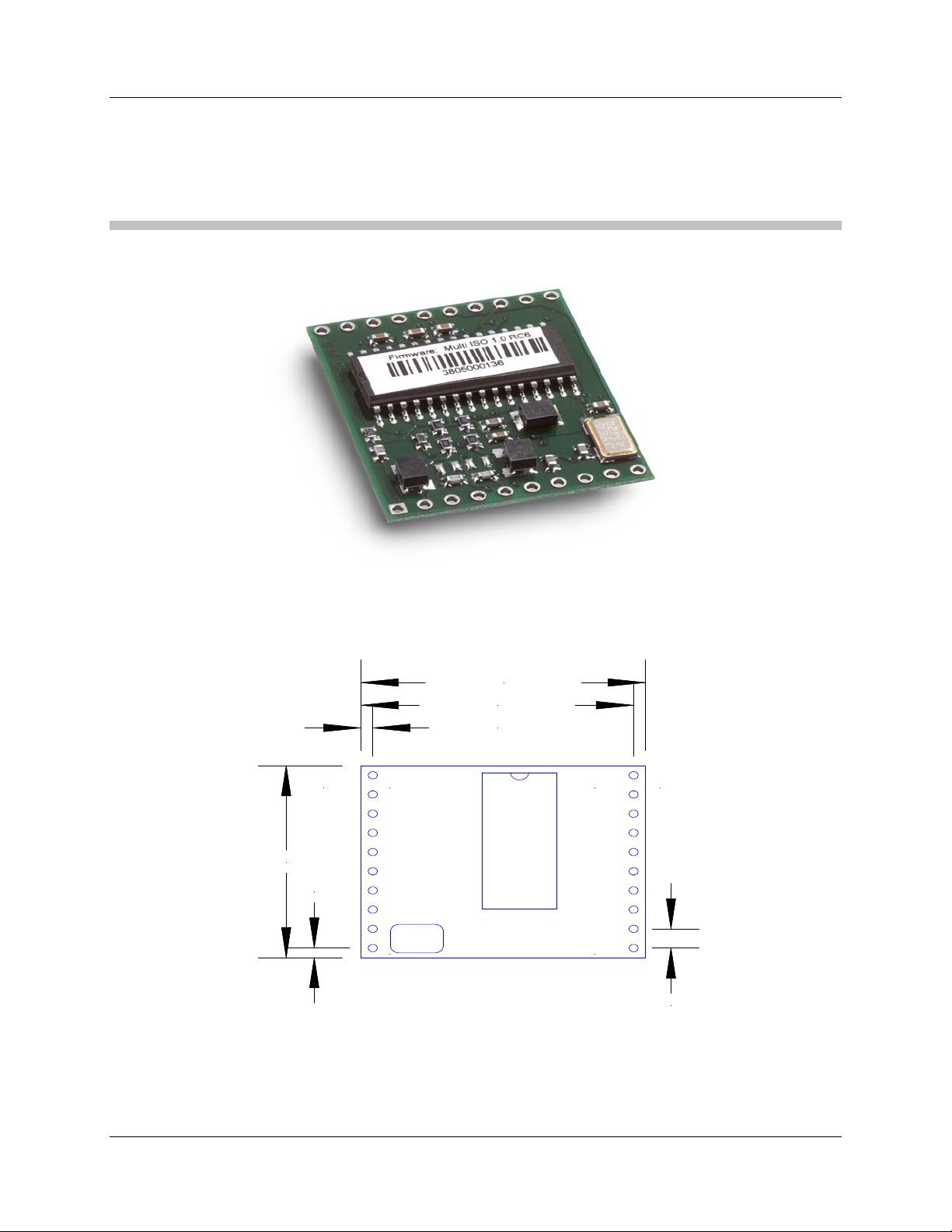
15553 Reader Core – Multi ISO
1.1 Dimensions
All dimensions listed in millimeters.
1
10 11
20J1 J2
2,54 mm
1,27 mm
29,21 mm
30,48 mm
1,27 mm
25,40 mm
Figure 1 - Reader Core - Top View
Page 12 of 132 May 2011
© 2005-2011 HID Global Corporation. All rights reserved.

HF Multi ISO RFID Reader User Manual, Firmware V1.2.5 1508-USM-00-0-05
1.2 Jumper 1 Details
Table 1 - Pin out – Jumper 1
PIN PIN No. Description
ARX 1 Antenna RX
ATX1 2 Antenna TX1
VDD 3 Supply Voltage
GND 4 Ground
ATX2 5 Antenna TX2
TGND 6 Antenna Ground
SAM CLK 7 SAM clock
SAM IO 8 SAM IO
SAM RESET 9 SAM Reset
RTS 10 Request to Send
Table 2 - Electrical characteristics of J1 PINs
PIN PIN No. Min Typ. Max. Description
ARX 1 1.1V 4.4V pk-pk Antenna RX
ATX1 2 13,56 MHz
34 VPP
13.56MHz
100 mAPP
50VPP
Antenna TX1
+4.5V +5.0V +5.5V Supply VoltageVDD 3
32mA 150mA 250mA Supply Current (without SAM)
GND 4 GND Ground
ATX2 5 13,56 MHz
34 VPP
13.56MHz
100 mAPP
50VPP
Antenna TX2
TGND 6 GND Antenna Ground
TTL
25mA
SAM CLK 7
3,39MHz
SAM clock
SAM IO 8 TTL 25 mA IO for SAM Input and SAM
Output
SAM RESET 9 TTL 25 mA SAM Reset
RTS 10 TTL 25 mA Request to Send
May 2011 Page 13 of 132
© 2005-2011 HID Global Corporation. All rights reserved.
1508-USM-00-0-05 HF Multi ISO RFID Reader User Manual, Firmware V1.2.5
Page 14 of 132 May 2011
© 2005-2011 HID Global Corporation. All rights reserved.
1.3 Jumper 2 Details
Table 3 - Pin out – Jumper 2
PIN PIN No. Description
VDD 20 Supply Voltage
GND 19 Ground
LEDg 18 LED green (reading LED)
LEDr 17 LED red
EN 16 Enable reader, open or logic high
MCLR 15 Master clear
USER 14 User Port
DIR 13 Direction of RS 485
TX 12 TX to PC
RX 11 RX from PC
Table 4 - Electrical characteristics of J2 PINs
PIN PIN No. Min Typ. Max. Description
RX 11 USART-TTL125 mA Rx to PC
To RS232, RS485 or RS422 device
driver
TX 12 USART-TTL125 mA Tx to PC
To RS232, RS485 or RS422 device
driver
DIR 13 TTL 25 mA Direction of RS 485
Logic High = Reader to Host
Logic Low = Host to Reader
USER 14 TTL325 mA User Port
MCLR 15 TTL4Master clear
Leave unconnected
EN 16 ST525 mA Enable reader
logic low will disable the reader
Open or logic high
VDDmin
@ 25mA
VDDtyp
@ 11mA
VDDmax
@ 0 mA
LED red
Output Voltage
LEDr 17
11mA 25mA External Resistor
min. 200
1Universal Synchronous Asynchronous Receiver Transmitter
3TTL buffer output / input. If user port is used as an output, a 1kΩ(current limiting) series resistor
has to be integrated into the connecting wire, otherwise the reader device can be damaged.
4Voltage spikes below GND at the MCLR/VDD pin, including currents greater than 80mA, may
cause latch-up. Thus, a series resistor of 50-100should be used when applying a "low" level to
the MCLR/VDD, rather than pulling this pin directly to GND.
5Schmitt trigger buffer input
HF Multi ISO RFID Reader User Manual, Firmware V1.2.5 1508-USM-00-0-05
May 2011 Page 15 of 132
© 2005-2011 HID Global Corporation. All rights reserved.
PIN PIN No. Min Typ. Max. Description
1.4V
@ 11mA
VDD
@ 0mA
LED green (reading LED)
with 330 (internal serial) resistor
LEDg 18
11mA 15mA
GND 19 GND Ground
VDD 20 +4.5V +5.0V +5.5V Supply Voltage
IDD 32 mA 150 mA 250 mA Supply Current (Without SAM)
1.4 External Connections
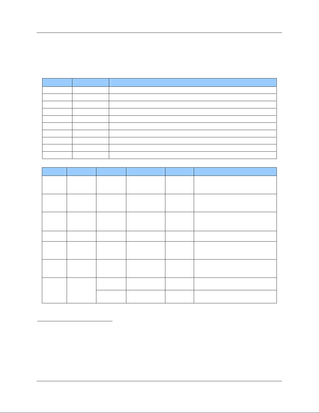
1.4.1 Power Supply
If the supply voltage and any noise modulated on the supply voltage remains within the specified
limits, no further filtering is required. In some cases it is recommended to use additional filtering for
the power supply line. Insufficient power line filtering could cause unexpected or irregular
performance drops.
uC
20
19
OEM Board
+5V DC
Figure 2 - Power Supply Option 1
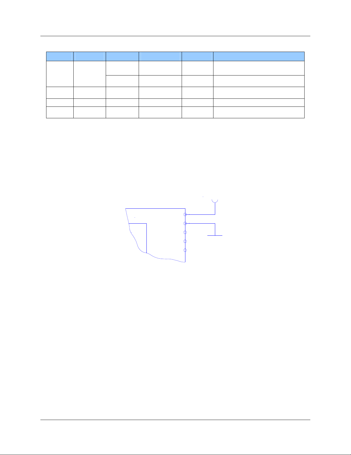
1508-USM-00-0-05 HF Multi ISO RFID Reader User Manual, Firmware V1.2.5
The board can be connected as shown in Figure 3 - Power Supply Option 2. Both alternatives are
possible and can be used as they fit best into the layout of the carrier board. The two VCC PINs and
the two GND PINs are connected internally.
3
4
OEM Board
+5V DC
Figure 3 - Power Supply Option 2
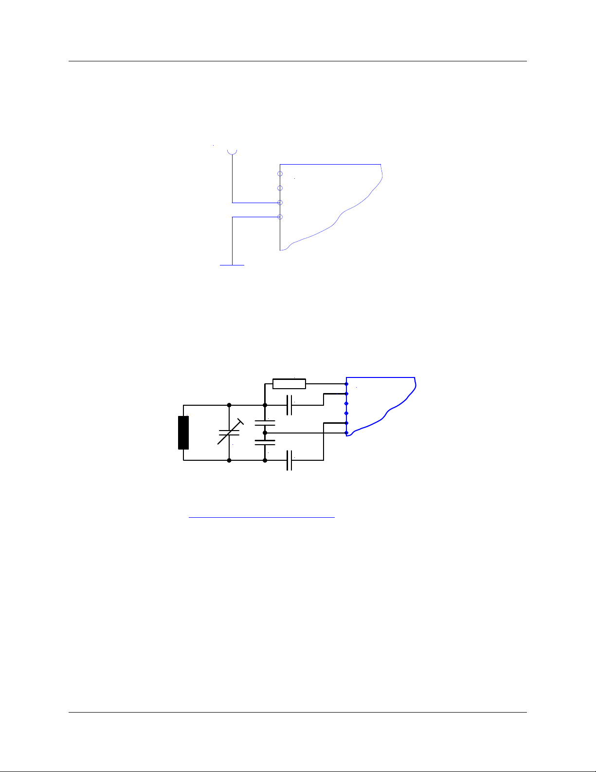
1.4.2 Antenna
The typical antenna tuning and matching network is shown in Figure 4 - Typical Antenna Tuning.
The external antenna has to have the right inductance and a certain resistor and capacitor
combination for an optimized frequency tuning and antenna matching.
6
5
1
2OEM Board
C1
C2
C3
C4
C5
L ANT
R1
Figure 4 - Typical Antenna Tuning
More details about the antenna design are available in the HID Antenna Design guide. Download
this document from http://www.hidglobal.com/Omnikey.
Reference the specific application notes for the NXP reader IC (MIFARE & I-Code, Micore Reader
IC family Directly Matched Antenna Design).
Page 16 of 132 May 2011
© 2005-2011 HID Global Corporation. All rights reserved.

HF Multi ISO RFID Reader User Manual, Firmware V1.2.5 1508-USM-00-0-05
1.4.3 Serial Interface
The OEM Board can be connected directly with a micro controller. Alternatively the OEM Board also
can be connected to most serial interface types by using the right interface converter circuit. In
order to optimize the communication quality the specific application note of the interface converter
circuit needs to be taken into consideration.
12
11
Interface
Converter
Circuit
Host Interface
OEM Board
Figure 5 - OEM Board Serial Interface
1.4.4 Function Control LEDs
Two external LEDs can be connected to the OEM Board. There are two alternatives possible.
uC 18
17
OEM Board
330 Ohm
Figure 6- Connecting External LEDs - Option 1
uC 18
17
330 Ohm
OEM Board
330 Ohm
Figure 7 - Connecting External LEDs - Option 2
In both cases the LED supply voltage levels are TTL levels.
May 2011 Page 17 of 132
© 2005-2011 HID Global Corporation. All rights reserved.

1508-USM-00-0-05 HF Multi ISO RFID Reader User Manual, Firmware V1.2.5
1.4.5 SAM Connector/Socket
Note: The power supply to the SAM must be turned off during the entire SAM insertion/withdrawal
period; otherwise damage to the SAM may occur.
When using a SAM with the OEM board, it is recommended that a 100nF decoupling capacitor be
fitted between Vcc and GND close to the SAM socket to ensure proper operation. The complete
circuit diagram is shown in Figure 8 - SAM Connector.
7OEM Board
8
9
SAM
Module
Vcc
GND
CLK
I/O
RST
100nF
Figure 8 - SAM Connector
PIN-outs for 8 Pin SAM Socket and 6 Pin SAM Socket is shown in Appendix B.
Note: The SAM interface hardware does not support error repetition and does not check the parity
bit.
Page 18 of 132 May 2011
© 2005-2011 HID Global Corporation. All rights reserved.

HF Multi ISO RFID Reader User Manual, Firmware V1.2.5 1508-USM-00-0-05
2Software
In order to offer the widest possible choice of interface, the MultiISO reader offers both ASCII and
Binary serial protocols – see Transmission Protocol, page 19.
EEPROM registers in the reader hold default settings for Station ID, protocol, serial and air-speed
settings, timing parameters and modulation index – listed in Register Set, page 22. These registers
are alterable using the Read/Write EEPROM commands detailed in Command Set page 34. The
register settings are applied to the reader through the configuration registers.
These configuration registers may be altered ‘on-the-fly’ to immediately affect performance by the
‘set configuration flag/register’ commands, but the changes are lost once the reader is powered
down, unless also written into the EEPROM registers. These and all other configurable settings are
detailed in the Register Set – Register Set, page 22.
General reader commands are listed in Command Set page 34 and detailed in Common Command
Details, page 36, dealing with the physical attributes of the reader – reset, LED control, User port
control, Antenna power – and the basic tag commands – include/exclude tag types, continuous
read, tag select and air speed select, and simple block read/write commands.
Tag-specific commands for MIFARE and My-D tags are listed in Sections ISO 14443 Type A
(MIFARE®) only commands, page 64 and my-d™ secure, page 77, and commands to manipulate
keys are listed in Key Management, page 69.
For more complex commands, the ‘t’ command is used. This uses a data frame or packet to
exchange information – see ‘t’ Command – Data Frame Transfer, page 83 and ‘t’ command block
format & examples, page 87 for examples of use
To communicate with the optional SAM, the ‘e’ command is used. This also encapsulates a data
frame/packet to exchange information, based on the ISO7816 APDU – see ‘e’ command – SAM
data frame transfer, page 90 and ‘e’ command block, page 95 for examples of use.
2.1 Transmission Protocol
Two protocol modes are supported, with the default held in the reader EEPROM. As factory default,
the ASCII protocol is used, and the default serial configuration is 9600baud, n, 8, 1, with no
handshaking.
2.1.1 ASCII Protocol
This protocol is designed for easy handling. The commands may be issued using a terminal
program, such as HyperTerminal, and the data is transmitted as ASCII hexadecimal that can be
easily displayed on the terminal program.
Command Data
Variable length Variable length
May 2011 Page 19 of 132
© 2005-2011 HID Global Corporation. All rights reserved.

1508-USM-00-0-05 HF Multi ISO RFID Reader User Manual, Firmware V1.2.5
2.1.2 Binary Protocol
This protocol is designed for industrial applications with synchronization and frame checking. An
addressing byte for party line (master/slave, multi-drop) is also included.
The protocol usually requires a device driver. Data is transmitted in binary mode. The reader uses
an internal binary watchdog timer to ensure correct framing.
STX Station ID Length Data BCC ETX
1 byte 1 byte 1 byte Variable length 1 byte 1 byte
The binary frame version 2 is only sent to the host. It is implemented to give extended information to
the host. Version 2 must be enabled in the Protocol configuration 2 register.
STX Station ID Length Flags Data BCC ETX
1 byte 1 byte 1 byte 1 byte Variable length 1 byte 1 byte
2.1.2.1 STX
Start of transmission (02h for data block sizes 1-256 bytes, 82h for data block sizes 257-512 bytes).
2.1.2.2 Station ID
Unique ID of the station
00h: Reserved for the bus master. Readers send response to this device ID.
FFh: Broadcast message. All devices will execute the command and send their response.
2.1.2.3 Length
Length defines the length of the data block (including the flag byte if binary protocol version 2 is
activated). If the STX character is 02h, the length field represents the actual data block length (1 to
256, with a length of 256 being represented by the value 0). If the STX character is 82h, the length
field should be added to 256 to obtain the block length (for example, 1 = data block length of 256+1,
2 = data block length of 256+2, 0 = data block length of 256+256).
2.1.2.4 Flags
The flag byte gives additional information to the host.
Bit 3 – Bit 7 Bit 1 – Bit 2 Bit 0
RFU Leading Character Info Error State
Error State
If cleared, the command was processed successfully. If set, an error occurred.
Leading Character Info
Bit 1 & 2 defines how to interpret the data in the binary frame.
Bit 2 Bit 1 Description
0 0 No leading character available, all values are hexadecimal.
0 1 The data contains one leading character.
1 0 All data bytes are characters.
1 1 RFU
Page 20 of 132 May 2011
© 2005-2011 HID Global Corporation. All rights reserved.
Table of contents
Other HID RFID System manuals


Popular RFID System manuals by other brands


turck
turck TN-UHF-Q MYS Series quick start guide

hager
hager XEVA265 installation manual

caenrfid
caenrfid Slate R1260U Technical information manual

Iron logic
Iron logic MATRIX-V PASSPORT AND INSTRUCTION ON CONNECTION AND OPERATION

caenrfid
caenrfid Lepton9 R9100C Technical information manual

ISAFE MOBILE
ISAFE MOBILE IS-MP.2 Quick start manual