manuals.online logo
Brands
  1. Home
  2. •
  3. Brands
  4. •
  5. HIK VISION
  6. •
  7. Security Sensor
  8. •
  9. HIK VISION DS-PDP18-HM User manual

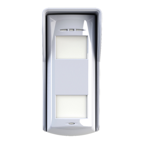
HIK VISION DS-PDP18-HM User manual

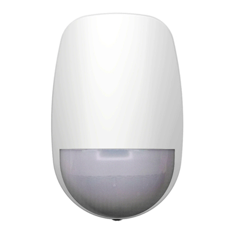
DS-PDP18-HM
Wired Double PIR Detector
User Manual
EN50131-2-2:2021
Security Grade 2
Environment Class IV
Hangzhou Hikvision Digital Technology CO.,Ltd. No.555 Qianmo Road, Binjiang District, Hangzhou 310052, China
UD33808B
User Manual Flow Chart
1 Appearance
2 Installation
Bracket Tamper
67.3 mm
141.6 mm
60.0 mm
Tamper Switch
LED Jumper
PIR Sensitivity Jumper
High and Low Mounting Adjustment Lever
H Model (default): 2.5 to 3 m (typical 2.7 m)
L Model: 0.8 to 1.2 m (typical 1 m)
LED OFF
Pet Immunity
LED ON (default)
Auto (default)
1.1 Unbox.
1.2 Check components.
Select the wiring type and
connect the detector to the
control panel.
2.1 Confirm environment.
2.2 Fix the device (Wall
mounting/Bracket mounting).
Check detection range
in H and L mode.
Check the indicator,
and the device is
powered on.
1 Appearance
3 Connect to
Control Panel
2 Installation
5 Detection Range
4 Power on
Installation Environment
Facing Direct
Strong Light
Source of
air currents
Facing reflective
surfaces
Areas with
moving objects
Surface that absorb heat or
rapid temperature change area
1Wall Mounting
2
13
1. Adjust the knob to the
unlock icon.
2. Press the button.
3. Remove the rear panel.
Wire Slot
4. Method 1 (Recommended):
Thread the cables through the
middle wire hole on the rear panel.
4
5
5. Fix the rear panel to the
corresponding position on the wall
with two screws. Remove the wiring
terminal and finish wiring.
Wire Terminal
6
6. Install the wiring terminal
back and fix the cables into
the wire slot.
7. Adjust the high and low
mounting adjustment lever,
and Install the front panel.
7
8. Adjust the knob to the lock icon.
8
Back of Wire hole
4
4. Method 2: Thread the
cables through the wire
hole on the rear panel.
2Bracket Mounting
1
4. Install the bracket to the wall.
6. Remove the bracket tamper
cover on the front panel.
7. Connect the tamper cable to the front
panel, and fix the cable into the wire slot.
8. Adjust the high and low mounting
adjustment lever, and install the front panel.
45
6
78
1. Adjust the knob to the
unlock icon.
2. Press the button.
3. Remove the rear panel.
5. Install the wiring terminal back and fix the
cables into the wire slot. Thread the tamper
cable through the wire hole, and fix the rear
panel to the bracket with one screw.
Wire Slot
9
9. Adjust the knob to the lock icon.
2
3
Wire Slot
=
=
=
=
3 Connect to Control Panel Note: The resistor needs to be connected to the end of detector.
1None Resistor Connection
Single EOL Connection
Double EOL Connection
Triple EOL Connection
Control Panel
Control Panel
Control Panel
Control Panel
Detector
Detector
Detector
Detector
ALARMTAMPER +-
EOL EOL
ALARMTAMPER +-
EOL EOL
ALARMTAMPER +-
EOL EOL
ALARMTAMPER +-
EOL EOL
ZONE1
ZONE1
ZONE1
ZONE2
ZONE2
ZONE2
COM
COM
COM
+ -
+ -
+ -
+ -
ZONE2ZONE1 COM
2
TAMPER/ALARM
Z
G
2.2 K
2.2 K
TAMPER/ALARM
Z
G
3
ALARMTAMPER
Z
G
2.2 K
2.2 K2.2 K
2.2 K
4
FAULT TAMPER ALARM
1 K
1 K1 K
2.2 K
2.2 K 1 K
Z
G
2.2 K
Alarm: 1K, 2K2, 4K7, 5K6, 6K8
Tamper: 1K, 2K2, 4K7, 5K6
=
4K7
2K2
1K
5K6
6K8
4K7
4K7
2K2
2K2
1K
1K
5K6
5K6
6K8
6K8
ALARM +
-
EOL
TAMPER
EOL
ALARM +
-
EOL
TAMPER
EOL
ALARM
TAMPER
4K7
4K7
2K2
2K2
1K
1K
5K6
5K6
For double and triple EOL connection, the detector has two method for resistor wiring:
(1) Use jumpers to select the End of Line resistance (Control panel dependent) on the ALARM/TAMPER pins.
(2) Select an resistance (Control panel dependent), and add the resistor to ALARM/TAMPER wiring ports of the detector.
Please select one resistor wiring method according to the figure below.
ALARM
ALARM
TAMPER
TAMPER
4K7
2K2
1K
5K6
2.2 K
1 K
FAULT
FAULT
FAULT
FAULT
4 Power on
After powering on, the indicator flashes rapidly. Once the detector self test
is completed, the LED indicator will go out until the detector detects movement.
NOT READY READY
6 Specification
Detection
performance
Detection method Passive Infrared
Detection range 18 m (16m EN certified)
Detection angle 90°
Detection zones 118
Detectable speed 0.3 to 2 m/s
Sensitivity Auto, Pet
White light filter 20000 lux
Pet immunity Up to 24 Kg
Digital temperature compensation Support
Feature
Digital processing Support
Sealed optics Support
Tamper protection Front, Rear
Software features End of line resistance Alarm: 1K, 2K2, 4K7, 5K6, 6K8
Tamper: 1K, 2K2, 4K7, 5K6
Hardware features Alarm output Normally Closed
Interface LED Blue (Alarm), Orange (Fault)
Electrical
characteristics
Power supply 9 to 16 VDC
Typical voltage 12 VDC
Power consumption Maximum current: 15 mA @12 VDC
Quiescent current: 8 mA@12 VDC
General
Operation temperature -25 °C to 70 °C (-13 °F to 158 °F)
Storage temperature -25 °C to 70 °C (-13 °F to 158 °F)
Operation humidity 10% to 90%
IP rate IP65
Dimension (W x H x D) 67.3 × 142.0 × 60.0 mm
Weight 226.3 g
Mounting height 2.5 to 3 m High Mount
0.8 to 1.2 m Low Mount
Mounting method Wall
Application scenario Indoor, Outdoor
5 Detection Range
Top View
Side View
High Mounting
Low Mounting
4m
8m
12m
16m
0m 0 4m8m 4m 8m 12m12m
2.7m
2m
1m
0m
16m14m12m10m2m 4m 6m 8m
3m
1m
0m
1.2m
16m14m12m10m2m 4m 6m 8m

Other HIK VISION Security Sensor manuals

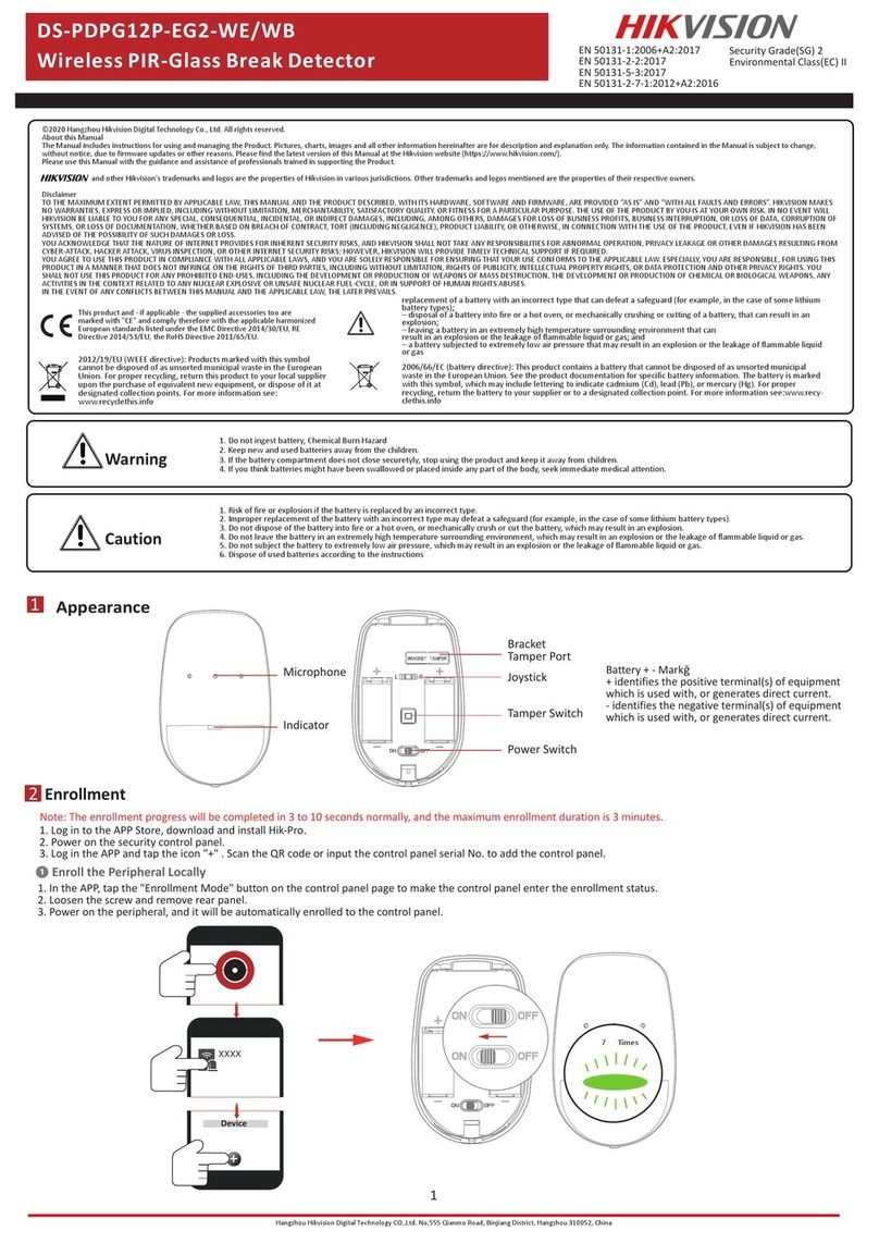
HIK VISION DS-PDPG12P-EG2-WB User manual

HIK VISION

HIK VISION DS-PDPG12P-EG2-WB User manual

HIK VISION DS-PDMCK-EG2-WB User manual

HIK VISION

HIK VISION DS-PDMCK-EG2-WB User manual

HIK VISION DS-PDPC12PF-EG2-WB User manual
HIK VISION

HIK VISION DS-PDPC12PF-EG2-WB User manual

HIK VISION DS-PDP15P-EG2 User manual

HIK VISION

HIK VISION DS-PDP15P-EG2 User manual

HIK VISION AX PRO Series User manual

HIK VISION

HIK VISION AX PRO Series User manual

HIK VISION DS-PDTT15AM-LM-WA User manual

HIK VISION

HIK VISION DS-PDTT15AM-LM-WA User manual

HIK VISION DS-PD2-T10P-WEH1 User manual

HIK VISION

HIK VISION DS-PD2-T10P-WEH1 User manual

HIK VISION DS-PDC10DM-EG2-WE User manual

HIK VISION

HIK VISION DS-PDC10DM-EG2-WE User manual

HIK VISION DS-PDCL12DT-EG2 User manual

HIK VISION

HIK VISION DS-PDCL12DT-EG2 User manual

HIK VISION DS-PDMCS-EG2-WB User manual

HIK VISION

HIK VISION DS-PDMCS-EG2-WB User manual

HIK VISION DS-PD2-P15C-W User manual

HIK VISION

HIK VISION DS-PD2-P15C-W User manual

HIK VISION DS-PD2-P25-W User manual

HIK VISION

HIK VISION DS-PD2-P25-W User manual

HIK VISION DS-PDMC-EG2-WE User manual

HIK VISION

HIK VISION DS-PDMC-EG2-WE User manual

HIK VISION DS-PD1-WL-W User manual

HIK VISION

HIK VISION DS-PD1-WL-W User manual

HIK VISION DS-PDBG12-EG2-WB User manual

HIK VISION

HIK VISION DS-PDBG12-EG2-WB User manual

HIK VISION DS-PDMCX-E-WB User manual

HIK VISION

HIK VISION DS-PDMCX-E-WB User manual
HIK VISION DS-PD2-P15C-W User manual

HIK VISION

HIK VISION DS-PD2-P15C-W User manual

HIK VISION DS-PD2-T10P-WEH User manual

HIK VISION

HIK VISION DS-PD2-T10P-WEH User manual

HIK VISION DS-PDMC-EG2-WB User manual

HIK VISION

HIK VISION DS-PDMC-EG2-WB User manual

HIK VISION DS-PD2-T12P-WEL User manual

HIK VISION

HIK VISION DS-PD2-T12P-WEL User manual

HIK VISION DS-PDC10AM-EG2-WE User manual

HIK VISION

HIK VISION DS-PDC10AM-EG2-WE User manual

HIK VISION DS-PDCO-E-WB User manual

HIK VISION

HIK VISION DS-PDCO-E-WB User manual

HIK VISION DS-PDP18-EG2 User manual

HIK VISION

HIK VISION DS-PDP18-EG2 User manual

HIK VISION DS-PDPG12P-EG2-WB User manual

HIK VISION

HIK VISION DS-PDPG12P-EG2-WB User manual

Popular Security Sensor manuals by other brands

Bosch VMD01 M50 PAL operating instructions

Bosch

Bosch VMD01 M50 PAL operating instructions

Bosch TriTech+ Professional ISC-PDL1-WAC30G installation instructions

Bosch

Bosch TriTech+ Professional ISC-PDL1-WAC30G installation instructions

jablotron JA-88P manual

jablotron

jablotron JA-88P manual

Agilent Technologies 5973N Hardware installation

Agilent Technologies

Agilent Technologies 5973N Hardware installation

SICK Prime KTX-WP91341252ZZZZ manual

SICK

SICK Prime KTX-WP91341252ZZZZ manual

Varex Imaging 4343W manual

Varex Imaging

Varex Imaging 4343W manual

Qvis QPIR-REC-IP65 instructions

Qvis

Qvis QPIR-REC-IP65 instructions

Network Bird Avpoint P14 Instruction booklet

Network Bird

Network Bird Avpoint P14 Instruction booklet

MIIDEX LIGHTING Vision-EL 754933 Notice Instructions

MIIDEX LIGHTING

MIIDEX LIGHTING Vision-EL 754933 Notice Instructions

GEV TITAN MOBI 180 manual

GEV

GEV TITAN MOBI 180 manual

Chuango AID-420 user manual

Chuango

Chuango AID-420 user manual

LEGRAND EMOS G1190 manual

LEGRAND

LEGRAND EMOS G1190 manual

Reno A&E B Series Installation and operating instructions

Reno A&E

Reno A&E B Series Installation and operating instructions

IKAR HRA Series Instructions for the use and inspection records

IKAR

IKAR HRA Series Instructions for the use and inspection records

Endress+Hauser Nivotester FTL325N-**** Series Brief operating instructions

Endress+Hauser

Endress+Hauser Nivotester FTL325N-**** Series Brief operating instructions

ATI Technologies SR 48 manual

ATI Technologies

ATI Technologies SR 48 manual

PCB Piezotronics ICP W138A01/038CY003AC Installation and operating manual

PCB Piezotronics

PCB Piezotronics ICP W138A01/038CY003AC Installation and operating manual

GE Baker Hughes Reuter-Stokes Flame Tracker... Operation and maintenance manual

GE

GE Baker Hughes Reuter-Stokes Flame Tracker... Operation and maintenance manual

manuals.online logo
manuals.online logoBrands
  • About & Mission
  • Contact us
  • Privacy Policy
  • Terms and Conditions

Copyright 2025 Manuals.Online. All Rights Reserved.