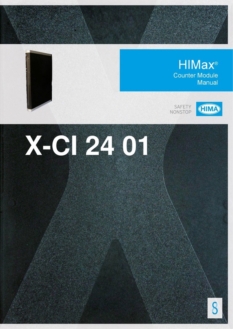
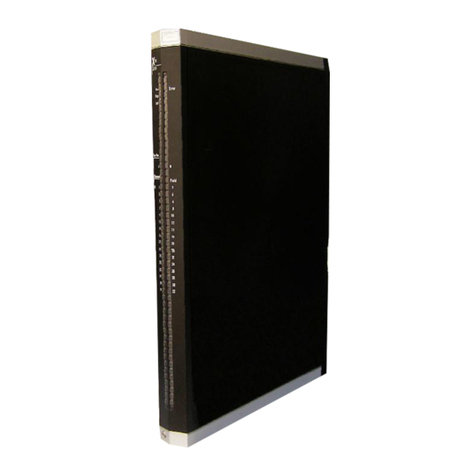
HIMA HIMax X-CI 24 51 User manual


Table of contents
Other HIMA Control Unit manuals
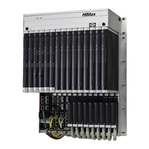
HIMA
HIMA HIMax X-COM 01 E User manual
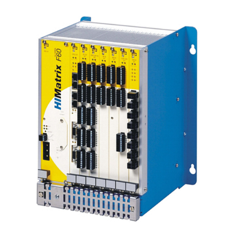
HIMA
HIMA HIMatrix F60 DI 32 01 User manual
HIMA
HIMA HIMax X-DI 64 51 User manual
HIMA
HIMA HIMax X-DI 32 52 User manual
HIMA
HIMA HIMax X-SB 01 User manual
HIMA
HIMA DIO 24/16 01 User manual
HIMA
HIMA HIMax X-DI 32 02 User manual

HIMA
HIMA HIMax X-DI 32 05 User manual
HIMA
HIMA HIMax X-MIO 7 01 User manual

HIMA
HIMA HIMax X-DO 32 51 User manual
Popular Control Unit manuals by other brands

Quectel
Quectel EG91 Series Hardware design

hyfire
hyfire TAURUS TAU-MI-S-01/NB quick start guide
Phytec
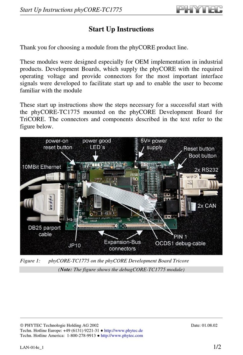
Phytec phyCORE-TC1775 Start-up instructions

Shenzhen Qianhai Lensen Technology
Shenzhen Qianhai Lensen Technology LS-U1000 user manual
Pentair
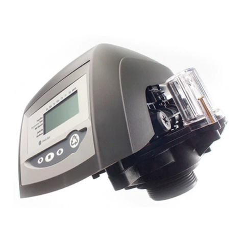
Pentair AUTOTROL 740 Service manual
Accutrol
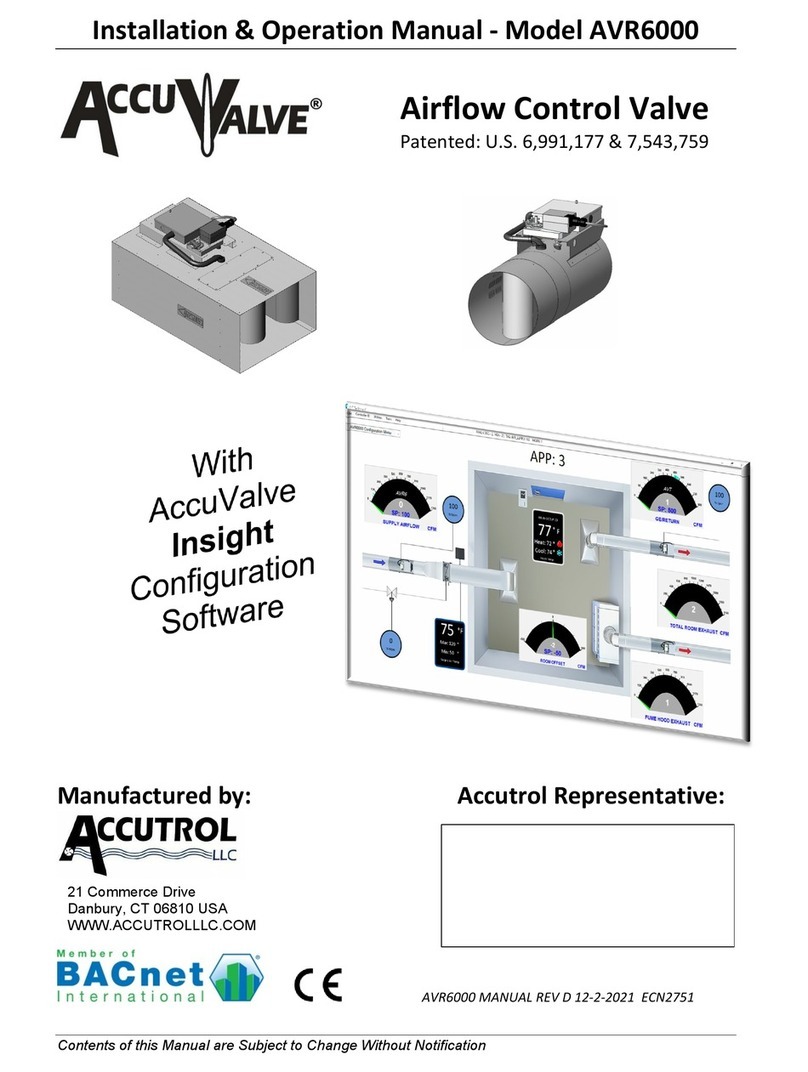
Accutrol AccuValve AVR6000 Installation & operation manual

Sistemes Electrònics Progrés s.a.
Sistemes Electrònics Progrés s.a. AGRONIC 4000 instruction manual

SBS Technologies
SBS Technologies VP7 Hardware user manual
ITRON
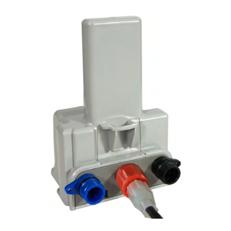
ITRON OpenWay Riva user manual
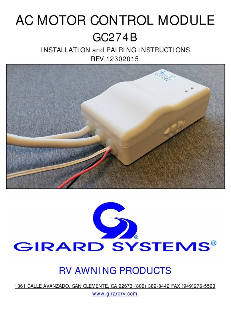
Girard Systems
Girard Systems GC274B installation instructions
Fairchild
Fairchild 74-13A instruction manual
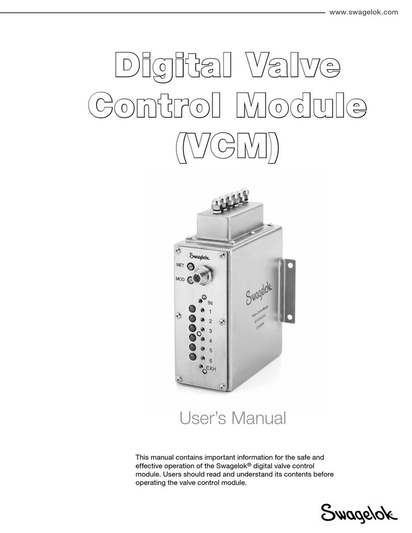
Swagelok
Swagelok VCM user manual
