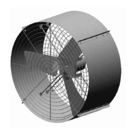
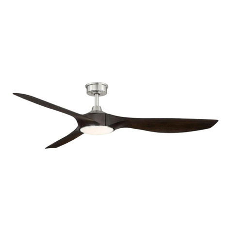
HIRED-HAND Funnel Flow 36 User manual

Part No. 4801-5401 Rev 6/07 Owners Manual 36" 48" & 52" Funnel Flow Fan - Unassembled
48
36" 48"&52"Funnel Flow Belt Drive Fan
Unassembled
Owner’sManual
Hired-Hand, Mfg., Inc.
PO Box 140
1733 County Road 68
Bremen, Alabama 35033

Part No. 4801-5401 Rev 6/07 36" 48" & 52" Funnel Flow Fan – Unassembled Page 2 of 12
1 Warnings Warning!
Disconnect All Power Sources Before Installing This Equipment. Failure To Disconnect Power Source
Can Result In Property Damage, Serious Injury Or Death!
Warning!
Dangerous Rotating Machinery! Keep Hands, Clothing, Etc. Clear When Operating!
Do Not Operate Without All Guards And Covers In Place!
Warning!
All Wiring Should Be In Accordance with National Electrical Codes Or Other Local Codes.
Warning!
The Installer Is Responsible For Complying With All Relevant Regulations, Such As National Wiring
Regulations And Accident Prevention Regulations. Particular Attention Must Be Given To The Cross-
sectional Areas Of Conductors, The Selection Of Fuses Or Other Protection, And Protective
Earth/Ground Connections!
Warning!
The Voltages In The Power Cables And Certain Parts Of The Drive Can Result In Death. Whenever The
Drive Has Been Used It Must Be Isolated And Disconnected For 5 Minutes Before Any Work Commences
Danger!
Only Qualified Electrical Personnel Familiar With The Construction And Operation Of This Equipment And
The Hazards Involved Should Install, Adjust, And/Or Service This Equipment. Read And Understand
This Manual In Its Entirety Before Proceeding. Failure To Observe This Precaution Could Result In
Severe Bodily Injury Or Death!
!
!
!
!
!
!
!
!
!

Part No. 4801-5401 Rev 6/07 36" 48" & 52" Funnel Flow Fan – Unassembled Page 3 of 12
2 Limited Warranty
All products are warranted to be free from defects in material and workmanship for a period of
one (1) year from the date of purchase if installed and used in strict accordance with the
installation instructions. Liability is limited to the sale price of any products proved to be
defective or, at manufacturer’s option, to the replacement of such products upon their return. No
products are to be returned to the manufacturer, until there is an inspection and/or a return-goods
authorization (RGA) number is issued.
All complaints should be directed first to the authorized distributor who sold the product. If
satisfaction is not obtained or the name of the distributor is not known, write the manufacturer
that appears below, directed to the attention of Customer Service Manager. All complaints should
be directed first to the authorized distributor who sold the product. If satisfaction is not obtained
or the name of the distributor is not known, write the manufacturer that appears below, directed to
the attention of Customer Service Manager.
This limited warranty is expressly in lieu of any and all representations and warranties expressed
or implied, including any implied warranty of merchantability or fitness for a particular purpose.
The remedy set forth in this limited warranty shall be the exclusive remedy available to any
person. No person has authority to bind the manufacturer to any representation or warranty other
than this limited warranty. The manufacturer shall not be liable for any consequential damages
resulting from the use of our products or caused by any defect, failure or malfunction of our
products. (Some areas do not allow the exclusion or limitation of incidental or consequential
damages, so the above limitation or exclusion may not apply to you).
This warranty gives you specific legal rights and you may also have other rights that vary from
area to area.
d you may also have other rights that vary from area to area.
Warrantor: Hired-Hand Mfg., Inc.
PO Box 140
1751 County Road 68
Bremen, Alabama 35033
Phone 256-287-7000

Part No. 4801-5401 Rev 6/07 36" 48" & 52" Funnel Flow Fan – Unassembled Page 4 of 12
3 Table of Contents
Section Description Page
1Warnings.....................................................................................................................................................2
2Limited Warranty.........................................................................................................................................3
3Table of Contents........................................................................................................................................4
4Funnel Flow Fan Mounting Instructions......................................................................................................4
5Tools Required............................................................................................................................................5
6Assembly Instructions.................................................................................................................................5
4 Funnel Flow Fan Framing Instructions
Framing Diagram
Fan Spacing with Cone
See Framing
Dimensions
Below
INTAKE
SIDE
EXHAUST
ORIFICE
SIDE
Fan Housing Cone
Center-to-Center
Spacing
Fan Size Spacing
36" 49.75" (126.4 cm)
48" 63.0" (160.0 cm)
52" 71.0" (180.3 cm)
Fan Size Fan Model Width Height
36" Funnel Flow 43.0" (109.2 cm) 43.0" (109.2 cm)
48" Funnel Flow 55.5" (139.7 cm) 55.5" (139.7 cm)
52" Funnel Flow 57.0" (144.8 cm) 57.75" (146.7 cm)
Height (H)
Rough Opening
Width (W)

Part No. 4801-5401 Rev 6/07 36" 48" & 52" Funnel Flow Fan – Unassembled Page 5 of 12
Detail A
Two washers on top
5 Tools Required
6 Assembly Instructions
6.1 Refer to Figure 1. Arrange the Top Brace and the Bottom
Brace as shown. Where the Braces join, line up the six
holes.
6.2 Refer to Figure 2. Locate the two pillow block bearings that
attach to the bottom of the bracket. Position each bearing
with the set screw to the outside. Align and center one
bearing with the bolt holes in the top front of bracket and the
other to the top rear. Refer to Detail A. Secure the bearing
mounts with four 5/16” x 1.5” (1004-5002) cap screws.
Insert one 3/8”stainless washer (1003-0106) and one 5/16”x
3/4"washer (1003-0103) on top of the bearing mount and
one 5/16” x 3/4” flat washer (1003-0103) from the bottom
and locknut (1001-0103) from the bottom. Do not tighten at
this time.
6.3 Tighten the two grease fittings with a 5/16“
socket.
6.4 Refer to Figures 3. Locate the Bearing Shaft
Alignment tool and place in the two center holes
over the drive shaft. The Head of the tool faces to
the rear of the Fan Brace. The tool serves to align
the bearing mounts. Tighten with ½” socket. If an
alignment tool is not available, see Detail C for
alignment measurements.
Tools Required: Torque Wrench
½” & 7/16” Wrenches Rubber Mallet
½”, 5/16” & 7/16” Sockets Lock-Tite Compound
4 mm Allen Head Socket Framing Square
5/32” Allen Head Socket 6” long 3/8” Extension
¼” &21/64”x5” Drill Bits ½” Drive (Ft-Lbs.)
3/8" Ratchet 3/8” Drive (In.-Lbs.)
3/8” Drill
IMPORTANT!
Locate packing slip and make sure that all
listed parts are enclosed. If not, call your
Hired-Hand distributor immediately. Please
read and understand all instructions in this
manual before assembling fan.
Figure 1
Figure 1
Front
Top Brace
48"&52"(0403-4889)
36"(0403-5520)
Bottom Brace
48"&52"(0403-4890)
36"(0403-5521)
Figure 2 Bearing
(
1016-0100
)
Set Screws face
outward
ad
Figure 3
Alignment
Tool -

Part No. 4801-5401 Rev 6/07 36" 48" & 52" Funnel Flow Fan – Unassembled Page 6 of 12
Figure 4
6.5 Refer to Figure 4. Slide the pulley 36”(1011-
2413) 48”&52”(1011-0100), on the bearing shaft
with the set screw to the bearing side as shown.
Place the key shear all the way into the key slot
and align the pulley to be flush with the end of
the shaft as shown in Figure 4. Tighten the
pulley set screw with a 4 mm Allen wrench to
110 inch pounds of torque.
6.6 Position the front of the pulley so that it touches the
Alignment tool as seen in Figure 5 and Detail B. (If
necessary, tap lightly on front of shaft with rubber
mallet).
6.7 Tighten the Allen (set) screws on the bearings to 70
inch pounds of torque. IMPORTANT: Use Lock-Tite
Compound. See Detail D.
Detail B
Figure 5
Detail D
Use Lock-Tite
Compound on
all set screws.
Pulley
Set
screw
Detail C
Prop Spider
(Blades not Shown)
1.625"
Shaft Flush
with Inside
of Hub
Shaft
Flush
with
Pulley
Hub
IMPORTANT
Detail B

Part No. 4801-5401 Rev 6/07 36" 48" & 52" Funnel Flow Fan – Unassembled Page 7 of 12
Figure 11
6.8 For a metal fan blade skip to Step 6.10. For a Fiberglass fan blade, place the Trans Torque Bushing
(1047-7001) over the front of the fan blade as shown in Figure 6. Then insert the fan blade onto the
bearing shaft flush and tighten with a 1½” socket to 94 foot pounds of torque as shown in Figure 7.
6.9 For a Standard Metal Prop refer to Figure 8.
Place the Blade Assembly flush with the shaft.
Tighten the bolt with a 9/16“ socket to 110 inch
pounds torque.
6.10 Refer to Figure 10. Place the Pulley Assembly
36”(1101-9003) 48&52” (1011-9005) in front of the
Tension Bracket 36”(0403-5522) 48&52”(0403-4891)
and fasten with 3/8” X 1” hex head bolt (1004-1426)
and hex head washer/screw (1004-6020). Tighten
the bolt with a 9/16 “ socket and the screw with a 3/8 “
socket.
6.11 Place the Pulley Assembly under the top brace as
shown in Figure 11 and attach with six 1/4” x 3/4” hex
head bolts (1004-5017), six 1/4” flat washers (1003-
0108) and lock nuts (1001-0104) using a 7/16“
socket.
Figure 7
Figure 10
Bolt
(1004-1426)
Set Screw
(1004-6020)
Figure 6
Trans Torque Bushing
Figure 9
Figure 8

Part No. 4801-5401 Rev 6/07 36" 48" & 52" Funnel Flow Fan – Unassembled Page 8 of 12
Figure 15
Figure 12
Figure 13 Alignment Jig
6.12 Now remove the Pulley Alignment tool from the
top brace and check the alignment of the
bearings. Straighten the bearing to be
perpendicular to the shaft and tighten securely.
6.13 Place the Bracket Assembly and place into the
Fiberglass shroud 36" (4003-3002) 48" (4003-
3003), 52" (4003-3001), as shown in Figure 12.
Note the two drainage holes at the bottom of
the shroud.
6.14 With the shroud lying flat on the floor, attach a
Fan Alignment Jig on the end of each blade as
shown in Figure 13. Now carefully spin the fan
and align the four bracket arms so that the fan
blade does not touch the shroud. This will
provide a 3/16” clearance between the fan blade
and the shroud. (Note: in some cases the
alignment tool may slightly touch the housing,
but should allow the fan to be rotated freely.)
6.15 While rotating the fan blade, the bracket arms
should be lined up so as to center into their
respective corners. See Figure 12.
6.15 Refer to Figure 15. Firmly hold the bracket arms in
position and drill a hole through the fiberglass shroud
using a 21/64“ drill bit (at least 5“ long) using the
hole in the side of the bracket arm as a guide.
Figure 14
Align arm to
point to
corner of
shroud.

Part No. 4801-5401 Rev 6/07 36" 48" & 52" Funnel Flow Fan – Unassembled Page 9 of 12
Motor
installation
holes
Figure 19
Figure 20
Figure 21
Push motor all
the way up the
brace.
6.16 Refer to Figure 16. Fasten arms to shroud with 5/16” x 7/8” hex head bolt (1004-5000) and
5/16” x 1½” fender washer (1003-2604) from the outside of the shroud. Use 5/16” x ¾” flat
washer (1003-0103) and lock nut (1001-0103) as shown.
6.17 Refer to Figure 17. NOTE: The 36” fan does not require a gusset. For the 48” & 52” fans, install the
gusset (0403-4892) using the proper mounting holes using 5/16" cap screw (1004-5000), two washers
(1003-0103) and lock nut (1001-0103). Level the gusset and drill four holes through the shroud.
Fasten the gusset to the top left corner of the cabinet using six ¼” cap screws (1004-5017), twelve
5/16” x ¾” flat washers (1003-0103), and six lock nuts (1001-0103).
6.18 Remove the three Fan Alignment Jigs placed on the ends
of the fan blades in Step 14.
6.19 Install the two Tension Latches (1040-0105) and Latch
plates (0403-6756) on either side of the shroud using 3/16”
rivets (1005-1469). See Figure 18.
6.20 At this point the fan housing can be installed in the wall
before completing the rest of the installation steps.
6.21 Install the motor in the top mounting holes as
shown in Figures 19, 20 and 21 using four
carriage bolts (1002-2818), and lock nuts (1001-
0103). Before tightening bolts, push the motor all
the way up the mounting arm to give the proper
tension on the belt.
Figure 16
Tension Latch
(1040-0105)
Figure 18
Figure 17
Drill four ¼” holes in shroud.
52” mount
48” mount

Part No. 4801-5401 Rev 6/07 36" 48" & 52" Funnel Flow Fan – Unassembled Page 10 of 12
Figure 22
Figure 23
Figure 24
Straight
Edge
should
touch
pulleys in
four
places.
6.22 Refer to Figure 22. Install the motor pulley with the set
screw facing outward. Install the shaft key (1019-2417)
into the pulley. Do not tighten at this time.
6.23 Install the belt as shown in Figure 22 and align the motor
pulley to the fan and idler pulleys by using a straight
edge as shown in Figures 23 and 24. Hold the straight
edge so that the edge touches the pulleys at four places.
Perform the alignment twice, once above the shaft level
as in Figure 23 and once below the shaft level as in
Figure 24.
6.24 Tighten the motor pulley set screw to 110 inch pounds.
IMPORTRANT: Use Lock-Tite compound.
6.25 Affix Labels. See Figure 25.
6.26 Installation complete. (For Cone Installation, see Manual 4801-0163 FF Cone Installation)..
IMPORTANT!
Using a straightedge, align motor pulley with prop pulley as shown in Figures 23 and 24.
Figure 17 - Affix Labels
Warning Hand
(4501-1116)
Danger Hand
(4501-2622)
Danger Head
(4501-2620)
INSIDE
Product Label
(4501-0101)
Both Sides of
Orifice
Figure 25
Fan Rotary
Tensioner
(4501-6129)
48” and 52” Fan Brackets -Top View
Bearing
Maintenance
(4501-6128)
Bearing
Maintenance
(4501-6128)
36” Fan Brackets -Top View

Part No. 4801-5401 Rev 6/07 36" 48" & 52" Funnel Flow Fan – Unassembled Page 11 of 12
NOTES

Unassembled
36" 48" & 52" Funnel Flow Belt Drive Fan
This manual suits for next models
2
Table of contents
Other HIRED-HAND Fan manuals
HIRED-HAND
HIRED-HAND Mega Flow 6603-7109 User manual

HIRED-HAND
HIRED-HAND MEGA FLOW Use and care manual

HIRED-HAND
HIRED-HAND MEGA-FLOW MF-24O-D-S-SE Series User manual

HIRED-HAND
HIRED-HAND Mega-Flow MF-24O-D-S-SE Series User manual

HIRED-HAND
HIRED-HAND Econo-Flow User manual
HIRED-HAND
HIRED-HAND Super-Saver Bunsen Jet User manual

HIRED-HAND
HIRED-HAND MEGA-FLOW CONE FAN User manual

HIRED-HAND
HIRED-HAND Mega-Flow Butterfly User manual
HIRED-HAND
HIRED-HAND Econo-Flow Instruction Manual

HIRED-HAND
HIRED-HAND MEGA FLOW 48" User manual