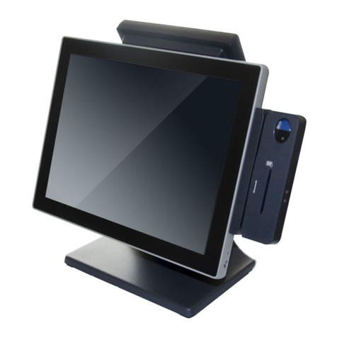
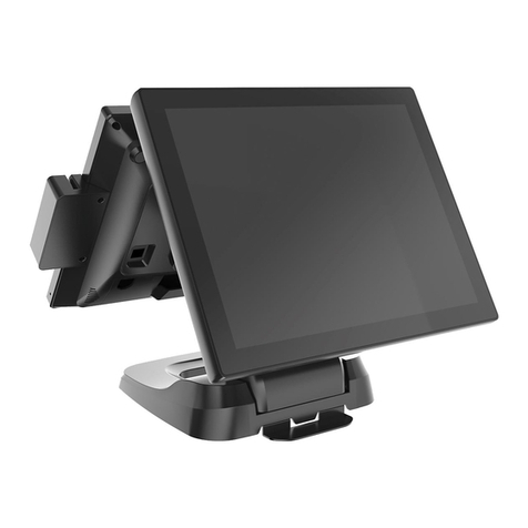
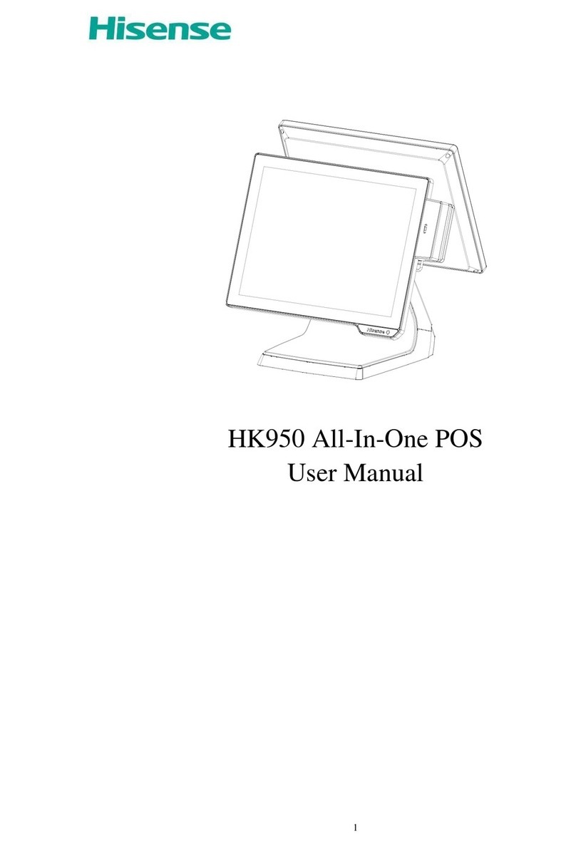
Hisense HK950 User manual

HK950 Service Manual
HISENSE INTELLIGENT COMMERCIAL SYSTEM CO. LTD.

HK950 Service Manual
Ⅰ. Product Introduction
1.1 basic introduction
The all-in-one POS HK950 is a new commercial POS with features of high performance, rich
configuration, low power consumption and easy maintenance. It provides more choices for customers.
HK950 fits for commercial department stores, restaurants, boutiques, cosmetics stores and other
industries, to provide a complete set of solutions.
1.2 basic configuration:
ainboard system platform:
1) Intel® Celeron® processor 3955U (Skylake) SOC 2.0Ghz dual-core dual-thread
power consumption 15W
2) Intel® Core® processor i3-6100U (Skylake) SOC 2.3Ghz dual-core four-thread power
consumption 15W
Memory DDR4L 4G maximum support 8GB
Hard disk:
1) HDD SATA 2.5 inch (500Gb Standard)
2) SATA 64 Gb SSD (larger capacity optional) or Larger
VFD guest, structure and HK900 / HK870 compatible
Multi-function card reader, support for MSR, RFID, USB interface fingerprint reader
5V / 12V power supply optional.)
HK950 Service Manual
1.3 The composition of whole machine
The whole machine is composed by LCD screen, touch screen, multi-card reader,
customer display, base composition.
IO panel
1.4 Use environment
Voltage: DC 24V bipolar with ground
Current: 2.5A.
Operating temperature: -10 ℃~ 50 ℃. (Suggestion: 15 ℃~ 30 ℃)
Working humidity: 10% ~ 90%. (Suggestion: 40% ~ 70%)
1.screen
2.base
3. MSR or RFID card reader
4.secondary screen
12V
DC
out
VGA
LAN
port
USB
Cash drawer
24V
pow
er in
AUDIO
1
2
3
4
COM
4
COM
3
COM
2
COM
1
HD
MI

HK950 Service Manual
Storage temperature: -30 ℃~ 70 ℃. (Suggestion: 15 ℃~ 30 ℃)
Storage humidity: 10% ~ 90%. (Suggestion: 40% ~ 70%)
1.5 Machine size and rotation angle
Ⅱ. Product main hardware configuration and specifications
2.1.Power
The whole machine adopts FSP060-DAAN2 24V DC power supply, input voltage range: AC 100V ~ 240V;
input frequency: 50Hz ~ 60Hz; output current: 2.5A; rated power: 60W;
1)Output specifications
Standard value
Prescribed value
Minimum value
Maximum value
+24.0V
22.8V-25.2V
0A
2.5A
2)Input voltage specifications
Minimum value
NOM.
Maximum value
90V
90/264
264V
3)Temperature specifications
Operating mode
0°C ~ +40°C
Storage mode
-20°C ~ +70°C
4)Humidity specifications
Operating mode
10%~90% RH,non-condensing
Storage mode
10%~90% RH,non-condensing
2.2 Mainboard
The Mainboard can use the following two types of system platforms:
1 \ Intel® Celeron® processor 3955U (Skylake) SOC 2.0Ghz dual-core dual-thread power consumption 15W.
2 \ Intel® Core® processor i3-6100U (Skylake) SOC 2.3Ghz dual-core four-thread power consumption 15W.

HK950 Service Manual
2.2.1 Mainboard appearance is as follows:
Mainboard
identifies
port
Port details
1.COM4
Serial port connector
Serial port 4 (live 5V / 12V)
2.COM3
Serial port connector
Serial port 3 (live 5V / 12V)
3.COM2
Serial port connector
Serial port 2 (live 5V / 12V)
4.COM1
Serial port connector
serial port 1
5.R_USB3
USB connector
rear double USB2.0 interface
6.R_USB1
USB connector
rear double USB3.0 interface
7.HDMI1
HDMI connector
rear HDMI interface
8.VGA1
VGA connector
Rear VGA port
9.CASH1
RJ11 connector
RJ11 interface ,24Vcash drawer
10.DC_IN1
DC 24V power connector
System power connector
11.DC_OUT1
DC 12V power output
12V power output
12.RJ45_1
LAN connector
Network Interface
13.JACK1
Headphone connector
Headphone jack
14.R_USB2
USB connector
Rear double USB2.0 interface
15.BAT1
CMOS Battery
Mainboard COMS battery
16.J_LPT1
LPT connector
Parallel printer interface
17.F_PANEL1
Front Panel connector
Switch board interface
18.J_SPK1
1*4Pin 2.0mm wafer box
Onboard speaker output
connector
19.TOUCH1
Resistive touch connector
Resistive touch screen interface
20.F_USB3
USB header
On-board USB interface
21. DIMM1
1*260pin SO-DIMM Socket
DDR4 memory interface
22. F_USB2
USB header
On-board USB interface
23.J_COM6
Serial port header
Onboard serial port 6
24.F_USB4
USB header
On-board USB interface
25. J_COM6
Serial port header
Onboard serial port 5

HK950 Service Manual
26.SIM1
MINIPCIE
SIM card
27.MINI_PCIE1
MINIPCIE
Wireless network card
28.MINI_PCIE2
Mini SATA
MSATA hard drive interface
29.LVDS_P1
LVDS Inverter power connector
LVDS power connector
30.CPU_FAN1
FAN connector
Smart fan interface
31.J_DEG1
Debug
debugging interface
32.P_SATA1
Serial Advanced Technology Attachment
Power Connector
SATA power connector
33.S_ATA1
Serial Advanced Technology Attachment
Connector
SATA data line interface
34.LVDS1
Low Voltage Differential Signaling
Transmitter Interface
LVDS interface
Mainboard rear IO ports panel
2.2.2 Mainboard basic parameters
PCB
PCB
Layer/size
6 layer/245*135mm
special
/
Chipset
CPU
Skylake-U 15W TDP 3955U/I3-6100U
CHIPSET
SOC
SUPER IO
ITE8785E/ITE8786E
RAM
RAM
PORT
AMOUNT
1*channel
PORT TYPE
SODIMM
SPECS
DDR4
NOTES
Ports definition
Graphics
VGA
Port Amount
1
Port Type
DB15+socket
DB15
1
Socket
Wafer 12*1 2.0mm
Fake Load
Null
Notes
HDMI
Port Amount
1
Port Type
Type A Vertical 90°
Notes
LVDS
Port Amount
1
Port Type
2*20 1.25mm white socket SMD

HK950 Service Manual
Bus type
PS8625 convert
Brightness control
PWM control
Notes
Network card:
Network card
Network card
Chip
Realtek 8111F
Port Amount
1
Port Type
RJ45
Wake on the internet
Support
ESD
Support
BYPASS
Null
NOTES
Audio card:
Audio card:
Audio card:
Chip
ALC662-VD
Amplifier type
TPA6017
Port Type
I2S PORT
Pins
1*LINE OUT+WAFER 4*1 2.00mm
Notes
Amplifier definition
1
R-
2
R+
3
L+
4
L-
COM Port
COM port
COM port
Port Amount
6
Port Type
COM 1-4 RS232 RJ50 10 PINS
COM 5-6 RS232 WAFER 5*2 PHD connectors
Live com ports
COM 2-4 jumper pin 10th RI\5V\12V selectable
Pins
Notes
COM1
1
NC
2
DCD
3
DSR
4
RXD
5
RTS
6
TXD
7
CTS
8
DTR
9
GND
10
RI
COM2-4
1
NC
2
DCD
3
DSR
4
RXD
5
RTS
6
TXD
7
CTS
8
DTR
9
GND
10
RI\5V\12V
COM5-6
DCD
RXD
TXD
DTR
GND
DSR
RTS
CTS
RI
NC

HK950 Service Manual
PS/2
Ps/2
Keyboard DB
1
Mouse DB
1
Pins
6*1 2.00 PH pins
Keyboard Startup
null
Notes
Power in
24V DC IN
24V DC IN
Port Amount
1
Port Type
S terminal 4pin
Voltage Range
24V
Notes
4pin DC jack definition
1.24V
2.24V
3.GND
4.GND
Cash drawer:
Cash drawer:
Cash drawer:
Port Amount
1
Port Type
STANDARD 24V RJ11 port
Notes
1.GND 2.CD1_OPEN 3.CD_SENSE
4.+24V 5.CD2_OPEN 6.GND
2.3 LCD display
Item
Specification
Product Type
15.0” TFT Liquid Crystal Display module with LED Backlight units and 20 pins
LVDS interface
Best display resolution
1024 x 768 XGA mode
Display color
16.2M/262k colors.
Frame size
307.4(H) x 231.3(V)
Visual area size
304.1 (H) x 228.1(V) (15.0” diagonal)
Operating mode
Temperature range
Humidity range
Remarks
-30°C ~ +80°C
90 %RH Max. (Ta ≦40℃)
Storage Mode
-40°C ~ +85°C
90 %RH Max. (Ta ≦40℃)
2.4 Capacitive touch screen
Item
Specification
Product Type
Projected Capacitive Touch Screen
Touch mode
Finger touch, pen touch
connection
FPC connection cable (length 90mm)
1
2
3
4

HK950 Service Manual
Connection mode
USB
Frame size
354.1 mm X 277.1 mm X 2.4T
Visual area size
305.1 mm X 229.1 mm
total thickness
3.20 ±0.20 mm
Operating mode
Temperature range
Humidity range
Remarks
-10°C ~ +60°C
90% RH at max 50°C
Storage Mode
-20°C ~ +70°C
90% RH at max 50°C
Transmittance
85% ± 2%
Operating life
click life of not less than 1 million times
Strokes life of not less than 100,000 times
Support OS
Android、Linux、XP、Win7、Win8、Win10
Touch point
support 10 points touch
2.5 OS supported
OS
version
touch
notes
windows
win10
32BIT
supported
64BIT
supported
WIN7
32BIT
supported
64BIT
supported
LINUX
Redhat Server
64BIT
supported
CentOS 6.4
64BIT
supported
Ubuntu 14.04
64BIT
supported
ubuntu-14.10-desktop-i386
supported
Ⅲ. Product disassembly and replacement of major parts
3.1 disassemble tool
The main tools:
1) Phillips screwdriver
Specifications: Length 150-200mm (not included)
Uses: When used to disassemble parts, unscrew or install the fixing screws.
2) screw box:
Uses: used to place the screws removed.
3) Flathead screwdriver
Uses: used to remove the drawing chassis.

HK950 Service Manual
3.2 machine disassemble and replacement steps
3.2.1.MSR removal and replacement
Step 1: Remove the card reader USB cable and the fixed card under pressure;
Step 2: According to the direction of construction plans to promote the magnetic card reader to remove it for
replacement;
3.2.2. Hard disk removal and replacement
Step 1: Press both sides of the hard disk with plastic fixing bracket and pull the bracket in the direction of the arrow
to remove the hard disk.
Step2: Remove the hard disk from its mounting bracket and replace it;
3.2.3. second screen LCD disassembly and replacement
Step 1: Dial the lock to " " as shown, remove the front bezel as the picture shows;
Step 2: Remove the second screen from the base by removing the three screws on the second screen mounting
bracket (base end) and the two fixing screws on the pressboard.
Step 3: Remove the second screen of the four screws (monitor side) after the second screen to be replaced;

HK950 Service Manual
3.2.4. Mainboard and memory removal and replacement
Step 1: repeat the action of 3.2.3, remove the base front cover and unplug the connection cable on the Mainboard
side;
Step 2: Remove the two fixing screws of the mainframe to remove it from the base as shown in the figure;
Step 3: Remove the two fixing screws of the rear case of the main body and remove it.
Step 4: Remove the hard disk bracket, heat sink, Mainboard screws, remove all kinds of cables on the Mainboard,
Mainboard and memory replacement;

HK950 Service Manual
3.2.5. LCD screen (main screen) removal and replacement
Step 1: Repeat the actions of 3.2.3 and 3.2.4, remove the main frame and remove the cable between the LCD panel
and the Mainboard;
Step 2: The LCD panel metal shield 10 fixed removed and removed;
Step 3: Remove the cable and touch panel (glue) from the LCD panel;
Step 4: Remove theLCD fixing screws (two on each side) on the fixing bracket to replace the LCD panel;
SSD bracket
Heat sink
RAM

HK950 Service Manual
3.2.6. Touch screen removal and replacement
Step 1: Repeat the actions of 3.2.4 and 3.2.5 to remove the components of the touch screen and the front shell kit;
Step 2: Take a new touch screen and front shell kit, installed on the host;
Notes: touch panel is pasted to front shell by 3M tape tightly, so it is hard to disassemble the touch screen and
front shell, so we suggest you may replace front shell and touch panel assy to avoid part damage. The parts
needed as below:
PART
CODE
DESCRIPTION
QUAN
NOTES
P013100
Touch panel\DY1502S-2209
1
PCT touch
P0360126
Front shell\HK950 主机\HZS8.074.207\ABS\银\喷漆\无丝印
1
P065024
Double side tape
1
Ⅳ. Ⅳ.Common Fault Analysis And Solution
4.1 Possible Cause of Common Faults
1)normal malfunctions: mainly caused by normal wear and end of service life, or natural aging;
触摸屏控制板(胶粘)

HK950 Service Manual
2)human-caused malfunctions: components are damaged due to not complying with the operating rules such as
insert and pull the plug in a working condition etc.
3)hardware malfunctions: problems of manufacturing process or material quality problem;poor contact
between boards and connectors;board solder joint is broken or unstable、the connecting wires break down etc.
4)software malfunctions:it can be divided into the fault caused by the human reason、the fault caused by
system software and the application itself, and the fault caused by virus;
5)impact caused by the environment:it mainly includes voltage anomaly fluctuation, temperature and humidity,
dust, electromagnetic radiation, electrostatic and other factors ;
4.2 Principle of handling faults
1)From software to hardware:The fault should be analyzed first from the operating system and software,for
example: The partition table is missing、COMS is improperly set up、the virus destroy the system.The error of hard
disk main boot sector or the register file. After eliminating the errors of software, we can start diagnosis the cause of
the failure from the hardware aspect.
2)From the outside to the inside:We should diagnosis the peripheral first ,then turn to the host, fault diagnosis
should be based on the system error;
3)Power supply first:Power supply is the key to whether the machine can work normally, so we should check
the power supply first and then diagnosis the other parts.
4)From general to special:Consider the most likely cause of failure, for example: If the hard disk cannot work
normally, we should check if the power cable and the data line is loose, reconnecting them can solve the problem.5)
From simple to complex:First eliminate some faults that are easy to work out, then eliminate those faults that are not
easy to solve.
4.3 Common methods of eliminating the faults
1)observation
Choose what to observe based on the specific situation,use your eyes、ears、nose and other organs to judge the
failure, observe if there is charred、variant、abnormal sound、falling off and other phenomena;
The principles of observation are as follows:
From outside to inside:observe the environment of the outside and inside of the machine;
From simple to complex:look、listen and smell;then have a measurement or test.
2)re-install method
Remove the board which may have a fault,wipe it clean with rubber and then re-insert to make sure it is in a
good contact.
3)replacement method
Replace the defective part with a similar one which have the same functions to find out if the failure is gone.
4)minimum system method

HK950 Service Manual
Remove all the peripheral components and host hardware remaining power supply、Mainboard、cpu these three
components,plug in and observe if it works normally, if there is no faults we can install other parts step by step until
the whole machine cannot work normally, find out the error part and repair it.
5)heating and cooling method
Use finger to touch the heating part and observe if there is overheating; cool the abnormally heating part with an
absorbent cotton swab containing absolute ethanol, if the failure eliminates, it can proves that the failure is caused by
the overheating stability.
4.4 Common Troubleshooting
1)common error message tips and solutions when the boot
Error prompt
Cause
Solution
BIOS ROM checksum error:
System halted
BIOS ROM program data has
been changed or BIOS chip is
damaged
1) Restart the computer into the BIOS and load
the default settings
2) Remove the CMOS battery for about 10
seconds, discharge the CMOS, and then enter
the BIOS to load the default settings
CMOS battery failed or
CMOS battery state low
CMOS battery power shortage
Replace a new CMOS battery
CMOS checksum
error-Defaults loaded
CMOS battery power shortage,
or may be caused by CIH virus
problems
1) enter into the BIOS to load the default
settings, 2) for the CMOS battery discharge, and
then load the BIOS default settings, 3) try
another CMOS battery
CMOS System Options Not
Set
The data stored in the CMOS is
corrupted or does not exist
Load BIOS default settings
Press F1 to continue Del to
setup
BIOS settings problems, it may
be a hardware installation
problems, such as hard disk
installation is not correct
1) load the BIOS default settings; 2) or check
the hardware whether has problem
Memory Test Fail
Memory installation is not
strong or damaged, it may not
memory compatibility, or BIOS
and memory-related settings are
not appropriate, such as memory
frequency and actual value does
not match
1) first load the BIOS default settings try, 2)
re-insert the memory or replace the new
memory to try
Keyboard Error
Keyboard damage or poor
connection status
Check whether the keyboard is plugged well or
the keyboard interface is good
Hard disk Install Failure
HDD port bad connection or
HDD damaged
Check whether the hard disk interface is
connected properly, replace the new hard drive
to test
HDD controller Failure
HDD port not good
Check whether the hard disk interface is
connected properly
Hard disk(s) diagnosis fail
HDD damaged
Connect the hard disk to another device to
check for proper operation
Primary master hard disk fail
HDD fault
1) Load the BIOS default settings to try
2) Check the hard disk interface status is good
C drive error
The BIOS does not receive a
signal from the hard disk C
1) Check the hard disk interface is correct
2) load the BIOS default settings to try
Override enable-defaults
BIOS settings are not suitable
1) Load the BIOS default settings to try

HK950 Service Manual
loaded
for the device (for example, the
memory can only run 1000
MHz, but the actual set to
1333MHz)
2) CMOS discharge to load the BIOS default
settings
Disk BOOT failure ,Insert
system disk and press enter
Hard disk is not well installed or
hard disk master boot record
error
1) reinstall the hard disk, 2) load the BIOS
default settings to try, 3)load into the DOS with
boot disk, execute the F disk / MBR command
Invalid partition table
1)load into the DOS with boot disk, implement
of F disk / MBR command 2) re-partition for
the hard disk
Miss operation system
Can not find hard disk DOS
boot record
Format C drive: Format C / s
Long stay in the "Verifying
DMI pool Data" interface
Hard disk master boot record is
corrupted or operating system
problems
1) check the BIOS set up with what equipment
to start the system, and changed to hard disk
boot; 2) see if the BIOS can detect the hard
disk, if not detect, then bad hard disk or hard
disk damage; 3) if the hard disk installation or
Their own have no problem, if no important
data, hard disk can be re-zoning; 4) re-partition
for the hard disk, re-install the operating system
2)common error message tips and solutions of LCD
Common fault
Cause reason and solution
Black screen
Possible cause:mainboard fault, LVDS cable or LED cable faulty、LCD faulty;
solution: Use the substitution method to troubleshoot the relevant parts in the
following order
LVDS or LED cable LCD mainboard
Flower screen ,white
screen , unormal color
Possible cause:mainboard fault, LVDS cable or LED cable faulty、LCD faulty
solution: Use the substitution method to troubleshoot the relevant parts in the
following order
LVDS cable LCD mainboard
Screen dark(no display、
flickering screen)
Possible cause:mainboard fault, LVDS cable or LED cable faulty、LCD faulty
solution: Use the substitution method to troubleshoot the relevant parts in the
following order
LCD cable LCD mainboard
Bright line
Possible cause:LCD cable faulty or LCD faulty
solution: replace new LCD or replace new LCD cable
3)common error message tips and solutions of Touch panel
Common fault
Cause reason and solution
Touch panel not working
good
Possible cause:touch controller fault, driver lost; touch screen faulty ,mainboard
faulty, cable faulty or cable bad connection status
solution: Use the substitution method to troubleshoot the relevant parts in the
following order
drivers USB cable touch controller touch screen mainboard
Touch panel no function
Possible cause:touch controller fault, driver lost; touch screen faulty ,mainboard
faulty, cable faulty or cable bad connection status
solution: Use the substitution method to troubleshoot the relevant parts in the
following order
drivers USB cable touch controller touch screen mainboard

HK950 Service Manual
4)common error message tips and solutions of Mainboard
Common fault
Cause reason and solution
Startup automatically when
connected to power
Possible cause:maybe mainboard is faulty
Solution: replace the mainboard
not power on
Possible cause: faulty adapter ; mainboard faulty; RAM damaged ; BIOS faulty
Solution:
1) replace new mainboard
2) replace new adapter
3) remove the cmos battery and short-circuit related IC and install cmos
battery back
4) replace new RAM.
Port not working
Possible cause: port faulty, port cable status bad, mainboard faulty
Solution: replace new mainboard or replace related I/O board or related cables
Not access to LAN
Possible cause: drivers lost; port damaged
1) replace the mainboard
2) install drivers
3) replace new LAN cable
5)common error message tips and solutions of HDD or SSD
Common fault
Cause reason and solution
Can’t access to OS; It
prompt:“Device error”
when startup,or:“Non-
System disk or disk error,
Replace and strike any key
when ready”
Possible cause :CMOS fault ,mainboard fault ,OS fault , hard drive fault
Solution
1)remove the CMOS battery and short-circuit related IC, then install back CMOS
battery
2)reinstall OS
3)replace HDD or SSD
4)replace new mainboard
It prompts:“Invalid
partition table”
Possible cause: SSD record data fault
solution:
1) reload OS
2) replace new SSD and reload OS
It prompts “Error loading
operating
system”or“Missing
operating system”
Possible cause :CMOS fault ,mainboard fault ,OS fault , hard drive record data
fault
Solution:
1)remove the CMOS battery and short-circuit related IC, then install back CMOS
battery
2)reinstall OS
3)replace HDD or SSD
4)replace new mainboard
It prompts “TRACK 0
BAD,DISK UNUSABLE”
Possible cause: SSD fault;
solution:
1)replace new SSD;
SSD read/write speed
slow,OS crash or reboot
Possible cause: OS fault; SSD fault,
solution:
1) replace new SSD;
2) reload OS;
3) use software to recover SSD

HK950 Service Manual
6)common error message tips and solutions of RAM
Common fault
Cause reason and solution
Cannot access to OS and
alarm
Possible cause:RAM slot faulty,RAM faulty ,OS faulty ,mainboard faulty
Solution:
1)reload OS
2)replace new RAM,3)replace new mainboard.
Blue screen or crash
Possible cause:OS fault, software fault,RAM fault ,mainboard fault
Solution:
1)reload OS,
2)replace new RAM ,
3)replace new mainboard
System reboot
automatically many times
when system boot.
Possible cause:OS fault ;RAM faulty or mainboard faulty
Solution:
1)reload OS,
2)replace new RAM or replace new mainboard
Other manuals for HK950
1
Table of contents
Other Hisense Touch Terminal manuals

Hisense
Hisense HK950 User manual

Hisense
Hisense HK800 SERIES User manual

Hisense
Hisense HK716 Series Quick setup guide

Hisense
Hisense HK570 User manual

Hisense
Hisense HK800 SERIES User manual

Hisense
Hisense HM626R User manual

Hisense
Hisense HK900A User manual

Hisense
Hisense HK560 User manual

Hisense
Hisense HK870 Series Quick setup guide

Hisense
Hisense HK560 User manual