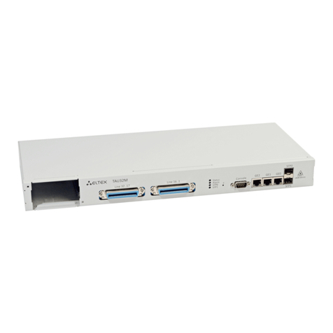
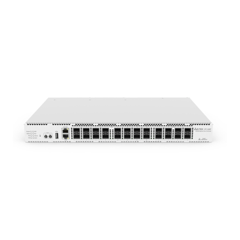
ELTEX LTP-16N User manual

Optical line terminals
LTP-16N, LTP-16NT
User Manual, Issue 2 (28.05.2021)
Firmware version1.2.0

OLT LTP-16N, LTP-16NT. User Manual
2
Contents
1 Terms and Definitions .............................................................................................................6
2 General information.................................................................................................................7
2.1 Introduction ..............................................................................................................................7
2.2 Purpose ....................................................................................................................................7
2.3 Delivery Package......................................................................................................................7
2.4 Technical specifications..........................................................................................................8
2.5 Compatible SFP transceivers............................................................................................... 11
2.6 Design.................................................................................................................................... 12
2.6.1 Front panel ......................................................................................................................12
2.6.2 Rear panel........................................................................................................................14
2.6.3 LED Indication .................................................................................................................15
2.6.4 Temperature sensors .....................................................................................................16
2.6.5 Ventilation system ..........................................................................................................17
2.7 Safety rules and Installation procedure............................................................................... 17
2.7.1 Introduction .....................................................................................................................17
2.7.2 Safety requirements .......................................................................................................17
2.7.3 Terminal installation .......................................................................................................18
3 Getting Started with the terminal......................................................................................... 22
3.1 Connecting to the Terminal CLI ........................................................................................... 22
3.1.1 Introduction .....................................................................................................................22
3.1.2 Connecting to CLI via COM port.....................................................................................22
3.1.3 Connecting to CLI via Telnet protocol ...........................................................................23
3.1.4 Connecting to CLI via Secure Shell protocol.................................................................25
3.2 Getting Started with terminal CLI......................................................................................... 25
3.2.1 Introduction .....................................................................................................................25
3.2.2 CLI views hierarchy.........................................................................................................25
3.2.3 CLI hotkeys......................................................................................................................27
3.2.4 CLI automatic code completion.....................................................................................27
3.2.5 Group operations ............................................................................................................28
4 Configuring the terminal....................................................................................................... 29
4.1 Terminal configuration ......................................................................................................... 29
4.1.1 Introduction .....................................................................................................................29
4.1.2 Configuration lifecycle....................................................................................................29
4.1.3 Creating a configuration backup....................................................................................29
4.1.4 Configuration restore......................................................................................................30
4.1.5 Configuration reset .........................................................................................................30

OLT LTP-16N, LTP-16NT. User Manual
3
4.2 Network settings................................................................................................................... 30
4.2.1 Introduction .....................................................................................................................30
4.2.2 Network parameters configuration................................................................................30
4.3 User management ................................................................................................................ 32
4.3.1 Introduction .....................................................................................................................32
4.3.2 User list preview..............................................................................................................35
4.3.3 Adding a new user ..........................................................................................................36
4.3.4 Changing user password................................................................................................36
4.3.5 Viewing and changing user access rights.....................................................................36
4.3.6 Deleting a user ................................................................................................................37
4.4 Services configuration.......................................................................................................... 37
4.4.1 Introduction .....................................................................................................................37
4.4.2 SNMPD configuration.....................................................................................................37
4.4.3 LOGD configuration ........................................................................................................38
4.4.4 ALARMD configuration...................................................................................................42
4.5 VLAN Configuration.............................................................................................................. 44
4.5.1 Introduction .....................................................................................................................44
4.5.2 VLAN Configuration........................................................................................................45
4.5.3 VLAN Configuration........................................................................................................45
4.5.4 VLAN Deletion .................................................................................................................46
4.6 IGMP configuration.............................................................................................................. 46
4.6.1 Introduction .....................................................................................................................46
4.6.2 Enabling snooping ..........................................................................................................46
4.6.3 Report proxying...............................................................................................................46
4.7 DHCP Configuration.............................................................................................................. 47
4.7.1 Introduction .....................................................................................................................47
4.7.2 DHCP snooping...............................................................................................................47
4.7.3 DHCP option 82...............................................................................................................47
4.8 PPPoE configuration............................................................................................................. 50
4.8.1 Introduction .....................................................................................................................50
4.8.2 PPPoEsnooping .............................................................................................................50
4.8.3 PPPoEintermediate agent .............................................................................................50
4.9 Interface configuration ......................................................................................................... 52
4.9.1 Introduction .....................................................................................................................52
4.9.2 10G-front-ports configuration ........................................................................................53
4.9.3 GPON interface configuration........................................................................................54
4.10 LAG configuration................................................................................................................. 54
OLT LTP-16N, LTP-16NT. User Manual
4
4.10.1 Introduction .....................................................................................................................54
4.10.2 LAG configuration...........................................................................................................54
5 ONT configuration ................................................................................................................ 56
5.1 Service Models...................................................................................................................... 56
5.1.1 Introduction .....................................................................................................................56
5.1.2 VLAN ID replacement; The concept of pon vid .............................................................56
5.1.3 Operating principle..........................................................................................................56
5.1.4 ONT licensing..................................................................................................................58
5.1.5 Introduction .....................................................................................................................58
5.1.6 Loading a license file to OLT..........................................................................................59
5.1.7 Deleting a license file from OLT.....................................................................................59
5.2 ONT configuration ................................................................................................................ 60
5.2.1 Introduction .....................................................................................................................60
5.2.2 ONT operation modes ....................................................................................................60
5.2.3 General principles of configuration ...............................................................................60
5.2.4 ONT profiles configuration.............................................................................................61
6 Terminal monitoring ............................................................................................................. 68
6.1 General information.............................................................................................................. 68
6.1.1 Information on current terminal firmware version........................................................68
6.1.2 Terminal information preview ........................................................................................68
6.1.3 Network connection check.............................................................................................69
6.2 Terminal operation log ......................................................................................................... 70
6.3 Active alarms log .................................................................................................................. 70
6.4 10G-front-port monitoring .................................................................................................... 70
6.4.1 View port statistics .........................................................................................................70
6.4.2 View port state ................................................................................................................71
6.5 gpon-port monitoring............................................................................................................ 71
6.5.1 View port state ................................................................................................................71
6.6 MAC table monitoring........................................................................................................... 71
6.7 ONT monitoring..................................................................................................................... 72
6.7.1 ONT configurations list...................................................................................................72
6.7.2 List of empty ONT configurations..................................................................................72
6.7.3 View the list of unactivated ONTs .................................................................................73
6.7.4 List of connected ONTs..................................................................................................73
6.7.5 List of disconnected ONTs.............................................................................................75
6.7.6 ONT statistics .................................................................................................................75
6.8 System environment configuration ..................................................................................... 76

OLT LTP-16N, LTP-16NT. User Manual
5
7 Terminal maintenance.......................................................................................................... 77
7.1 SFP transceivers replacement ............................................................................................. 77
7.2 Ventilation units replacement .............................................................................................. 78
7.3 Power module replacement ................................................................................................. 78
7.4 OLT firmware update............................................................................................................ 79
8 The list of changes ............................................................................................................... 80

OLT LTP-16N, LTP-16NT. User Manual
6
1 Terms and Definitions
CBR Constant bitrate
DBA Dynamic bandwidth allocation
DHCP Dynamic Host Configuration Protocol
ERPS Ethernet Ring Protection Switching
FTP File Transfer Protocol
FW Firmware
GPON Gigabit PON
HSI High Speed Internet
IGMP Internet Group Management Protocol
IP Internet protocol
MLD Multicast Listener Discovery
OLT Optical Line Terminal
ONT Optical Network Terminal
ONU Optical Network Unit
PCB Printed Circuit Board
PPPOE Point-to-point protocol over Ethernet
SLA Service Level Agreement
SNTP Simple Network time protocol
SNMP Simple Network Management Protocol
SFP Small Form-factor Pluggable
TFTP Trivial File Transfer Protocol
URI Uniform Resource Identifier
VEIPVirtual Ethernet Interface Point
Notes and warnings
Notes contain important information, tips or recommendations on device operation and configuration.
Warnings are used to inform the user about harmful situations for the device and the user alike, which
could cause malfunction or data loss.

OLT LTP-16N, LTP-16NT. User Manual
7
•
•
•
•
•
•
•
•
•
•
•
•
•
•
•
•
1.
2.
3.
4.
2 General information
2.1 Introduction
A GPON is a network of passive optical networks (PON) type. It is one of the most effective state-of-the-art
solutions for the 'last mile' issue that significantly reduces the required amount of cable and provides data
transfer with downstream rate up to 2.5Gbps and upstream rate up to 1.25Gbps. Being used in access
networks, GPON-based solutions allow end users to have access to new services based on IP protocol in
addition to more common ones.
The key GPON advantage is the use of one optical line terminal (OLT) for multiple optical network terminals
(ONT). OLT converts Gigabit Ethernet and GPON interfaces and is used to connect a PON network with data
communication networks of a higher level.
The range of OLT GPON equipment produced by Eltex comprises of LTP-16N and LTP-16NT terminals with
internal Ethernet switch with RSSI function and 16GPON ports.
This user manual describes purpose, main technical specifications, installation order, rules of configuration,
monitoring, and software update for the devices.
2.2 Purpose
The LTP-16N(T) optical line terminal is designed to establish connection with upstream equipment and provide
broadband access across passive optical networks. Ethernet connection is established through Gigabit uplink
and 10G Base-X interfaces; GPON interfaces are used to connect to optical networks.Each PON interface
allows connection of up to 128subscriber optical terminals through one fibre and supports dynamic
bandwidth allocation (DBA).
The following services are provided to end users:
voice communications;
HDTV;
VoIP;
high-speed access to the Internet;
IPTV;
video-on-demand (VoD);
video conferencing;
online educational and entertainment programs.
The device supports the following functions:
dynamic bandwidth allocation (DBA);
security functions;
remote ONT management;
power measurement support for signals received from each ONT (RSSI);
VLAN organisation (VLAN ID range: 1–4094);
support for IGMP snooping v1/2/3, IGMP proxy;
support for PPPoEintermediate agent;
support for DHCP Snooping, DHCP option 82.
2.3 Delivery Package
The standard delivery package includes:
LTP-16N/16NT optical line terminal;
Mounting set for 19'' rack.
RJ-45 – DB9(F) console cable;
CD with Operation Manual and Quick Configuration Guide (optional);

OLT LTP-16N, LTP-16NT. User Manual
8
5.
6.
7.
8.
Power cable (if equipped with 220V power supply);
Informational leaflet;
Declaration of conformity;
Technical passport.
2.4 Technical specifications
Table 1 – Main specifications of the line terminal
Interfaces
Number of Ethernet interfaces LTP-16N/LTP-16NT 9
Connector RJ-45 - 1 SFP - 8
Data rate, Mbps 10/100/1000
duplex/half-duplex
1000/10000
duplex
Standards 1GBase-X 10GBase-X
Standards IEEE 802.1D, IEEE 802.1p, IEEE 802.1Q
Number of PON interfaces LTP-16N/LTP-16NT 16
Connector type SC/UPC (socket)
in accordance with ITU-T G.984.2, FSAN Class B+, FSAN Class C++,
SFF-8472
Transmission medium SMF – 9/125, G.652 fibre optical cable
Standards Digital RSSI (Received Signal Strenght Indication)
Splitting ratio 1:4, 1:8, 1:16, 1:32, 1:64, 1:128
Class B+ Class C++
Range of coverage 20 km 40 km
Transmitter 1490 nm DFB Laser 1490 nm DFB Laser
Data rate 2488 Mbps 2488 Mbps

OLT LTP-16N, LTP-16NT. User Manual
9
Average output power +1,5..+5 dBm +7..+10 dBm
Spectral line width with -20dB 1.0 nm 1.0 nm
Receiver: 1310 nm APD/TIA 1310 nm APD/TIA
Data rate 1244 Mbps 1244 Mbps
Receiver sensitivity -28 dBm -32 dBm
Receiver optical congestion -8 dBm -12 dBm
Synchronization ports Only for LTP-16NT
Processor
Processor type Intel Atom, x86_64
Clock frequency 2.1 GHz
Core quantity 4
RAM LTP-16N/LTP-16NT 8 GB
Non-volatile memory LTP-16N/LTP-16NT 8 GB
Switch
Ethernet switch Broadcom Packet Processor
Switch performance 120 Gbps
MAC table 64K entries
VLAN support up to 4K in accordance with 802.1Q

OLT LTP-16N, LTP-16NT. User Manual
10
Control
Local control CLI – command line interface
Remote management CLI (SSH, Telnet), SNMP
Monitoring CLI, SNMP
Access restriction by password, by privelege level
General parameters
Power supply AC: 150..250V, 50 Hz
DC: -36..-72V
Maximum power consumption LTP-16N/LTP-16NT 75 W
Operating temperature range from -5 to +40°C
Relative humidity Up to 80%
Dimensions (WxHxD) 19", 1U
Dimensions with an installed power module:
430x42x305 mm
Weight Complete set
LTP-16N/LTP-16NT 3.5 kg
Modules
Power module 0.5 kg

OLT LTP-16N, LTP-16NT. User Manual
11
2.5 Compatible SFP transceivers
Correct and error-free operation of GPON interface requires exact parameters to be chosen and set for each
transceiver type. This can be done only under laboratory conditions by the terminal vendor. Table 2 lists SFP
transceivers for which seamless terminal operation is guaranteed.
DDMI (Digital Diagnostic Monitoring Interface) provides information on transceiver parameters, such as
temperature, power voltage, etc. DDMI also measures the level of ONT signal (RSSI). All compatible
transceivers support this function.
Table 2 – List of compatible SFP transceivers
Vendor SFP transceiver module Class DDMI
NEOPHOTONICS PTB38J0-6538E-SC B+ +
NEOPHOTONICS 38J0-6537E-STH1+ C+ HP +
NEOPHOTONICS 38J0-6537E-STH2+ C+ HP +
NEOPHOTONICS 38J0-6537E-STH3+ C+ HP +
Ligent Photonics LTE3680M-BC B+ +
Ligent Photonics LTE3680M-BH B+ +
Ligent Photonics LTE3680P-BC C+ +
Ligent Photonics LTE3680P-BC+1 C+ +
Ligent Photonics LTE3680P-BH C+ +
Ligent Photonics LTE3680P-BC2 C+ HP +
Hisense LTE3680M-BC+ B+ +
Hisense LTE3680M-BC+2 C+ +

OLT LTP-16N, LTP-16NT. User Manual
12
•
•
2.6 Design
2.6.1 Front panel
The devices have a metal housing available for 19” form-factor rack mount; housing size is 1U. The front panel
layout is shown in figures 1 and 2. Tables 3 and 4 list connectors, LEDs and controls located on the front panel
of the terminal.
Figure 1 – LTP-16N front panel layout
Table 3 – Description of the connectors, LEDs, and controls located on the front panel of LTP-16N
# Front panel element Description
1PS2 Redundant power supply indicator
2PS1 Primary power supply indicator
3Status Device operation indicator
4Power Device power indicator
5SSD SSD operation indicator
6FAN Ventilation panels operation indicator
7FFunctional key that reboots the device and resets it to factory
default configuration:
pressing the key for less than 15 seconds reboots the
device;
pressing the key for more than 15 seconds resets the
device to factory default configuration.
8USB USB port
9Console DB9F — RJ45 console port
10 Alarm Alarm indicator
11 OOB Port for connection the board via network

OLT LTP-16N, LTP-16NT. User Manual
13
•
•
# Front panel element Description
12 PON 1..16 GPON interfaces. 16 chassis for installing xPON 2.5G SFP
modules
13 10/1GE Uplink interfaces. 8 chassis for installing 10G-BASE-X SFP
modules
Figure 2 – LTP-16NT front panel layout
Table 4 – Description of the connectors, LEDs, and controls located on the front panel of LTP-16NT
# Front panel element Description
1PS2 Redundant power supply indicator
2PS1 Primary power supply indicator
3Status Device operation indicator
4Power Device power indicator
5SSD SSD operation indicator
6FAN Ventilation panels operation indicator
7FFunctional key that reboots the device and resets it to factory
default configuration:
pressing the key for less than 15 seconds reboots the
device;
pressing the key for more than 15 seconds resets the
device to factory default configuration.
8Console DB9F — RJ45 console port
9Sync Synchronization operation indicator

OLT LTP-16N, LTP-16NT. User Manual
14
# Front panel element Description
10 Alarm Alarm indicator
11 Sync ports Synchronization interfaces
12 USB USB port
13 OOB Port for connection the board via network
14 PON 1..16 GPON interfaces. 16 chassis for installing xPON 2.5G SFP
modules
15 10/1GE Uplink interfaces. 8 chassis for installing 10G-BASE-X SFP
modules
2.6.2 Rear panel
The rear panel of the device is shown in Figure3.
Table below lists rear panel connectors.
Figure 3 – LTP-16N/16NT optical line terminal rear panel
Table 5 – Rear panel connectors description
Rear panel element Description
160..250 VAC, 50Hz, max 1A;36..72 VDC, max 5A Connectors for AC/DC power supply
Earth bonding point Earth bonding point
Fan1, Fan2 Ventilation units

OLT LTP-16N, LTP-16NT. User Manual
15
2.6.3 LED Indication
The indicators located on the front panel show the status of the terminal. Table 6 provides possible statuses
of the LEDs.
Table 6 – LTP-16N/16NT status light indication
LED name Indicator State Device state
Power Solid green Power is on, normal device operation
Off Power is off
Red Primary power supply failure
Status Solid green Normal operation
Solid red Operation failures
Fan Solid green All fans are operational
Flashing red One or more fans are failed
PS1 Solid green Primary power supply is connected and operates
correctly
Disabled Primary power supply is not connected
Red Primary power supply is missing or failed.
PS2 Solid green Redundant power supply is connected and operates
correctly
Disabled Redundant power supply is not connected
Red The primary source of the redundant power supply is
unavailable or the redundant power supply failed
Alarm Green Correct device operation
Flashing red Alarm
SSD Disabled Cannot reach the drive
Flashing green The drive is being accessed

OLT LTP-16N, LTP-16NT. User Manual
16
LED name Indicator State Device state
Sync Solid green Synchronization is in process
Disabled Synchronization is disabled
2.6.4 Temperature sensors
4 temperature sensors are used to measure temperature inside the terminal case: 3 external and 1 into switch.
Figure 4 shows the sensor location on PCB.
Figure 4 – Temperature sensors allocation
Table 7 – Temperature sensors description
Rear panel element Description
Temperature sensor 1 PON-ports SFP 1
Temperature sensor 2 PON-ports SFP 2
Temperature sensor 3 Front-ports SFP

OLT LTP-16N, LTP-16NT. User Manual
17
1.
2.
3.
•
•
•
4.
5.
Rear panel element Description
Temperature sensor 4 Switch
2.6.5 Ventilation system
There are ventilation openings on the device rear, front and side panels that serve to remove heat. There are
two ventilation units on the rear panel (Figure 3).
Air flows in through the perforated front and side panels, circulates through all internal components, cools
them down, and then is removed by fans located on the perforated rear panel.
The device contains two blocks of two fans each. The ventilation units are detachable. The procedure for
dismantlement and installation is described inVentilation Units Replacement.
2.7 Safety rules and Installation procedure
2.7.1 Introduction
This section describes safety measures and installation of the terminal into a rack and connection to a power
supply.
2.7.2 Safety requirements
General requirements
Any operations with the equipment should comply to the Safety Rules for Operation of Customers' Electrical
Installations.
Before operating the device, all engineers should undergo special training.
Connect only serviceable and compatible accessories to the terminal.
To avoid overheating and provide necessary ventilation of the terminal, sufficient space should be
provided above and below the terminal.
The device could be permanently used provided the following requirements are met:
ambient temperature from -5 to +40°C;
relative humidity up to 80% at +25°C;
atmosphere pressure from 6,0x10*4 to 10,7x10*4 Pa (from 450 to 800 mmHg).
The terminal should be not be exposed to mechanical shock, vibration, smoke, dust, water, and
chemicals.
To avoid components overheating which may result in device malfunction, do not block air vents or
place objects on the equipment.
Operations with the terminal should be carried out only by personnel authorised in accordance with the
safety requirements.

OLT LTP-16N, LTP-16NT. User Manual
18
1.
2.
3.
4.
•
•
•
•
•
•
Electrical Safety Requirements
Prior to connecting the device to a power source, ensure that the equipment case is grounded with an
earth bonding point. The earthing wire should be securely connected to the earth bonding point. The
resistance between the earth bonding point and earthing busbar should be less than 0,1 Ω. PC and
measurement instruments should be grounded prior to connection to the terminal. The potential
difference between the equipment case and the cases of the instruments should be less than 1V.
Prior to turning the device on, ensure that all cables are undamaged and securely connected.
Make sure the device is off, when installing or removing the case.
Follow the instructions given in SFP transceivers replacement to install or remove SFP transceivers. This
operation does not require the terminal to be turned off.
2.7.3 Terminal installation
Check the device for visible mechanical damage before installing and turning it on. In case of any damage,
stop the installation, fill in a corresponding document and contact your supplier. If the terminal was exposed to
low temperatures for a long time before installation, leave it for 2 hours at ambient temperature prior to
operation. If the device was exposed to high humidity for a long time, leave it for at least 12 hours in normal
conditions prior to turning it on.
Support brackets mounting
The delivery package includes support brackets for rack installation and mounting screws to fix the terminal
case on the brackets. To install the support brackets:
Step 1. Align six mounting holes in the support bracket with the corresponding holes in the side panel of
the device.
Step 2. Use a screwdriver to screw the support bracket to the case.
Step 3. Repeat steps 1 and 2 for the second support bracket.
Figure 5 – Support brackets mounting
Terminal rack installation
To install the terminal to the rack:
Step 1. Attach the terminal to the vertical guides of the rack.
Step 2. Align mounting holes in the support bracket with the corresponding holes in the rack guides. Use
the holes of the same level on both sides of the guides to ensure the device horizontal installation.
Step 3. Use a screwdriver to screw the terminal to the rack.

OLT LTP-16N, LTP-16NT. User Manual
19
Figure 6 – Device rack installation
The terminal is horizontally ventilated. The side panels have air vents. Do not block the air vents to avoid
components overheating and subsequent terminal malfunction.
To avoid overheating and provide necessary ventilation of the terminal, sufficient space should be
provided above and below the terminal, not less than 10cm.

OLT LTP-16N, LTP-16NT. User Manual
20
Power module installation
Depending on power supply requirements, terminals can be supplemented with either an AC power module,
220V, 50 Hz, or a DC power supply module, 48 V. Location of the power module is shown in Figure 7.
Figure 7 – Power module installation
Terminals can operate with one or two power modules. The second power module installation is necessary
when greater reliability is required. In case of using two power supply modules, it is allowed to use different
power plants for supplying (with different voltage).
Figure 8 – Power module installation
From the electric point of view, both places for power module installation are identical. In the terms of device
operation, the power module located closer to the edge is considered as the main module, and the one closer
to the centre — as the backup module. Power modules can be inserted and removed without powering the
device off. When an additional power module is inserted or removed, the device continues to operate without
reboot.
Other manuals for LTP-16N
1
This manual suits for next models
1
Table of contents
Other ELTEX Touch Terminal manuals

ELTEX
ELTEX LTP-8X Installation manual

ELTEX
ELTEX NTU-MD500P User manual

ELTEX
ELTEX NTU-52V User manual

ELTEX
ELTEX NTU-1 User manual

ELTEX
ELTEX NTU-2V User manual

ELTEX
ELTEX TAU-36.IP User manual

ELTEX
ELTEX NTU-RG-1421G-WZ User manual

ELTEX
ELTEX NTU-RG-1421G-Wac User manual

ELTEX
ELTEX TAU-36.IP User manual

ELTEX
ELTEX LTP-16N Instruction sheet
Popular Touch Terminal manuals by other brands

Huawei
Huawei EchoLife HG8010 Product description

promethean
promethean ActivPanel Touch Quick reference guide

Western Telematic
Western Telematic PollCat III Service guide

AXIOMTEK
AXIOMTEK SBC856A1 user manual

Allen-Bradley
Allen-Bradley PanelView Plus 7 installation instructions

Sharp
Sharp RZ-X650 user guide