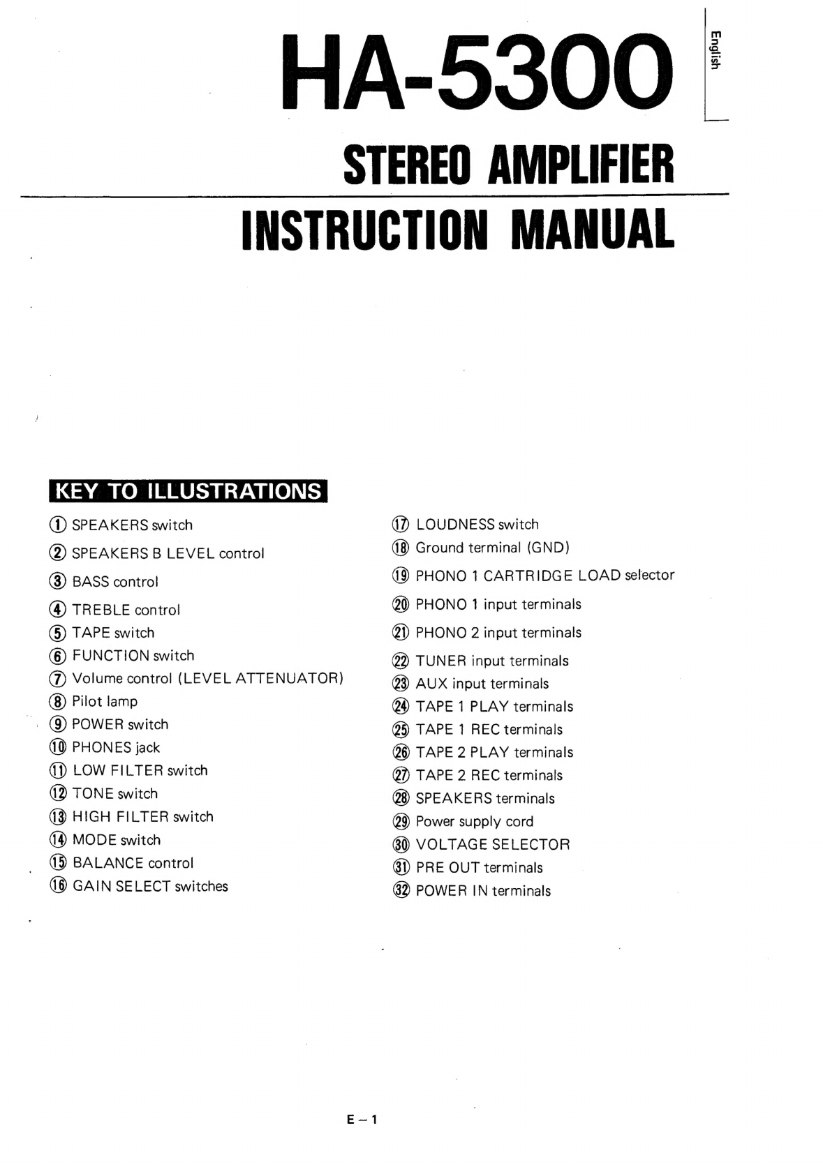
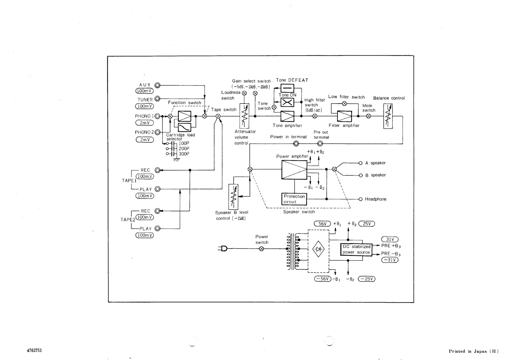
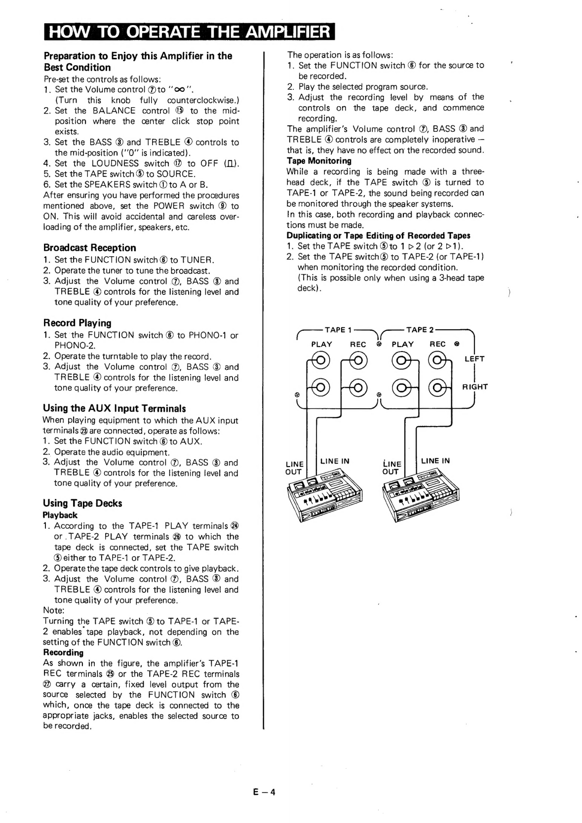
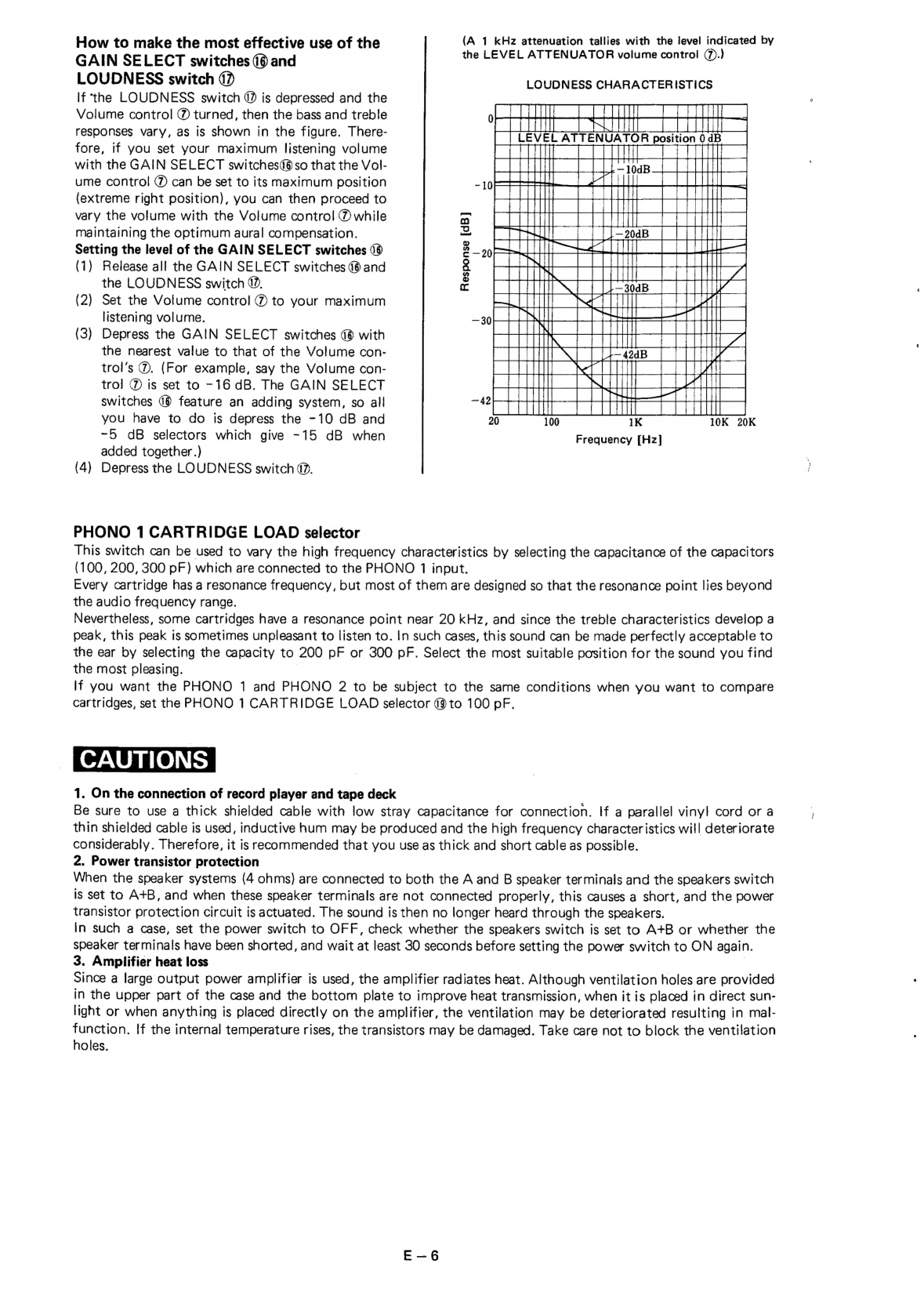
Hitachi HA-5300 User manual

_
HA-5300
STEREO
AMPLIFIER
INSTRUCTION
MANUAL
KEY
TO
ILLUSTRATIONS
(1)
SPEAKERS
switch
(7)
LOUDNESS
switch
@
SPEAKERS
B
LEVEL
control
Ground
terminal
(GND)
®
BASS
contro!
PHONO
1
CARTRIDGE
LOAD
selector
(4)
TREBLE
contro!
20)
PHONO
1
input
terminals
()
TAPE
switch
@)
PHONO
2
input
terminals
@
FUNCTION
switch
22
TUNER
input
terminals
(7)
Volume
control
(LEVEL
ATTENUATOR)
@3)
AUX
input
terminals
—
@
Pilot
lamp
@@)
TAPE
1
PLAY
terminals
_@
POWER
switch
@B)
TAPE
1
REC
terminals
PHONES
jack
6)
TAPE
2
PLAY
terminals
()
LOW
FILTER
switch
@)
TAPE
2
REC
terminals
2
TONE
switch
SPEAKERS
terminals
MODE
switch
VOLTAGE
SELECTOR
13
BALANCE
control
61)
PRE
OUT
terminals
GAIN
SELECT
switches
89
POWER
IN
terminals

4762751
AUX
©
100mV)
TUNER
©
100mV
Ov
omv
PHONO
2©@
amv
fe
REC
©
100mV
TAPE1
Lepay
O}
REC
©
TAPE2N00mV
Lot
ay
O
Gain
select
switch.
Tone
DEFEAT
(—5dB,
—10dB,
-200B
)
a
TT
|
TmEON
|
Low
filter
swi
switch
High
filter
Switch
Balance
control
Function
switch
Tone
switch
)
heda
r
7
(X<)
/
Tape
switch
switch
Eee
|
(64B
/
oct
)
Pua
switch
®
>
3
|
>>
+-8
Tone
amplifier
Filter
amplifier
Attenuator
Pre
out
Galt
eee
load
volume
Power
in
terminal
—
termimal
°
100P
control
O
O
+B,
+Be
O-
”
|
Power
amplifier
©
A
speaker
OQ
B
speaker
Protection
©
Headphone
circuit
Speaker
B
level
Speaker
switch
control
(
—15dB}
+B,
+B,
C25V
f-~—~-
Power
!
switch
Printed
in
Japan
(H)

INSTALLATION
Please
choose
a
place
that
satisfies
the
following
conditions
when
installing
the
HA-5300.
1.
A
place
free
from
direct
sunlight
and
heat
from
a
stove,
etc.
2.
Since
the
HA-5300
incorporates
a
large
output
power
amplifier,
choose
a
well
ventilated,
moisture-free
place.
3.
Install
ona
stable
and
vibration-free
surface.
FEATURES
1.
Dynaharmony
system
perfectly
matched
for
music
reproduction
The
amplifier
features
four
power
supplies
(56
V
high
voltage
and
+25
V
low
voltage
power
supplies).
High-
speed
switching
occurs
between
the
power
supplies
in
accordance
with
the
peak
level
of
the
music
signal.
This
makes
for
a
sufficient
margin
with
respect
to
the
dynamic
range
of
music
signals
and
also
for
an
extremely
high
level
of
efficiency.
2.
Current
mirror
circuit
in
the
Class
A
driver
circuit
The
Class
A
driver
circuit,
which
is
the
very
heart
of
the
main
amplifier,
features
a
current
mirror
circuit
for
push-
pull
drive
in
the
power
stage
and
for
a
low
distortion
factor.
3.
32-contact
attenuator
volume
control
for
an
accurately
adjusted
level
control
With
this
control,
there
is
very
little
deviation
between
the
left
and
right
channels
and
the
attenuation
can
be
controlled
accurately.
4.
Independent
3-stage
adding
gain
selector
for
extended
fine
setting
range
The
~5
dB,-10
dB
and
-20
dB
gain
selectors
each
feature
an
independent
adding
system
and
so
7
different
atten-
uation
variations
can
be
obtained
between
-5
dB
and
-35
dB,
permitting
use
over
a
wide
range.
Also,
the
combi-
nation
of
the
attenuator
volume
contro!
and
the
loudness
switch
makes
for
an
ideal
loudness
response,
and
it
serves
for
presetting,
too.
5.
3-stage
direct-coupled
equalizer
amplifier
composed
of
2
FETs
and
2
transistors
with
differential
amplifier
for
first
stage
The
3-stage
equalizer
amplifier
which
employs
a
differential
amplifier
for
the
first
stage
yields
a
low
distortion
and
a
high
signal-to-noise
ratio
and
features
plenty
to
spare
with
a
350
mVrms
(1
kHz,
0.3%}
maximum
allowable
input.
6.
Easy
listening
comparison
with
speaker
level
control
The
level
of
the
B
speaker
system
can
be
controlled
on
the
front
panel
which
means
that
it is
easy
to
bring
that
level
in
line
with
the
level
of
the
A
speaker
system
for
simple
listening
comparison.
7.
PHONO
input
capacitance
selector
switch
This
switch
can
be
used
to
select
the
PHONO
1
input
capacitance
to
any
of
three
stages.
This
means
that
the
peak
in
the
characteristics
at
the
resonance
point
of
the
cartridge’s
high-end
frequency
(near
20
Ne!
can
be
suppressed
and
that
you
can
listen
to
a
record
with
the
preferred
tone
quality.
8.
Low
filter
that
reduces
hum
and
rumble
in
the
ultra-low
frequencies
without
impairing
the
sound
quality
The
low
filter
employs
a
20
Hz
(12
dB/oct.)
subsonic
filter
which
helps
to
eliminate
undesirable
vibration
in
the
ultra-low
frequencies
without
impairing
the
sound
quality,
and
which
allows
the
speakers
to
function
always
at
their best.
9.
High
filter
that
effectively
cuts
out
noise
produced
from
scratches
on
records
and
high
frequency
noise
during
AM
and
FM
reception
The
high
filter
has
figures
of
8
kHz
(6
dB/oct.)
so
that
it
effectively
cuts
out
high
frequency
noise.
10.
Tone
defeat
switch
for
instant
flat
characteristics
This
switch
can
be
selected
in
a
flash
for
flat
characteristics
regardless
of
the
bass
and
treble
controls.
When
set
to
‘defeat’,
the
signals
do
not
pass
through
the
tone
control
circuit.
11.
Protective
circuitry
for
safety
The
amplifier
incorporates
electronic
protective
circuits
to
protect
both
the
speakers
and
the
power
transistors.
There
is
also
a
muting
circuit
which
helps
to
reduce
shock
noise
when
the
power
switch
is
turned
on
and
off.
ler
Power
(Mains)
Requirements
This
unit
can
be
used
with
a
power
(mains)
voltage
of
120
V,
220
V
or
240
V.
Before
shipment,
it
is
set
for
220
V
or
240
V
according
to
the
region
it
is
to
be
sent
to.
The
power
(mains)
voltage
of
the
unit
is
marked
on
the
rear
panel.
When
the
power
(mains)
voltage
is
different,
please
consult
your
dealer.

IMPORTANT
FOR
U.K.:
WARNING:
This
apparatus
must
be
earthed.
The
wires
in
this
mains
lead
are
coloured
in
accordance
with
the
following
code:
Green
and
Yellow:
EARTH
Blue:
NEUTRAL
Brown:
LIVE
As
the
colours
of
the
wires
in
the
mains
lead
of
this
apparatus
may
not
correspond
with
the
coloured
markings
identifying
the
terminals
in
your
plug
proceed
as
follows.
The
wire
which
is
coloured
GREEN
and
YELLOW
must
be
connected
to
the
terminal
in
the
plug
which
is
marked
by
the
letter
E
or
by
the
safety
earth
symbol
==
or
coloured
GREEN
or
GREEN
and
YELLOW.
The
wire
which
is
coloured
BLUE
must
be
connected
to
the
terminal
which
is
marked
with
the
letter
N
or
coloured
BLACK.
The
wire
which
is
coloured
BROWN
must
be
connected
to
the
terminal
which
is
marked
with
the
letter
L
or
coloured
RED.
CONNECTING
1.
Connection
of
Speakers
Two
sets
of
speaker
systems
(A
and
B)
can
be
connected
to
this
amplifier.
A
performance
of
music
can
be
en-
joyed
using
either
both
speaker
systems
or
only
one
of
them.
As
shown
in
the
figure
on
the
cover
page,
connect
the
terminals
marked
LEFT
to
the
L
ch
speaker
systems.
In
the
same
way,
connect
the
terminals
marked
RIGHT
to
the
R
ch
speaker
systems.
|
Notes:
|
(2)
When
4
ohm
speakers
are
connected
to
both
(1)
As
illustrated
in
the
figure
on
the
cover
page,
A
and
B,
and
the
SPEAKERS
switch
is
set
at
the
upper
terminals
are
for
@
speakers,
and
A
+B,
the
combined
impedance
of
the
speakers
the
lower
terminals
are
for
®
speakers.
The
is
only
2
ohms.
Avoid
using
this
arrangement.
red
terminals
are
the
positive
(+)
ones,
and
the
Be
sure
to
connect
speakers
of
more
than
black
terminals
are
the
negative
(-)
ones.
8
ohms
when
two
sets
of
speakers
are
to
be
Make
sure
to
correspond
the
polarities
of
the
operated
simultaneously.
terminals
in
this
amplifier
to
those
of
the
(3)
Turn
the
SPEAKERS
switch
©
OFF
when
terminals
in
each
speaker.
only
headphones
are
being
used.
2.
Connection
of
Turntable
Connect
the
output
cords
of
the
turntable
to
the
terminals
of
the
amplifier
as
described
below.
Each
connection
is
different
depending
on
the
kind
of
cartridges.
(1)
Moving
magnet
cartridges
(3)
Ceramic
or
crystal
cartridges
Connect
the
output
cords
of
the
turntable
to
Connect
to
the
AUX
input
terminals
@.
the
PHONO-1
@
or
PHONO-2
@)
input
ter-
Note:
minals.
Be
sure
to
connect
a
grounding
wire
from
the
turn-
(2)
Moving
coil
cartridges
table
to
the
GND
termina!
of
the
amplifier,
Connect
to
the
PHONO-1
@
or
PHONO-2
as
shown
in
the
figure
on
the
cover
page.
@
input
terminals
via
a
matching
transform-
Unless
the
connection
of
a
grounding
wire
is
done,
er
or
head
amplifier.
hum
noise
will
come
out
from
the
speakers.
3.
Connection
of
Tape
Decks
Since
two
sets
of
the
record
and
playback
terminals
(8
pin-jacks)
are
provided,
two
tape
deck
connections
are
available
at
the
same
time
and
dubbing
or
duplicate
recordings
from
one
tape
deck
to
the
other
can
be
done.
Connections
with
pin-jacks
(TAPE-1,
TAPE-2)
Connect
the
record
terminals
(LINE
IN)
of
the
the
tape
deck
to
the
TAPE-1
@
or
TAPE-2
@
tape
deck
to
the
TAPE-1
@)
or
TAPE-2
@
REC
PLAY
terminals
of
the
HA-5300.
terminals
and
the
output
terminals
(LINE
OUT)
of
See
the
figure
on
the
cover
page.
4.
Use
of
the
AUX
input
Jacks
These
jacks
@
are
a
set
of
spare
input
jacks.
They
can
be
connected
to
cartridge
tape
players,
television
sound
multiplex
tuners,
or
other
forms
of
signal
output.
The
upper
of
the
two
terminals
is
the
L
(left)
channel,
and
the
lower
is
the
R
(right)
channel.
5.
Use
of
the
PRE
OUT
Jacks
and
the
POWER
IN
Jacks
Use
these
jacks
when
using
the
preamplifier,
or
power
amplifier,
separately.
Connecting
plug
Use
this
plug
to
connect
the
power
amplifier
to
turn
the
switch
on
your
power
amplifier
to
OFF
the
preamplifier.
It
is
usually
kept
connected.
when
you
intend
to
use
the
preamplifier
separately
However,
disconnect
it
when
using
the
preampli-
before
operating
the
power
switch
on
this
ampli-
fier
or
the
power
amplifier
separately.
Always
fier.
E-—3

HOW
TO
OPERATE
THE
AMPLIFIER
Preparation
to
Enjoy
this
Amplifier
in
the
Best
Condition
Pre-set
the
controls
as
follows:
1.
Set
the
Volume
control
@to
‘*co”’,
(Turn
this
knob
fully
counterclockwise.)
2.
Set
the
BALANCE
control
©
to
the
mid-
position
where
the
center
click
stop
point
exists.
3.
Set
the
BASS
®
and
TREBLE
@®
controls
to
the
mid-position
('‘0”
is
indicated).
4.
Set
the
LOUDNESS
switch
42
to
OFF
(Q).
5.
Set
the
TAPE
switch
@
to
SOURCE.
6.
Set
the
SPEAKERS
switch
©
to
A
or
B.
After
ensuring
you
have
performed
the
procedures
mentioned
above,
set
the
POWER
switch
@
to
ON.
This
will
avoid
accidental
and
careless
over-
loading
of
the
amplifier,
speakers,
etc.
Broadcast
Reception
1.
Set
the
FUNCTION
switch
©
to
TUNER.
2.
Operate
the
tuner
to
tune
the
broadcast.
3.
Adjust
the
Volume
control
®,
BASS
@®
and
TREBLE
@®
controls
for
the
listening
level
and
tone
quality
of
your
preference.
Record
Playing
1.
Set
the
FUNCTION
switch
©
to
PHONO-1
or
PHONO-2.
2.
Operate
the
turntable
to
play
the
record.
3.
Adjust
the
Volume
control
®,
BASS
®
and
TREBLE
@
controls
for
the
listening
level
and
tone
quality
of
your
preference.
Using
the
AUX
Input
Terminals
When
playing
equipment
to
which
the
AUX
input
terminals
@
are
connected,
operate
as
follows:
1.
Set
the
FUNCTION
switch
©
to
AUX.
2.
Operate
the
audio
equipment.
3.
Adjust
the
Volume
control
®,
BASS
®
and
TREBLE
@
controls
for
the
listening
tevel
and
tone
quality
of
your
preference.
Using
Tape
Decks
Playback
1.
According
to
the
TAPE-1
PLAY
terminals
@
or
.TAPE-2
PLAY
terminals
@
to
which
the
tape
deck
is
connected,
set
the
TAPE
switch
®
either
to
TAPE-1
or
TAPE-2.
2.
Operate
the
tape
deck
controls
to
give
playback.
3.
Adjust
the
Volume
contro!
®,
BASS
®
and
TREBLE
®
controls
for
the
listening
level
and
tone
quality
of
your
preference.
Note:
.
Turning
the
TAPE
switch
©
to
TAPE-1
or
TAPE-
2
enables
tape
playback,
not
depending
on
the
setting
of
the
FUNCTION
switch
©.
Recording
As
shown
in
the
figure,
the
amplifier’s
TAPE-1
REC
terminals
@
or
the
TAPE-2
REC
terminals
@
carry
a
certain,
fixed
level
output
from
the
source
selected
by
the
FUNCTION
switch
©
which,
once
the
tape
deck
is
connected
to
the
appropriate
jacks,
enables
the
selected
source
to
be
recorded.
The
operation
is
as
follows:
1.
Set
the
FUNCTION
switch
©
for
the
source
to
be
recorded.
2.
Play
the
selected
program
source.
3.
Adjust
the
recording
level
by
means
of
the
controls
on
the
tape
deck,
and
commence
recording.
The
amplifier’s
Volume
control
®,
BASS
@®
and
TREBLE
®
controls
are
completely
inoperative
—
that
is,
they
have
no
effect
om
the
recorded
sound.
Tape
Monitoring
While
a
recording
is
being
made
with
a
three-
head
deck,
if
the
TAPE
switch
©
is
turned
to
TAPE-1
or
TAPE-2,
the
sound
being
recorded
can
be
monitored
through
the
speaker
systems.
In
this
case,
both
recording
and
playback
connec-
tions
must
be
made.
Duplicating
or
Tape
Editing
of
Recorded
Tapes
1.
Set
the
TAPE
switch
©
to
1
>
2
(or
2
D1).
2.
Set
the
TAPE
switch®
to
TAPE-2
(or
TAPE-1)
when
monitoring
the
recorded
condition.
(This
is
possible
only
when
using
a
3-head
tape
deck).
a
ati
Gee

Recording
an
FM
broadcast
or
records
on
one
tape
deck
while
playing
back
a
tape
on
the
other
1.
Connect
both
tape
decks
to
the
amplifier.
2.
Set
the
FUNCTION
switch
©
to
PHONO-1
PHONO-2,
TUNER
or
AUX
in
accordance
with
the
program
source
you
are
about
to
record.
3.
Set
the
TAPE
switch
©
to
the
TAPE
terminals
(TAPE-1
or
TAPE-2)
to
which
ine
playback
tape
deck
is
connected.
4.
Operate
the
playback
tape
deck
and
start
to
play
back
the
tape.
5,
Adjust
the
volume
to
the
desired
level
using
the
Volume
contro!
@.
6.
Operate
the
recording
tape
deck
and
start
recording.
Use
the
level
controls
on
the
tape
deck
to
adjust
the
recording
level.
Operation
Checkpoints
(for
using
tape
decks)
pos
TAPE
switch
©
Sound
from
speakers
Playback
Any
setting
Sound
reproduced
from
tape
deck
connected
to
TAPE-1.
Sound
reproduced
from
tape
deck
connected
to
TAPE-2.
Recording
Set
to
program
source
Sound
from
program
source
selected
by
FUNCTION
switch
©.
Monitoring
recording
Set
to
program
source
Tape
dubbing
|
Any
setting
(1
>2)
-
(2
>
1)
Set
to
program
source
Sound
being
recorded
on
tape
deck-1
can
be
monitored.
Sound
being
recorded
on
tape
deck-2
can
be
monitored.
Sound
recorded
on
tape
deck-1.
Sound
being
recorded
on
tape
deck-2.
Sound
recorded
on
tape
deck-2.
Sound
being
recorded
on
tape
deck-1.
Sound
recorded
on
(playback
)tape
deck-1.
Recording
FM
broadcast
or
records
on
one
tape
deck,
while
playing
back
tape
on
the
other
Sound
recorded
on
(playback)
tape
deck-2.

How
to
make
the
most
effective
use
of
the
GAIN
SELECT
switches
(@
and
LOUDNESS
switch
4?
If
the
LOUDNESS
switch
@
is
depressed
and
the
Volume
control
®
turned,
then
the
bass
and
treble
responses
vary,
as
is
shown
in
the
figure.
There-
fore,
if
you
set
your
maximum
listening
volume
with
the
GAIN
SELECT
switchesd@
so
that
the
Vol-
ume
control
@
can
be
set
to
its
maximum
position
(extreme
right
position),
you
can
then
proceed
to
vary
the
volume
with
the
Volume
control
@
while
my
cE
ee
maintaining
the
optimum
aural
compensation.
=
Pra
|
|
toa
|
TT
Setting
the
level
of
the
GAIN
SELECT
switches
@
Boop
ee
Te
S
LLIN
|
TT
TP
TTT
(
1
)
Release
all
the
GAIN
SELECT
switches
46)
and
G
TT
TIN
TTT
OT:
7
the
LOUDNESS
switch
©.
©
[COIN
E
TE
s00n
TT
(2)
Set
the
Volume
contro!
®
to
your
maximum
pT
Ne
TTT
a
(3)
listening
volume.
Depress
the
GAIN
SELECT
switches
4
with
the
nearest
value
to
that
of
the
Volume
con-
trol’s
@.
(For
example,
say
the
Volume
con-
{A
1
kHz
attenuation
tallies
with
the
level
indicated
by
the
LEVEL
ATTENUATOR
volume
control
(%).)
LOUDNESS
CHARACTERISTICS
ee
a
P
TTT
OT
NA
LEVEL
ATTENUATOR
position
0
dB
2
a
ee
erred
Ee
toes
ae
i
ae
ttt
~10
Pt
PNT
TSS
re
Mn...
TTT
OT
TTT
TT)
TIN
MBRINEE
cnn
FPO
Nee
LL
df
Pt
TN
a
2
trol
@
is
set
to
-16
dB.
The
GAIN
SELECT
;
fea
TT
TAN
a
switches
8
feature
an
adding
system,
so
all
—a2f
+
Let
LL
a
you
have
to
do
is
depress
the
-10
dB
and
20
10K
20K
~5
dB
selectors
which
give
-~15
dB
when
added
together.)
(4)
Depress
the
LOUDNESS
switch
@.
cacti:
a
PHONO
1
CARTRIDGE
LOAD
selector
This
switch
can
be
used
to
vary
the
high
frequency
characteristics
by
selecting
the
capacitance
of
the
capacitors
(100,
200,
300
pF)
which
are
connected
to
the
PHONO
1
input.
Every
cartridge
has
a
resonance
frequency,
but
most
of
them
are
designed
so
that
the
resonance
point
lies
beyond
the
audio
frequency
range.
Nevertheless,
some
cartridges
have
a
resonance
point
near
20
kHz,
and
since
the
treble
characteristics
develop
a
peak,
this
peak
is
sometimes
unpleasant
to
listen
to.
In
such
cases,
this
sound
can
be
made
perfectly
acceptable
to
the
ear
by
selecting
the
capacity
to
200
pF
or
300
pF.
Select
the
most
suitable
position
for the
sound
you
find
the
most
pleasing.
If
you
want
the
PHONO
1
and
PHONO
2
to
be
subject
to
the
same
conditions
when
you
want
to
compare
cartridges,
set
the
PHONO
1
CARTRIDGE
LOAD
selector
(to
100
pF.
CAUTIONS
1.
On
the
connection
of
record
player
and
tape
deck
Be
sure
to
use
a
thick
shielded
cable
with
low
stray
capacitance
for
connection.
If
a
parallel
vinyl
cord
or
a
thin
shielded
cable
is
used,
inductive
hum
may
be
produced
and
the
high
frequency
characteristics
will
deteriorate
considerably.
Therefore,
it
is
recommended
that
you
use
as
thick
and
short cable
as
possible.
2.
Power
transistor
protection
When
the
speaker
systems
(4
ohms)
are
connected
to
both
the
A
and
B
speaker
terminals
and
the
speakers
switch
is
set
to
A+B,
and
when
these
speaker
terminals
are
not
connected
properly,
this
causes
a
short,
and
the
power
transistor
protection
circuit
is
actuated.
The
sound
is
then
no
longer
heard
through
the
speakers.
In
such
a
case,
set
the
power
switch
to
OFF,
check
whether
the
speakers
switch
is
set
to
A+B
or
whether
the
speaker
terminals
have
been
shorted,
and
wait
at
least
30
seconds
before
setting
the
power
switch
to
ON
again.
3.
Amplifier
heat
loss
Since
a
large
output
power
amplifier
is
used,
the
amplifier
radiates
heat.
Although
ventilation
holes
are
provided
in
the
upper
part
of
the
case
and
the
bottom
plate
to
improve
heat
transmission,
when
it
is
placed
in
direct
sun-
light
or
when
anything
is
placed
directly
on
the
amplifier,
the
ventilation
may
be
deteriorated
resulting
in
mal-
function.
If
the
internal
temperature
rises,
the
transistors
may
be
damaged.
Take
care
not
to
block
the
ventilation
holes.

SPECIFICATIONS
Power
amplifier
Circuitry
Dynamic
power
Output
RMS
power
(both
channels
driven)
Power
bandwidth
‘
Total
harmonic
distortion
(1
kHz,
8
ohms
load)
Intermodulation
distortion
(60
Hz:
7
kHz
=4:1)
Damping
factor
Output
terminal
Speaker
level
control
Input
sensitivity
(impedance)
Preamplifier
Circultry
Input
sensitivity
(Impedance)
Phono
overload
level
Output
terminal
(level
/impedance)
Frequency
characteristics
Tone
contro]
Filter
Loudness
control
(volume
—30
dB)
Signal-to-noise
ratio
(IHF,
A
network)
Gain
selector
Power
supply,
others
Semi-conductors
Power
supply
Power
consumption
Dimensions
Weight
2-stage
differential
all-stage
direct-coupled
4-power
supply
high-
efficiency
pure
complementay
OCL
system
(Dynaharmony
system)
260
W
(IHF
8
ohms)
60
watts
per
channel,
min.
RMS,
at
8
ohms
from
20
Hz
to
20
kHz,
with
no
more
than
0.3%
total
harmonic
distortion.
75W/cht+75W/ch
(8
ohms,
1
kHz,
T.H.D.
0.3%)
85
W
/ch
+85
W/ch
(4
ohms,
1
kHz,
T.H.D.
0.3%)
10
Hz
-
50
kHz
0.05%
(at
rated
output)
0.05%
(at
1/2
rated
output)
More
than
40
Speaker
terminal
:
A,B
(4
-
16
ohms),
A+B
(8
-
16
ohms)
Headphone
terminal:
More
than
4
ohms
B
level
is
variable
-15
dB
1.0
V
(55
k
ohms)
Equalizer
amp.:
Differential
1-stage,
3-stage
directly
coupled
Control
amp.:
NF
type
PHONO
1,2
:
2
mV
(50
k
ohms)
TUNER,
AUX
:
100
mV
(50
k
ohms)
TAPE
1,2
:
100
mV
(50
k
ohms)
PHONO
1,2
:
350
mV
(at
1
kHz,
T.H.D.
0.3%)
TAPE
1,2
REC
OUT
:
100
mV
/
1k
ohms
PHONO
:
30
—
15,000
Hz
(RIAA
+0.2
dB)
TUNER,
AUX
:
10
Hz
—
50
kHz
(+9
dB)
BASS
:
+8
dB
(100
Hz)
TREBLE
:
+8
dB
(10
kHz)
LOW
:
20
Hz
(12
dB/oct.)
HIGH
:
8
kHz
(6
dB/oct.)
+8
dB
(100Hz)
+4.5dB
(10
kHz)
PHONO
1,2
:
75
dB
TUNER,
AUX,
TAPE
1,2
:
90
dB
~5,-10,-20
dB
(addition
type)
6
FETs,
44
Transistors,
43
Diodes
~120
V
/220V/240V
50/60
Hz
500
W
(at
rated
output)
435
(W)
x
166.5
(H)
x
391
(D)
mm
(Measuring
from
front
knob
to
rear.)
12.3
kg
(27
.1
Ibs.)

HA-5300
This
set
is
available
also
with
front
panels
in
different
colors.
@)
HITACHI
Cet
appareil
est
également
disponible
avec
un
panneau
frontal
de
couleur
différente.
Dieses
Gerdt
ist
ebenfalls
mit
einer
Frontseite
in
anderer
Farbe
erhdltlich.
Denna
enhet
finns
tillganglig
med
frontpaneler
i
flera
olika
farger.
AM/FM
STEREO
TUNER
UKW/AM
STEREO-TUNER
TUNER
STEREO
AM/FM
AM/FM
STEREOMOTTAGARE
anes
ae
FEY
os
i@©
anal
ee
ee
|
PRE
-
POWER
:
4
c
PRE
OUT
POWER
IN
J
S
:
ohm
L
&,
8
--
Hau
t
de
a
16
ofrms
lf
you
want
to
change-over
the
set
voltage
from
220V
or
240V
to
120V,
the
primary
fuse
must
also
be
changed.
Please
contact
the
dealer
from
whom
you
purchased’
this
unit
or
your
nearest
HITACHI
service
station.
Beim
Umschalten
der
Spannungseinstellung
von
220V
oder
240V
auf
120V
mu
auch
die
Hauptsicherung
ausgewechselt
werden.
Uberlassen
Sie
diese
Arbeit
bitte
dem
Fach-
handler,
von
dem
Sie
das
Geraét
erworben
haben,
oder
Ihrer
nachsten
HITACHI-
Kundendienststelle.
Si
l'on
veut
changer
la
tension
de
220V
ou
240V
a
120V,
il
faut
également
changer
le
fusible
primaire.
Prendre
contact
‘ec
le
distributeur
qui
a
vendu
|’
appareil
ou
avec
la
station
service
HITACHI
la
plus
—
dche.
Skall
enhetens
natspanning
bytas
fran
220V
eller
240V
till
120V
maste
huvudsdkringen
ocksa
bytas.
Radfraga
stereohanceln
dar
enheten
kdptes
eller
narmaste
HITACHI
serviceavdelning.
A+B
—
Hav
5
4B
ons
VOLTAGE
SELECTOR
i
ae
(deme
>
oo
a
2200.
240V~
;
INPUT
:
TAPE
TAPES
CARTRIDGE
LOAD
PHONG
1
PHONG
TIPNER
AUX
PLAY
REC
PLAY
REC
“
pF
100
—
200
~
Earth
wire
Erdung
Fil
de
prise
de
terre
Jordkabel
BANDSPELARE
STEREO
AM
PL
IF
ODEL
No.
HA
—
WatTTs
Hitachi,
Ltd.
Tok
a.
(4401451)
*
FI
ill
|
TURNTABLE
TAPE
DECK
SPEAKER
SYSTEM
PLATTENSPIELER
TONBANDGERAT
LAUTSPRECHERGRUPPE
TOURNE-DISQUE
MAGNE
TOPHONE
HAUT-PARLEURS
SKIVSPELARE
HOGTALARE

Sta
oa
Spgs
a
a
Ree
Pear
Ne
SE
See
ree
ary
ow
cr
aa
aren
mm
rae
arm
peayme
cm
pagename
Se
A
a
H
—————————$
$$
Ss
er.
_
|)
TT
A-5300
HITACH!
SALES
EUROPA
GmbH
2
Hamburg
54,
Kleine
Bahn
Strasse
8,
West
Germany
Tel.:
850
60
71-75
HITACHI
SALES
(U.K.)
Ltd.
Hitachi
House,
Station
Road,
Hayes,
Middlesex
UB3
4DR,
England
Tel.:
01-848-8787
:
HITACHI!
SALES
SCANDINAVIA
AB
Rissneleden
8,
Sundbyberg,
Box
7138,
S-172-07
Sundbyberg
7,
Sweden
Tel.:
08-98
52
80
HITACHI
SALES
A.G.
5600
Lenzburg,
Switzerland
Tel.:
064-513621
HITACHI-FRANCE
(Radio-T
élévision
Electro-Ménager)
S.A.
9,
Boulevard
Ney,
75018,
Paris
Tel.:
23-25-00
iy
©
HITACHI
Table of contents
Other Hitachi Amplifier manuals

Hitachi
Hitachi HMA-8300 User manual

Hitachi
Hitachi HA-M33 User manual

Hitachi
Hitachi HMA-6500 User manual

Hitachi
Hitachi HCA-6500 User manual

Hitachi
Hitachi HA-3700 User manual

Hitachi
Hitachi HCA-7500 User manual

Hitachi
Hitachi HA-M44 User manual

Hitachi
Hitachi HA-7700 User manual

Hitachi
Hitachi IA-1200 User manual

Hitachi
Hitachi HMA-7500 User manual

Hitachi
Hitachi HA-6800 User manual

Hitachi
Hitachi HA-5700 User manual

Hitachi
Hitachi HA-330 User manual

Hitachi
Hitachi HA-2800 User manual

Hitachi
Hitachi HA-7700 User manual

Hitachi
Hitachi HTA-12 User manual

Hitachi
Hitachi HTA-4000 User manual

Hitachi
Hitachi HA-3800 User manual

Hitachi
Hitachi HCA-8300 User manual

Hitachi
Hitachi HCA-8500Mk2 User manual