manuals.online logo
Brands
  1. Home
  2. •
  3. Brands
  4. •
  5. Hitachi
  6. •
  7. Controllers
  8. •
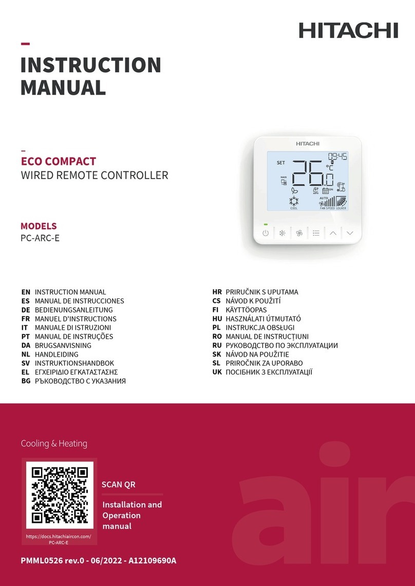
  9. Hitachi HCWA10NEGQ User manual

Hitachi HCWA10NEGQ User manual

Operation Steps
Operation Steps
Operation Steps
Operation Steps
Operation Steps
Safety Precautions:
Figure 1 shows all the indications for reference. The actual display during operation is different(All figures in this manual
are only for reference, please refer to the product for the actual display).
1) Key area icons illustration
2) Display area icons illustration
Press any key to light up the backlight.
If unit operation is stopped,wired controller displays mode, communication, fan speed, weekday, time, operating
mark as shown in figure 2.
Press key ① to start the operation, wired controller displays temperature, wind etc. as shown in figure 3.
If unit operation is start,press key ① to stop the operation as shown in figure 2.
● Do not operate the wired controller by wet hands to avoid electric shock.
● Do not wash the wired controller by water to avoid electric shock or fire.
● Do not mount the wired controller in a humid environment to avoid damage to the internal elements of the controller
due to moisture penetration.
● Do not install the wired control device in the damp environment, avoid to damage the components.
In general circumstances, the wired controller's panel is under screen protection state with dim backlight if there is
no operation. To enable any operation to the wired controller, it's required to first quit the screen protection state
(press any key to light up the backlight) and then enter the operation state.
Touch Screen Wired Controller (Model: HCWA10NEGQ)
1. Product Information
2. Operations of Basic Functions
2.1 ON/OFF
2.2 Regulation of Operation Mode, Fan Speed and Temperature
2.3 Louver Direction
2.4 Individual Louver Setting
2.5 Time Setting
Press any key to light up the backlight
If unit operation is start,press key ② to switch the mode,as shown in
figure 4.
The switching sequence of operating mode: cooling-heating - dry -
ventilation - cooling
Press key ③ to adjust the fan speed. The switching sequence of fan speed:
low - medium - high - ultrahigh - auto - low
Press key ⑤, the temperature increases by 0.5ºC. The range of cooling
temperature regulation is 19ºC to 30ºC and the range of heating
temperature regulation is 17ºC to 30ºC
Press key ⑥, the temperature decreases by 0.5ºC. The range of cooling
temperature regulation is 19ºC to 30ºC and the range of heating
temperature regulation is 17ºC to 30ºC
(See key serial numbers in the panel key description on the home page, for
key ① to key ⑥ from left to right.)
(See key serial numbers in the panel key description on the home page, for
key ① to key ⑥ from left to right.)
1) Press any key to light up the backlight.
2) If unit operation is start, press and hold key ⑤ for 5 s to enter the
louver angle adjustment interface,as shown in figure5.
3) Press and hold key ⑤ and key ⑥ for 5 s to enter the individual angle
setting interface, as shown in Figure 8, and the temperature zone
displays the louver NO.
4) Press key ⑥ to select the louver number.
5) Press key ⑤ to select the louver angle.
6) Press key ③ to confirm and return to the normal operation interface.
(See key serial numbers in the panel key description on the home page, for
key ① to key ⑥ from left to right.)
Operation Steps
1) Press any key to light up the backlight.
2) If unit operation is start, press key ⑤ for 5s to enter the automatic louver mode.
3) And press key ⑤ and key ⑥ for 5s to enter the individual louver adjustment interface, as shown in figure 6.
4) Press key ⑤ or key ⑥ to select the specific indoor unit.
5) Press key ③ for confirmation.
6) Press key ⑥ to select the louver number, as shown in figure 7.
7) Press key ⑤ to select the louver angle.
8) Press key ③ to confirm and return to the normal operation interface .
Press any key to light up the backlight.
Press and hold key ④ and ⑤ 5s to enter the time setting interface, as shown in Figure 9.
Promptly press key ⑤ or ⑥ to set the year, and for example, 2017 is shown in the figure.
Promptly press key ③ to confirm the setting and enter the month setting interface, as shown in Figure 10.
Promptly press key ⑤ or ⑥ to set the month and for example, July is shown in the figure.
Promptly press key ③ to confirm the setting and enter the day setting interface, as shown in Figure 11.
Promptly press key ⑤ or ⑥ to set the day, and for example, 17 is shown in the figure.
Promptly press key ③ for confirm and enter the hour setting interface, as shown in Figure 12.
Promptly press key ⑤ or ⑥ to set the hour, and for example, 17:00 is shown in the figure.
TIPS:
● The minimal step to setting temperature is 0.5ºC or 1ºC and the default value is 0.5ºC.
● By changing the function selection "P1""P2" to select the temperature step and unit(℃ /℉ ) , refer to the chapter:
"function selection" in Installation&Maintenance Manual for the details
● The mode and fan speed identifiable by the wired controller is dependent on the indoor unit model. Different models of
indoor units have a varied control of mode and fan speed. Please consult the local distributor for more details
TIPS:
● Activating the swing louver can orientate the wind direction to improve the level of comfort.
● Louver function is only support the indoor unit which has this function.
When the wired controller controls multiple indoor units, the steps to adjusting the individual
swing Louver angle are as follows:
Function
ON/OFF This key is used to start/stop the equipment
Promptly press this key to switch mode
Promptly press this key to switch fan speed
Promptly press this key to set schedule timer
Press this key to increase temperature, time,
swing louver angle, etc.
Press this key to decrease temperature, time, etc.
Mode
Fan speed
Timer
Up
Down
IllustrationKey No. Icons
Press any key to light up the backlight.
Under operation started status, press and hold key ⑤ for 5s to activate the
swing louver function and enter the automatic swing louver mode, as
shown in figure 5 . The default regulating sequence of cooling angle:
auto , stage 1 , stage 2 , stage 3 , stage 4 , stage 5 and
auto . The default regulating sequence of heating angle:
auto , stage 1 , stage 2 , stage 3 , stage 4 , stage 5 ,
stage 6 , stage 7 and auto
Press key ⑤ shortly to select the desired angle and press key ① shortly or
press and hold key ⑤ to return to the operation interface.
Operation Manual
②
③
④
⑤
①
⑥
1.
When the wired controller controls one indoor unit, the steps to adjusting the individual swing
louver angle are as follows:
2.
1)
2)
3)
4)
5)
1)
2)
3)
1)
2)
3)
1)
2)
3)
4)
5)
Display Area
Key Area
Figure 1
Figure 4
Figure 5
Figure 6
Figure 8
Figure 9 Figure 10
Figure 7
Figure 2 Figure 3
Louver NO.
System
number
Louver NO.
Automatic
Cooling
Heating
Ventilation
Dry
Room temperature
Setting temperature
Centigrade degree
Fahrenheit degree
Timer Time, address and
parameters display
Horizontal louver
Fan speed
Communication
Lock
Defrosting
Alarm
Remote control Lock
Operating mark
IllustrationIcons IllustrationIcons
Indoor Unit
Index Indoor Unit
Address no.
Operation Steps
Operation Steps
Operation Steps
Operation Steps
Operation Steps
2.6 Filter Cleaning Prompt Function
2.8 Lock
2.9 Priority Setting
2.10 Alarm Messages
2.7 Timer Function
Operation Steps
On the wired controller's operation interface, simultaneously press key
② ④ ⑥ for 5 s to activate the wired controller's lock. Then, the
operation interface will display the lock sign, while all function keys will
become invalid, as shown in figure 19
Simultaneously press key ② ④ ⑥ for 5 s. Lock will be deactivated, and
the sign will disappear
Promptly press key ③ to confirm the setting and enter the minute setting interface, as shown in Figure 13.
Promptly press key ⑤ or ⑥ to set the minute, and for example, 17 shown in the figure.
Promptly press key ③ to confirm and return to the operation interface upon successful settings.
(See serial numbers of the keys in the panel key description on the home page, for key ① to ⑥ from left to right.)
When the filter of any indoor unit connected to wired controller in the system should be cleaned, the operation
interface blinks and displays the operating mark as shown in figure 14 . Press key ⑤ and key ⑥ simultaneously
for 5s, the operating mark will stop blinking and the timer for cleaning will be restarted.
(See serial numbers of the keys in the panel key description on the home page, for key ① to ⑥ from left to right.)
1) Press any key to light up the backlight.
2) Promptly press key ④ to enter the timing setting function, as shown in figure 15(If Time ON has setted, press
key① to cancel Time ON), and the interface displays the time on sign with the default time at 00:00, and the
hour value is blinking with a setting range of 0-12 hours.
3) Promptly press key ⑤ to increase the value by 1, and press and hold key ⑤ to increase the value by 5.
Promptly press key ⑥ to reduce the value by 1, and press and hold key ⑤ to reduce the value by 5.
4) Promptly press key ② to switch to the minute setting, with the timing range of 0-59 minutes.
5) Promptly press key ⑤ to increase the value by 1, and press and hold key ⑤ to increase the value by 5.
Promptly press key ⑥ to reduce the value by 1, and press and hold key ⑥ to reduce the value by 5.
6) Promptly press key ③ to select OFF, and promptly press key ① to cancel time off.
7) Promptly press key ② to switch the timing mode: One-off timing (ONCE), daily timing (DAILY), weekly timing
(WEEKLY).
8) Promptly press key ③ to confirm one-off timing (or daily timing), and return to the operation interface. Upon
successful setting, the operation interface displays the ON ONCE (or DAILY) icon, as shown in Figure 16.
9) If it's weekly timing in step 8), press key ② to switch the setting of Sunday to Saturday, promptly press key ① to
cancel the setting, and promptly press key ③ to confirm the setting. Upon successful setting, the operation
interface displays the ON WEEKLY icon.
(See serial numbers of the keys in the panel key description on the home page, for key ① to ⑥ from left to
right.)
1) Press any key to light up the backlight.
2) Promptly press key ④ to enter the timing setting interface, and it displays the timing validation sign.
Promptly press key ① t o cancel TIME ON and confirm TIME OFF(If Time OFF has setted, press key① to
cancel Time OFF), as shown in figure 17. The time zone’s hour value blinks with a setting range of 0-12 hours.
3) promptly press key ⑤ to increase the value by 1, and press and hold key ⑤ to increase the value by 5.
Promptly press key ⑥ to reduce the value by 1, and hold key ⑤ to reduce the value by 5
4) Promptly press key ② to switch to the minute setting, with the timing range of 0-59 minutes.
5) Promptly press key ⑤ to increase the value by 1, and press and hold key ⑤ to increase the value by 5.
Promptly press key ⑥ to reduce the value by 1, and hold key ⑥ to reduce the value by 5.
6) Promptly press key ③ to confirm and enter the timing mode.
Promptly press key ② to switch the timing mode: One-off timing (ONCE), daily timing (DAILY), weekly
timing (WEEKLY).
7) Promptly press key ③ to confirm one-off timing and return to the operation interface. Upon successful
setting, the operation interface displays the OFF ONCE icon, as shown in Figure 18.
8) If it's weekly timing in step 7), press key ② to switch the setting of Sunday to Saturday, promptly
press key ① to cancel the setting, and promptly press key ③ to confirm the setting. Upon successful
setting, the operation interface displays the ON WEEKLY icon.
(See serial numbers of the keys in the panel key description on the home page, for key ① to ⑥ from left to right).
1) Press any key to light up the backlight.
2) If operation is stop, press the key ③ and key ④ for 5 s to enter the priority setting interface, as shown in figure 20.
3) Press key ⑤ or key ⑥, select 01 or02, and set high priority for this wired controller. 00 indicates cancel priority setting ,01
indicates priority setting of operation mode, 02 indicates priority setting of operation mode and setting temperature.
(The priority setting of operation mode means the sub wired controller can only set the specified mode after the main
controller sets operation mode, and refer to the table below for the setting mode. The priority setting of operation mode
and setting temperature means that the sub wired controller can only set the specified mode after the main controller sets
operation mode. After the main controller sets the temperature, the sub wired controller will automatically synchronize to
the same temperature.)
(See serial numbers of the keys in the panel key description on the home page, for key ① to ⑥ from left to right.)
1) Press any key to light up the backlight.
2) Press and hold key ⑥ for 5s to enter the alarm query interface, as shown in figure 23.
3) Promptly press key ⑤ or key ⑥ to browse the alarm.
4) Press the key ① or long press the key ⑥ for 5s to exit the alarm query interface and return to the operation interface.
1) Press any key to light up the backlight.
2) Press and hold key ⑥ for 5 s to enter the alarm query interface.
3) Press and hold key ③ and key ④ for 5 s to delete all alarm records, as shown in figure24.
In case of no alarm, the alarm record displays 00, and the minute area displays 00.
4) Press the key ① or long press the key ⑥ for 5 seconds to exit the alarm query interface and return to the operation interface.
The operations of query are similar with the timing setting operations, i.e., when you have finished the above operations
and enter the timing setting interface again, it will display the timing which was set the last time.
The wired controller with high priority is the main controller, which can limit the operation mode of the sub
wired controller and determine the setting temperature of the sub wired controller. The user can set the main
and sub wired controller freely by changing the priority of the wired controller.
If there is no main controller in a system, the system will automatically specify a main
controller after power on, but the priority will not be set up. If users want to set up a main
controller with high priority, the setting can be made based on the following method:
1. Set [Time ON]
2. Set [Time OFF]
3. [Timing Query]
1. Alarm Query
2. Alarm deletion
TIPS:
● If TIME ON and TIME OFF are both set, then the operation interface will display ON and OFF upon successful settings.
If only TIME ON is set, the operation interface will display ON upon successful setting. If only TIME OFF is set, then the
operation interface will display OFF upon successful settings.
TIPS:
● 30 alarm messages can be recorded at most in the wired controller alarm query.
TIPS:
● After starting the lock, any keypad in the keypad area is invalid
(except for lock hot key), and only the backlight can be lit.
(See serial numbers of the keys in the panel key description on the
home page, for key ① to ⑥ from left to right)
Main controller mode
Cooling
Heating
Ventilation
Dry
Automatic
Setting mode of the sub wired controller
Cooling, dry, ventilation
Heating and ventilation
Ventilation
Cooling, dry, ventilation
Unlimited
6)
7)
1.
1)
2)
4) Press the key ③ for confirmation, and return to the operation interface.
Figure 11 Figure 12
Figure 19
Figure 20 Figure 21
Figure 23 Figure 24
Figure 13 Figure 14
Figure 15 Figure 16
Figure 17 Figure 18
Alarm code Indoor unit
address NO. Alarm NO.
Operation Steps
Press any key to light up the backlight.
In case of operation is stopped, press key ③ and key ④ for 5 s, to
enter the seizing the setting interface of the main controller, as
shown in figure 21. No operation is supported in this interface.
After successful seizure (10 seconds), it will automatically jump
into the priority settings interface, as shown in figure 20.
Press key ⑤ or key ⑥, select 01 or 02,and set high priority for this
wired controller.
00 indicates cancel priority setting ,
01 indicates priority setting of operation mode,
02 indicates priority setting of operation mode
and setting temperature.
Press the key ③ for confirmation, and return to the operation
interface.
On the operation interface, the sub wired controller displays
and the main controller does not display this icon, as shown in
figure 22, which is the operation interface of the sub wired
controller.
(See serial numbers of the keys in the panel key description on the home page, for key ① to ⑥ from left to right.)
TIPS:
● The priority settings are only performed when operation is stopped.
● The priority settings are dependent on the indoor unit model, and the main-sub settings are not supported in
individual cases. Please consult the local distributor for more details.
If there are other main controllers inside the system already, users can set up according to the
method below if want to assign a new main controller:
2.
1)
2)
3)
4)
Figure 22

Other Hitachi Controllers manuals

Hitachi HIDIC EH-150 Instructions for use

Hitachi

Hitachi HIDIC EH-150 Instructions for use

Hitachi Eco Compact PC-ARC-A User manual

Hitachi

Hitachi Eco Compact PC-ARC-A User manual

Hitachi S10mini LQS070 User manual

Hitachi

Hitachi S10mini LQS070 User manual

Hitachi LQZ700 User manual

Hitachi

Hitachi LQZ700 User manual

Hitachi S10mini LQS070 User manual

Hitachi

Hitachi S10mini LQS070 User manual

Hitachi EH-150 Series User manual

Hitachi

Hitachi EH-150 Series User manual

Hitachi HARC-MODBUS User manual

Hitachi

Hitachi HARC-MODBUS User manual

Hitachi HIDIC EH150 EN-TRMME Instructions for use

Hitachi

Hitachi HIDIC EH150 EN-TRMME Instructions for use

Hitachi PSC-A64S User manual

Hitachi

Hitachi PSC-A64S User manual

Hitachi SJ-P1 Series User manual

Hitachi

Hitachi SJ-P1 Series User manual

Hitachi EH-150 Series Instructions for use

Hitachi

Hitachi EH-150 Series Instructions for use

Hitachi EH-150 Type I Instructions for use

Hitachi

Hitachi EH-150 Type I Instructions for use

Hitachi HF-W100E/IoT User manual

Hitachi

Hitachi HF-W100E/IoT User manual

Hitachi ATW-YCC-03 User manual

Hitachi

Hitachi ATW-YCC-03 User manual

Hitachi Eco Compact PC-ARC-A Instruction Manual

Hitachi

Hitachi Eco Compact PC-ARC-A Instruction Manual

Hitachi HD64465 User manual

Hitachi

Hitachi HD64465 User manual

Hitachi HIDIC MICRO-EH Instructions for use

Hitachi

Hitachi HIDIC MICRO-EH Instructions for use

Hitachi HCWA21NEWH User manual

Hitachi

Hitachi HCWA21NEWH User manual

Hitachi PSC-A16RS User manual

Hitachi

Hitachi PSC-A16RS User manual

Hitachi SJ300 Series User manual

Hitachi

Hitachi SJ300 Series User manual

Hitachi CMU Series User manual

Hitachi

Hitachi CMU Series User manual

Hitachi S10VE User manual

Hitachi

Hitachi S10VE User manual

Hitachi H8/3637 User manual

Hitachi

Hitachi H8/3637 User manual

Hitachi MICRO EH H Series User manual

Hitachi

Hitachi MICRO EH H Series User manual

Popular Controllers manuals by other brands

Advantech AMAX-5580 user manual

Advantech

Advantech AMAX-5580 user manual

Inova Automation NICE1000+ user manual

Inova Automation

Inova Automation NICE1000+ user manual

Exlar EL120 Installation and service manual

Exlar

Exlar EL120 Installation and service manual

LEGRAND ADMHRM4 installation instructions

LEGRAND

LEGRAND ADMHRM4 installation instructions

Emotiontek MCU 2 Axis user manual

Emotiontek

Emotiontek MCU 2 Axis user manual

MPS EV2681B-S-00A manual

MPS

MPS EV2681B-S-00A manual

TURBO RACING TB-60080 manual

TURBO RACING

TURBO RACING TB-60080 manual

RealSimulator FSSB-R3 Lighting user guide

RealSimulator

RealSimulator FSSB-R3 Lighting user guide

Belimo AFRB24-MFT N4H manual

Belimo

Belimo AFRB24-MFT N4H manual

Resol deltasol bx plus manual

Resol

Resol deltasol bx plus manual

GE Masoneilan 12400 Series instruction manual

GE

GE Masoneilan 12400 Series instruction manual

National Instruments SB-GPIB Getting started

National Instruments

National Instruments SB-GPIB Getting started

Enterasys C5110 quick reference

Enterasys

Enterasys C5110 quick reference

Vimar Eikon 20594.0 manual

Vimar

Vimar Eikon 20594.0 manual

Moeller PS 4-300 Series Hardware and engineering

Moeller

Moeller PS 4-300 Series Hardware and engineering

Tech Controllers EU-R-8bw user manual

Tech Controllers

Tech Controllers EU-R-8bw user manual

Nico Technology 1201L-1K RTD user manual

Nico Technology

Nico Technology 1201L-1K RTD user manual

Savant CPT-1212 Quick reference guide

Savant

Savant CPT-1212 Quick reference guide

manuals.online logo
manuals.online logoBrands
  • About & Mission
  • Contact us
  • Privacy Policy
  • Terms and Conditions

Copyright 2025 Manuals.Online. All Rights Reserved.