TK
No.
1526E
D-EIO
HITACHI
™
SERVICE
MANUAL
(U,
C,
FS,
BS,
AU,
W)
CONTENTS
DPOCINICAU
ON
Sirsseticanieecedentacascstesutdon
tastes
ntineeecctesst
2
DISASSO
NI
DIV.
scerscesiconn
tsdterashiatinersteoeteeeaestenceds
ds
jee
PCUISUIMCIY
sediasesnscceacosty
date
hsdsGeeduldes
annular
3
Inspection
of
mechanism...
ee
cceeeeeeeeeee
4
LUDIICAMON
so
iscacteceiostatatiagaiate
boven
tesla
eae:
4
Schematic
diagram...
cesscescesseccesseseeseceeees
5
Circuit
board
diagram...
ccc
eeeecsccesscccsseecessees
7
Exploded
view(Cassette
Chassis).......0...0
cee
eeeeee
10
Exploded
view
(Cabinet)
ou...
eecceseccceeesseecees
11
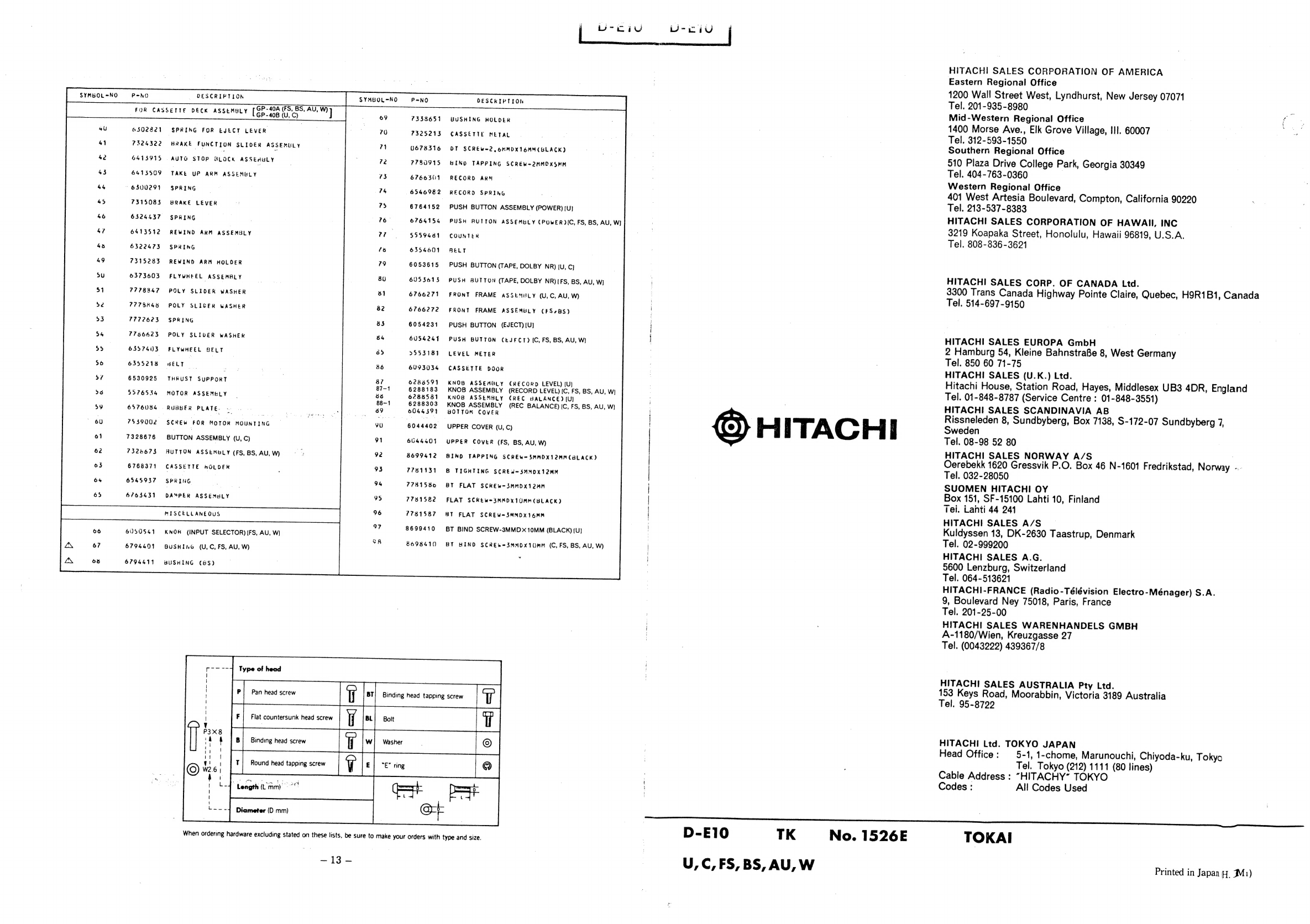
Replacement
parts
list...
ce
cceeecessecesreeeeees
12
KEY
TO
ILLUSTRATIONS
1.
Power
(Mains)
switch
9,
Dolby
NR
switch
2.
Tape
counter
10.
Eject
button
3.
VU
meters
11.
Pause
button
4.
Recording
balance
control
12.
Stop
button
5,
Recording
level
control
13.
Fast
forward
button
6.
Headphone
socket
14.
Playback
button
7.
Microphone
sockets
15.
Rewind
button
8.
Tape
select
switches
|
16.
Record
button
SAFETY
PRECAUTION
The
following
precautions
should
be
observed
when
servicing.
1.
Since
many
parts
in
the
unit
have
special
safety
related
characteristics,
always
use
genuine
Hitachi's
replacement
:
Parts.
Especially
critical
parts
in
the
power
circuit
block
should
not
be
replaced
with
other
makes.
Critical
parts
are
marked
with
A\
in
the
schematic
diagram
and
circuit
board
diagram.
2.
Before
returning
a
repaired
unit
to
the
customer,
the
service
technician
must
thoroughly
test
the
unit
to
ascertain
©
that
it
is
completely
safe
to
operate
without
danger
of
electrical
shock.
SPECIFICATIONS
AND
PARTS
ARE
SUBJECT
TO
CHANGE
FOR
IMPROVEMENT
STEREO
CASSETTE
TAPE
DECK


 User manual")