Tk
||
Ne.
1445e
D-E25
©)
HITACHI
(U,
C,
FS,
BS,
AU,
W)
SERVICE
MANUAL
Use
this
manual
together
with
the
ML-1
mechanism
Technical
Information
(No.1473).
HITA-00383
©
@
®@
©
®
CONTENTS
SPECI
CATIONS
oes
ccsscccesesssesececawersssoesconentedieisnstanedsvarn’
2
DiSASSOMDIY
..............ccessssssenssressccesassassensateseeanoeereneres
2
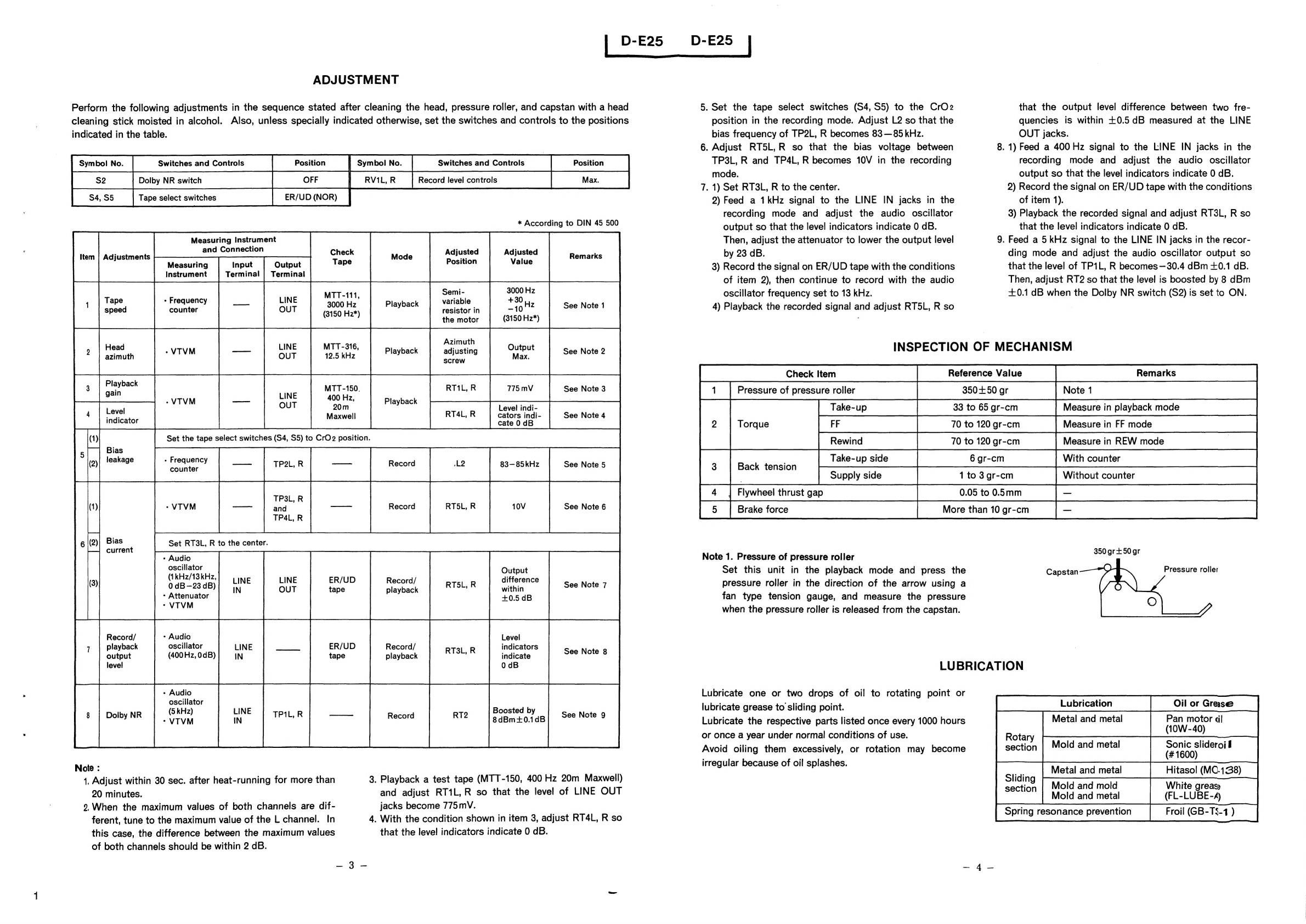
AGIUSTMOGNT
saisdicsmdecepcavensetreicciemste
nie
ent
3
Inspection
of
MEChHANISM...........
cc
seeeteecreeteeeenes
4
EUs
DPiGAtlOM
ssc.
ce,
chcssaccsbsxcctac
Gv
aadaaturtuadoristeenceee
teas
4
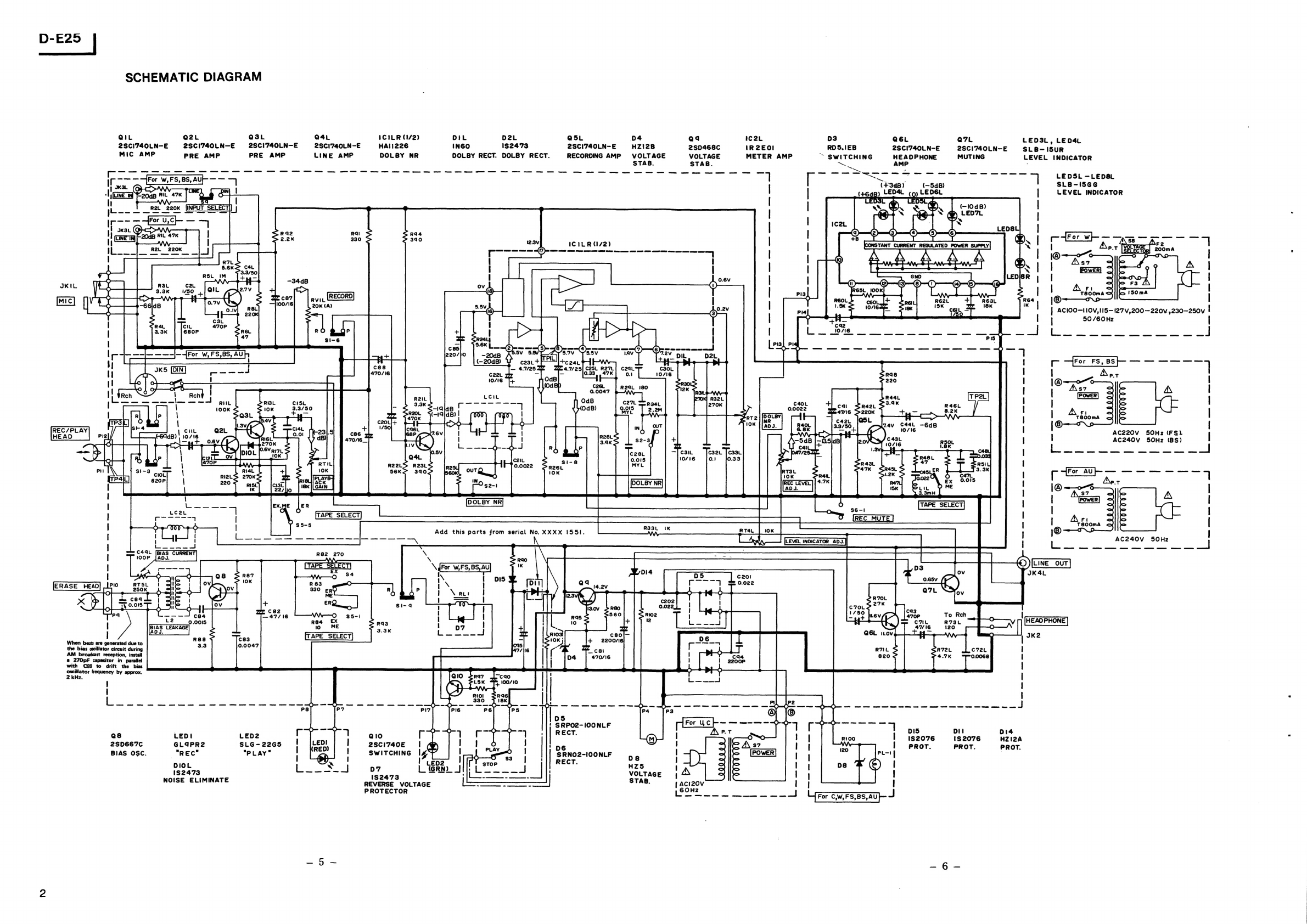
Schematic
diagram
...........cccssecsesssseecetessnecneceenerees
5
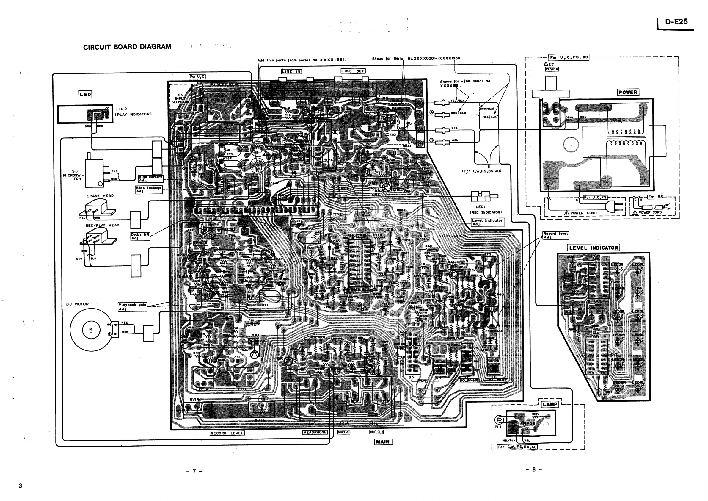
Circuit
board
diagram...........ceceesssececeeeeneaeeeneens
7
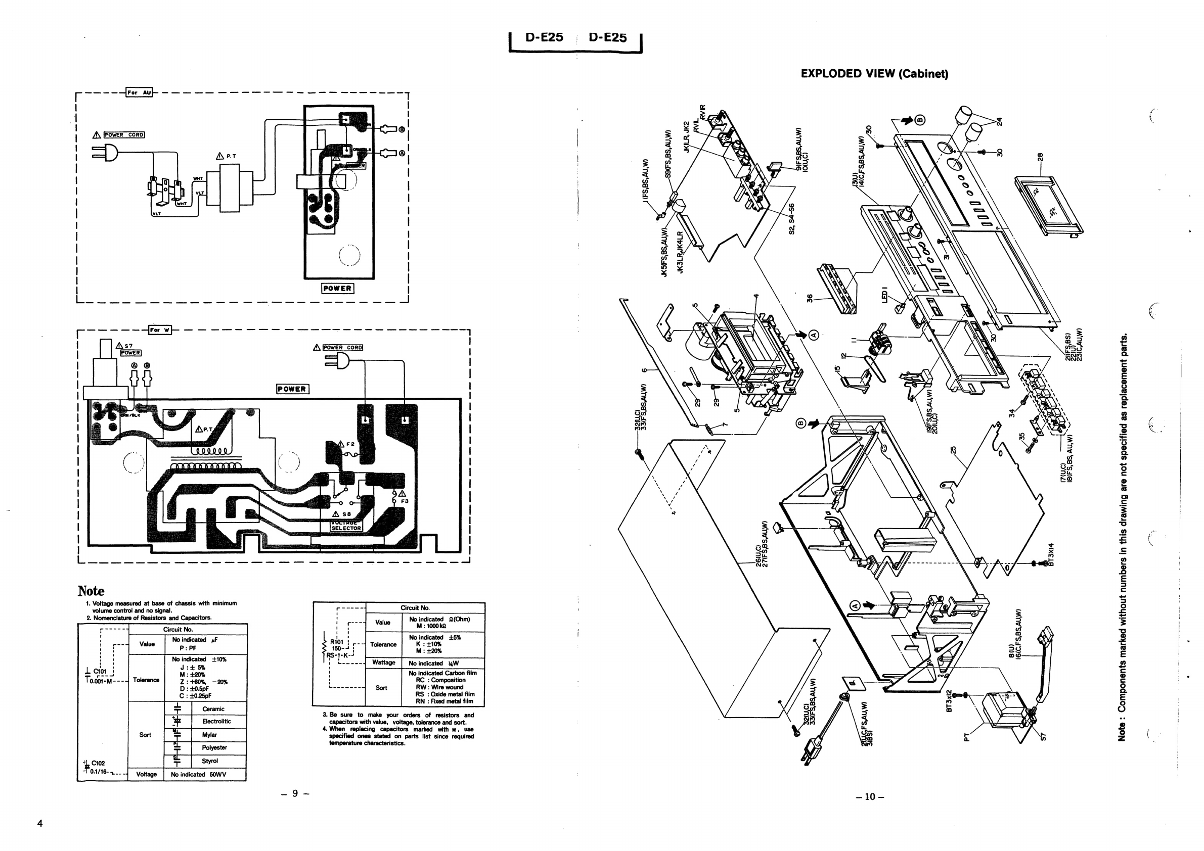
Exploded
view
(Cabinet)................::csccessssseneceeeeeees
10
Replacement
parts
list
............
cscs
eeceeeeenecesseeens
11
OMOHOD
@
OM®Q
OM
©
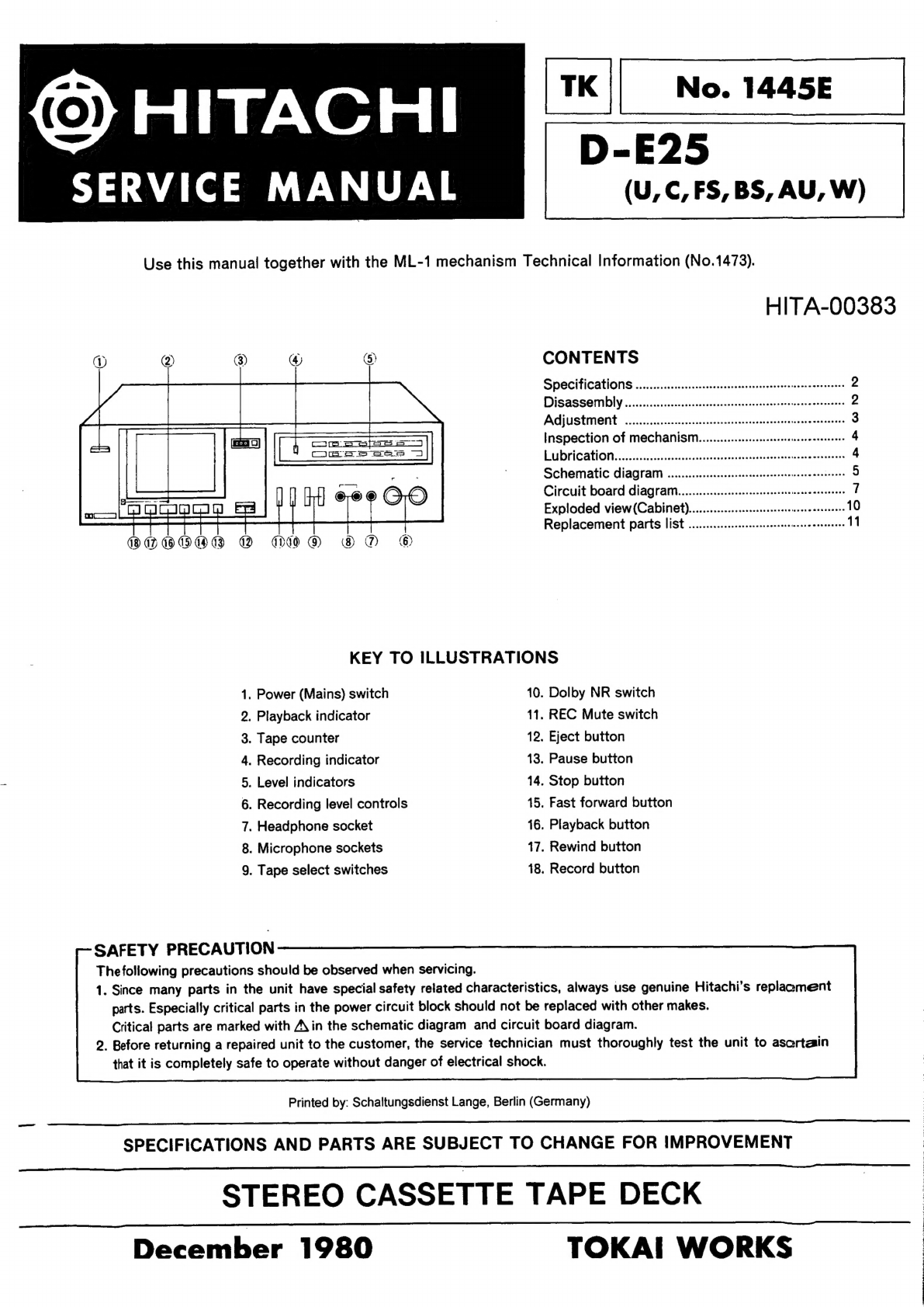
KEY
TO
ILLUSTRATIONS
1.
Power
(Mains)
switch
10.
Dolby
NR
switch
2,
Playback
indicator
11.
REC
Mute
switch
3.
Tape
counter
12.
Eject
button
4.
Recording
indicator
13.
Pause
button
5.
Level
indicators
14.
Stop
button
6.
Recording
level
controls
15.
Fast
forward
button
7.
Headphone
socket
16.
Playback
button
8.
Microphone
sockets
17.
Rewind
button
9.
Tape
select
switches
18.
Record
button
SAFETY
PRECAUTION
The
following
precautions
should
be
observed
when
servicing.
1.
Since
many
parts
in
the
unit
have
special
safety
related
characteristics,
always
use
genuine
Hitachi’s
replaemeent
parts.
Especially
critical
parts
in
the
power
circuit
block
should
not
be
replaced
with
other
makes.
Critical
parts
are
marked
with
A\in
the
schematic
diagram
and
circuit
board
diagram.
2.
Before
returning
a
repaired
unit
to
the
customer,
the
service
technician
must
thoroughly
test
the
unit
to
ascertain
that
it
is
completely
safe
to
operate
without
danger
of
electrical
shock.
Printed
by:
Schaltungsdienst
Lange,
Berlin
(Germany)
SPECIFICATIONS
AND
PARTS
ARE
SUBJECT
TO
CHANGE
FOR
IMPROVEMENT
STEREO
CASSETTE
TAPE
DECK
December
1980
TOKAI
WORKS
LE
ae
A
RE
AL
TS,
eT
RTE
EAN
eee
PE
ALE
ae
TEE
RE
EAN
Se
oe
ree
eh
se
Tw
ea
on


 User manual")