HITROL HT-100CT-2 Series User manual

HT(HPC)-100CT-2 Series
HITROL CO., LTD. 1
Doc. no : HT(HPC)100CT2_IM_Eng_Rev.2
Issue date: 2020. 02
HITROL CO., LTD.
HEAD OFFICE.FACTORY.R&D INSTITUDE
HITROL CO.,LTD. 141, Palhakgol-gil, Jori-eup
Paju-si, Gyeonggi-do, Korea
TEL. : (00)-82-31-950-9700
FAX. : (00)-82-31-943-5600
www.hitrol.com
INSTRUCTION MANUAL
CAPACITANCE TYPE LEVEL TRANSMITTER
HT-100CT-2 Series
HPC-100CT-2 Series

HT(HPC)-100CT-2 Series
HITROL CO., LTD. 2
Table of contents
Overview ·······················3
Characteristics ···················3
Operating Principle ··················3
Specifications ······················4
Weather-Proof Version······················4
Ex -Proof Version ·························4
Amplifier Specification ····················5
Product Composition & Technical Data ·····6
Installation ···························8
Metal Tanks ····························10
Non-metal Tanks ························10
Wiring & AMP Composition ··············11
Failure Check & Maintenance ···········18
Product Check ·······················18
Failure Check ·····················18
Precautions for Removal·················18
Precautions for Transportation & Assembly ··19
Precautions for Installation ············19
Precautions for Grounding ·········19
Safety and Environment ············19
Marking ························20
User Training·······················20
Warranty and Contact ···················20

HT(HPC)-100CT-2 Series
HITROL CO., LTD. 3
Overview
Characteristics
Operating
Principle
■Widely used to measure various liquid levels
■Strong structure and semi-permanent life cycle due to moveless part
■Various probe types for wide application
■Easy installation of wire type. (HT-100CTW-2)
■Applicable to corrosive liquid
■Interface measurement between water and oil is available
■Applicable to explosive area (HPC-100CT-2 Series)
■Have KC certificate and CE certificate
HT
(HPC)-100CT-2 Series is a Capacitance Type Level Transmitter which continuously
measures liquid levels using of liquid’s dielectric constant. It can be easily installed and
adjusted, and can be easily applied to corrosive liquids and widely used in general
industries, chemical and oil plants.
When there are two conductors insulated each other, the value of capacitance formed
between two conductors is a function of the sizes of two conductors, relative location of two
conductors and the dielectric constant of material placed between two conductors. Under the
conduction that air of dielectric ε₁ exists in the space between two concentric conductors,
lower part of space between two conductors is filled material of dielectric constant ε₂ as
shown below, the change of capacitance is expressed as follows.
ΔC =
Since is a constant value as an initial condition, and get this value
as K, ΔCbecomes a function of level of material only. Therefore, level can be obtained
through the measurement of ΔC.
log D/d
10
(ε₂ - ε₁ X l
)
[pF]
10
log D/d
(ε₂ - ε₁
)
: Dielectric constant of air
: Dielectric constant of medium (contents)
: Height of tank
: Level of medium (contents)
: Outer diameter of tank
: Outer diameter of sensing probe
ε₁
ε₂
L
I
D
d

HT(HPC)-100CT-2 Series
HITROL CO., LTD. 4
Specifications Weather-Proof Version
Model
HT-100CT-2
HT-100CTH-2
HT-100CTW-2
HT-100CTWH-2
Probe Type
Rod
Wire
Mounting
Screw & Flange
Ambient Temperature
-20°C ~ +60°C
Process Temperature
-40°C~+80℃
-40°C~+150℃
-40°C~+80℃
-40°C~+150℃
Process Pressure
Vacuum~ 20kg/cm2(300#)
Power Source
DC 24V
Output
DC 4~20mA(2~wire)
Enclosure
Weather-Proof (AL Housing IP66)
Wetted Parts Material
SUS 304, 316L with TEFLON
Process Connection
PT 1”(M) Screw
50A JIS 10K RF Flange
Housing ; Cable Entry
PBT;PF1/2”(F),IP65
AL.; PF 1/2''(F), IP66
PBT;PF1/2”(P),IP65
AL.; PF 1/2''(F), IP66
AL;PF1/2”(F),IP66
AL;PF1/2”(F),IP66
Accuracy
±0.5% F.S
Ex-Proof Version
Model
HPC-100CT-2
HPC-100CTH-2
HPC-100CTW-2
HPC-100CTWH-2
Probe Type
Rod
Wire
Mounting
Screw & Flange
Ambient Temperature
-20°C ~ +60°C
Process Temperature
-40°C~+80℃
-40°C~+150℃
-40°C~+80℃
-40°C~+150℃
Process Pressure
Vacuum~ 20kg/cm2(300#)
Power Source
DC 24V
Output
DC 4~20mA(2~wire)
Enclosure
Ex-Proof (Ex d IIC T6, IP65)
Ex-Proof (Ex d IIC T4, IP65)
Ex-Proof (Ex d IIC T6, IP65)
Ex-Proof (Ex d IIC T4, IP65)
Wetted Parts Material
SUS 304, 316L with TEFLON
Process Connection
PT 1”(M) Screw
50A JIS 10K RF Flange
Housing ; Cable Entry
AL. ; PF 3/4”(F)
Accuracy
±0.5% F.S

HT(HPC)-100CT-2 Series
HITROL CO., LTD. 5
Amplifier Specification
Microprocessor
16Bit Microprocessor
Supply Voltage
DC+17V ~ DC+35V @ Typ.+24V
Accuracy
±1% F.S @ With Sensor
Resolution
±1mm
Output Current Range
■3.8mA ~ 20.5mA @ Alarm 3.6mA, 21mA [NAMUR NE43]
■4.0mA ~ 20.0mA @ NAMUR NE43 Holding
Output Current Offset
■Zero : 3.9 ~ 4.1mA
±0.1mA @ 0.01mA Step
■Span : 19.9 ~ 20.1mA
Output Current Definite
TP
Damping Time
■Default 0.5sec
■Range : 0sec ~ 10sec @ 0.5sec Step ADJ.
Accuracy
±0.5% F.S
Self-Diagnosis
■Sensor 미결 시
3.6mA 전류 출력
■Zero 지점보다 낮을 경우
3.6mA 전류 출력
[NAMUR NE43]
■Span 지점보다 높을 경우
21mA 전류 출력
[NAMUR NE43]
Simulation Current Out
■4mA @ 5sec
■12mA @ 5sec
■20mA @ 5sec
State Indicator
■Bi-Color LED [Green]
정상 동작
■Bi-Color LED [Red]
비정상 상태 경고
■Bi-Color LED [Orange]
Zero, Span 미설정
Setting Menu
Quick Menu / Set Menu / UART
Display
mA, %, m, ft, Level, Distance

HT(HPC)-100CT-2 Series
HITROL CO., LTD. 6
Product Composition & Technical Data
The dimensions on the following pages are indicated in mm
Material :
PBT
(Aluminum)
Connection Type
-Screw: PT 1” (Std.), NPT 1”, PF 1”, Others
-Flange: ANSI, JIS, DIN
-Tri-Clamp
Material
-304, 316L, Others
[Housing]
[Connection]
[Probe]
High Temp. Version
High Temp. Version
Material :
Aluminum
Rod Probe
Rod Probe
with Ground rod
Rod Probe
with Ground tube
Wire Probe
Wire Probe
with Ground Wire
Ground
rod
material:
SS w/
Teflon
Ground
tube
material:
SS
Wire
material:
SS w/ Teflon
Weight
material:
SS, Teflon
Weight
material:
SS
Weight
material:
Teflon
Wire Probe
with Ground Wire
(Corrosion)
Probe
material:
SS w/
Teflon

HT(HPC)-100CT-2 Series
HITROL CO., LTD. 7
Dielectric Constant Value
Fuel Oil (Gasoline, Diesel…)
2
Hydrogen chloride
4.6~12
Hexane, Liquid
6
Butanol
17~18
Ammonia
16~25
Alcohol
16~31
Acetone
20
Caustic soda
22~26
Ethanol
25
Methanol
32~33
Glycerin
47~68
Water
81
Sulfuric acid
84
The data of dielectric constant value can be downloaded from technical data by accessing our
website www.hitrol.com.
Rod Probe
Rod Probe w/
Ground rod
Rod Probe w/
Ground tube
Wire Probe
Wire Probe
w/ Ground Wire
Total length (L)
100~3,000
100~3,000
100~3,000
1,000~15,000
1,000~15,000
Probe dia.
(including Teflon)
Ф15
Ф15
Ф15
Ф2.5
Ф2.5
Ground dia.
-
Ф8
(including Teflon)
Ф27.2
-
Ф2.5
(including Teflon)
For acid liquids
O
O
-
O
O
For high-viscosity
liquids
O
O
-
-
-
For non-metal
tanks
-
O
O
O
For sphere tanks
-
O
O
-
O

HT(HPC)-100CT-2 Series
HITROL CO., LTD. 8
Installation
The capacitance type level transmitter can be installed in screw (PT, NPT, PF) and flange
(ANSI, JIS, DIN) as well as tri-clamp and other various locations. Pay attention to the
following matters during installation.
■Product shall be installed at the place far from inlet in order to avoid the malfunction.(a)
■Protection tube shall be applied if there is a flow or slopping of the medium of the tank. (b)
■Probe shall be installed within Max. 300mm from the tank wall and ground tube type
shall be applied if the distance between the tank wall and sensing probe is far or the tank
material is non-conductive. (c)
■Ground rod type shall be used for corrosive liquid. (d)
■Bracket insulated to a sensing probe shall be installed at the bottom of probe in order to
fix it if the probe length is long or there is slopping of medium in the tank. (e)

HT(HPC)-100CT-2 Series
HITROL CO., LTD. 9
■Ground tube or ground rod type shall be applied for concrete or non-conductive tank as
per above figure. (g)
■Ground tube type shall be applied for ball tank and external chamber shall be installed for
side mounting of tank. (h)
■When side mounting, the chamber shall be installed. (i)
■Ground tube에는 적절한 위치에 vent holes이있어야 합니다.(j)
(g)
(j) Vent holes
(i)
(h)
(j) Vent holes

HT(HPC)-100CT-2 Series
HITROL CO., LTD. 10
■Metal Tanks (Conductive tank)
When installing on a conductive tank, the transmitter housing and tank shall be grounded as
shown below.
되어야 합니다.
■Non-metal tanks (Non-conductive tank)
When installed on a non-conductive tank, use the ground tube (rod) or ground wire type.
Also, the transmitter housing and tank shall be grounded as shown below.

HT(HPC)-100CT-2 Series
HITROL CO., LTD. 11
Wiring & AMP Composition
■Set Menu Function
No.
Contents
Description
Remarks
[00]
mA / % Unit Set
: mA : percent (※[02], [03] setting unit)
[01]
Level / Distance Set
: Level : Distance
Quick Menu
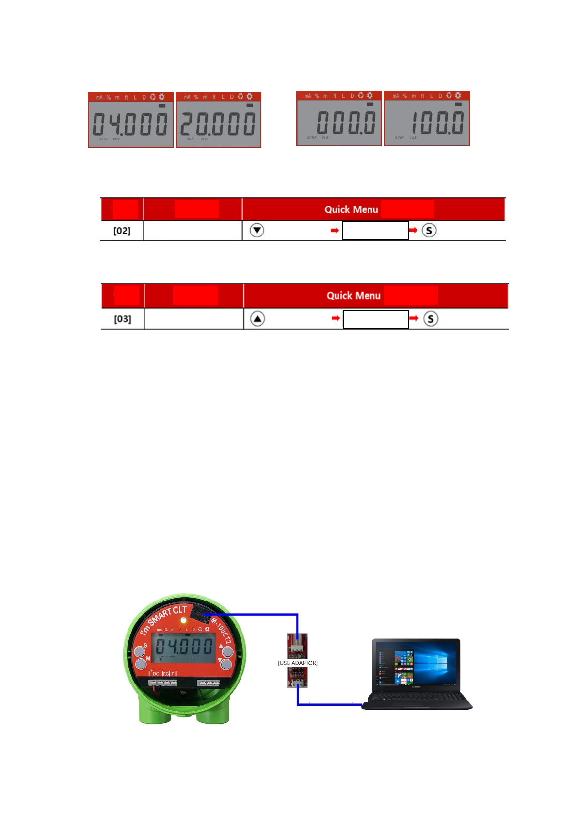
[02]
Zero Point Set
0.0 ~ 95.0% or 4.000 ~ 19.200 mA setting
Quick Menu
[03]
Span Point Set
5.0 ~ 100.0% or 4.800 ~ 20.000 mA setting
Quick Menu
[04]
Zero Height Set
Level setting criteria
※-9.999~99.999m (User setting)
[05]
Span Height Set
[06]
Tank Height Set
[07]
NAMUR NE43 Set
NAMUR NE43 function setting and holding
[10]
Damping Time Set
0 ~ 10 sec. (Default 0.5 sec @ 0.5 sec Step ADJ.)
[20]
Zero Output Current Adjustment
-0.100~ 0.100 mA (0.001mA Step ADJ.)
※When the output current is adjusted offset
[21]
Span Output Current Adjustment
[30]
Rotation Time
0.5 ~ 10 sec. (Default 1 sec @ 0.5 sec Step ADJ.)
[31]
'mA' Display On/Off
Rotation ‘mA’select display
[32]
'%' Display On/Off
Rotation ‘%’select display
[33]
'Meter' Display On/Off
Rotation ‘Meter’select display
[34]
'Feet' Display On/Off
Rotation ‘Feet’select display
[40]
4mA Output
Output “4mA”for 5 sec
Quick Menu
12mA Output
Output “12mA”for 5 sec
20mA Output
Output “20mA”for 5 sec
[90]
Error Number Output
Display of error number according to malfunction
[91]
Capacity value Output
Display Zero, Span, and current measured value
[100]
Reset
Reset the all setting
[Table 1] Setting Menu List
■Module Composition
- Make sure to connect the power with correct polarity (+, -), and the power supply shall be between +17V ~ 40V.
- Do not connect the wire with the power connected.
1. S : Function setting / Save the setting
2. M : Mode Change / Cancellation
3. ▲: Span Set / Setting the value left / up
4. ▼: Zero Set / Setting the value right / down
5. LCD : Display of operating and setting status
6. LED : Display of power and status
7. UART : Communication port of HT-100CT-2 setup and operation status
8. PWR : For supply power and current output / check for output current
9. N/A : Not used

HT(HPC)-100CT-2 Series
HITROL CO., LTD. 12
■Operating method
The cursor moves sequentially whenever the button is pressed.
The order of movement is as follows.
mA % m ft mA % …
□Into the Setting Menu
In the Setting Mode, press button for 1 second then the green LED will be flickering and you can go
into the Setting Menu.
□Return to the Setting Mode
In the Setting Menu, press button for 1 second then the green LED will be flickering and you can go
back to the Setting Mode.
□Select the Setting Menu
In the Setting Menu, use / buttons to select the user setting function.
Pressing button for 1 second will enter the function.
About 1 sec.
/ About 1 sec.
About 1 sec.
Display mode
Cursor
Segment
Bar graph
(User setting)
(User setting)

HT(HPC)-100CT-2 Series
HITROL CO., LTD. 13
□Change the User Setting
If just 1 digit is flickering, it can be moved between the digits.
If full digits are flickering, it can only be set up to the specified number.
□User Key Button
■Height Setting
Key Button
Function
Press more than 1 sec.
Increasing of digits(Left)
Press more than 1 sec.
Decreasing of digits(Right)
Press shortly
Increasing of the numerical value
Press shortly
Decreasing of the numerical value
Press more than 1 sec.
Save and Leave
Press more than 1 sec.
Leave without Save
Change of digits
and value
Level
This refers to the direction in which the medium is raised based on the
bottom of the tank.
Zero Height
The distance from the bottom of the tank to the zero point is called
“Zero Height”.
Span Height
The distance from the bottom of the tank to the span point is called
“Span Height”.
Tank Height
The distance from the bottom of the tank to the top of the tank is
called “Tank Height
Distance
This refers to the direction of the downing of the medium from the
top of the tank.
[Table 2] Key Button Guidance
HT(HPC)-100CT-2 Series
HITROL CO., LTD. 14
□Zero, Span Quick Setting
■Zero Setting
■Span Setting
■Others
▶Zero & Span can be set regardless of display mode status
▶It can set, save, and cancel the values. (Refer to Table 2)
▶The level shall not be changed when Zero & Span are setting.
mA Setting
Percent Setting
■UART Monitoring
You can only check the state of the adjusted setting values using your PC or Smartphone, and
the execution method is the same. (Password: 1975)
Run screen configuration: You can check the sensor measurement status, sensitivity setting
value, relay setting status, etc.
■Monitoring using a PC
Component –PC, USB Extension cable (typical USB to Micro USB B), UART ADAPTOR
Zero Setting
Span Setting
Press for 1 sec.
Press for 1 sec.
Press for 1 sec.
Press for 1 sec.
Input the value
Input the value
[USB Extension cable]
[HT-100CT-2 PC UART Compositions]
No.
No.
Contents
Contents
Setting
Setting

HT(HPC)-100CT-2 Series
HITROL CO., LTD. 15
[HT-100CT-2 PC UART Launch Screen Compositions]

HT(HPC)-100CT-2 Series
HITROL CO., LTD. 16
Output
Input
[A Description of the Current Operating Status (##Err State)]
[HT-100CT-2 PC UART Launch Screen Compositions Function]
Unit Set
Set
Set
Set
Height Set (Based on level)
Height Set (Based on level)
Height Set (Based on level)
Function Set
Set
Adjustment
Adjustment
Adjustment
Select
Reset
Capacity Value of Current Measured
Capacity Value of Span Setting
Capacity Value of Zero Setting
Current Output of Current Value (01.BasedonOutputSelectSetting)
Current Output of Percentage Value (01.BasedonOutputSelectSetting)
Current Output of Length Value (01.BasedonOutputSelectSetting)
Current Output of Feet Value (01.BasedonOutputSelectSetting)
Current Operating State
Normal operation
Problem for sensing
Below or above thesetvalue of Zero or Span
Abnormal setting
Sensor cable open circuit, short, broken probe insulation, module sensor failure, etc
NAMUR ME43 Caution area (below 4mA, above 20mA)
Zero, Span conversely set state
No.
Contents
Description
Remarks

HT(HPC)-100CT-2 Series
HITROL CO., LTD. 17
■Monitoring using a Smartphone
Component –Smartphone (Android OS), OTG, USB Extension cable (typical USB to Micro USB B), UART
ADAPTOR
Application –Refer to “Serial USB Terminal Install & Setting Guide”
[USB Extension cable]
[HT-100CT-2 Smartphone UART Compositions]
[HT-100CT-2 Smartphone UART Launcher]
[HT-100CT-2 Smartphone UART Exit]
[Open App]
[Home screen]
[Select the UART Connection]
[Enter the password]
[Operation screen]
[Enter exit command]
[End of program]
[Select the UART Disconnection]
[Enter exit and Fly command]
[Enter PW and Fly command]
Continue

HT(HPC)-100CT-2 Series
HITROL CO., LTD. 18
Failure Check
& Maintenance
Precautions
For Removal
■Check the level and presence of medium in the tank before removing it.
■Wear gloves when removing it, to prevent a burn.
■If there is explosive gas atmosphere, do not open the cover.
■Disassemble work shall be done with the power off.
■Make sure than any O-ring or gasket is not damaged while opening or closing the cover of product.
■Product Check
The major parts of the HT
(HPC)-100CT-2 Series level transmitters to be inspected are
divided into the sensor element and the transmission element. The life spans of major
parts vary with user environments and can be used in optimum conditions through
periodic inspections. Therefore, the user shall maintain and repair the product through
periodic inspections conducted at least once a year. In addition, check for the exterior of
the product like visual damage. If the medium or foreign substance is attached to the
probe, it will cause bad accuracy, so it shall be removed regularly. Be careful not to
damage the Teflon part during removal.
■Failure Check
The level of measured object changes, but the output does not change.
▶Insufficient power supply
▶Wrong adjustment of ZERO and SPAN
Only a slight change of output to the change of level of medium is present.
▶Wrong adjustment of ZERO and SPAN
▶A slight change of probe ΔC value
No change of level, but output fluctuation is present.
▶Wrong grounding
▶Noise on the lines
▶Extreme fluctuation of medium
▶Bad insulation of probe
Output indicates full (20mA) of higher regardless of the change of level of the medium.
▶Wrong adjustment of ZERO and SPAN

HT(HPC)-100CT-2 Series
HITROL CO., LTD. 19
Precautions
for
Transportation
& Assembly
Precautions
for
Installation
Precautions
for
Grounding
(Ex-proof)
Safety and
Environment
■Precautions for Use
- Make sure to connect the product and vessel using required tools for sure.
- Keep the lock key safe and make sure that it is locked.
- Do not apply high impact to the product.
■Precautions for Wiring
- Make sure to wire contacts correctly. (Refer to Wiring)
- Wire and supply the power to the device after checking the specifications.
- Pay attention to prevent electric shock.
■Disposal of Product
- Make sure to separate the amplifier and main unit from housing before disposing the
products. Also, the amplifier shall be detached and discard the metal and non-metallic
materials. No part (ex. Mercury switch) has influence on the environment, so no special
attention is required.
■Pay special attention to prevent any impact on the device during transportation or assembly.
■Pay attention to prevent any damage to any packing when transporting or mounting
the machine to the vessel.
■Use the same standard flange or screw.
■Make sure to insert washers between bolts and nuts to prevent loosening.
■Make sure to insert gaskets between flanges.
(Select the gaskets in consideration of temperature of content and pressure of vessel.)
■Install an Ex-proof product only in an Ex-proof zone.
■After the installation is complete and the cover of the product is assembled, power it on.
Please do not apply high impact to the product.
■When connecting to an external ground, the ground wire shall be 4㎟(4mmSQ).
Make sure to insert a washer if the terminal lug is removed from ground terminal and
then re-connected. (Loosening prevention)
HEAD (Weather-proof)
HEAD (Ex-proof)
External ground 4㎟
(4mmSQ)

HT(HPC)-100CT-2 Series
HITROL CO., LTD. 20
Marking
User
Training
Warranty
and Contact
■Warranty and Service
This product is subject to the warranty for 2 years of shipments and unpaid service
will be provided for any damage found under normal operating conditions. If it is
not about the failure of product, the service charge will be payable.
You can request A/S at our website or by contacting our headquarters.
■Headquarters ․Factory ․Laboratory Contact Number
Address: HITROL CO., LTD 141, Palhakgol-gil, Jori-eup, Paju-si, Gyeonggi-do, Korea
TEL: 031-950-9700 (Headquarters & A/S)
FAX: 031-950-9796 ~ 9799 (Headquarters & A/S)
■Product Identification
- The product identification mark is attached onto the housing and shows the model
name, serial number, working temperature, working pressure, and matters regarding
output. The serial number is a unique manufacturing number for the identification of
products.
The fluid temperature of the container shall be up to 80℃for Weather-proof type. For
high temperature, the fluid temperature shall not exceed 150℃. In addition, make sure
that the ambient temperature of housing is kept at -20℃~ +60℃.
An Ex-proof product is pressure-resistant and Ex-proof type, so never open the cover
during operation.
Do not apply the Non Ex-proof product in an Ex-proof zone.
Ex-proof
Weather-proof
Other manuals for HT-100CT-2 Series
1
This manual suits for next models
9
Table of contents
Other HITROL Transmitter manuals

HITROL
HITROL HT-100R Series User manual

HITROL
HITROL HT-100R Series Configuration guide

HITROL
HITROL HT-100F Series User manual

HITROL
HITROL HT-100R Series User manual

HITROL
HITROL HT-100CT-2 Series User manual

HITROL
HITROL HTMF-MF User manual

HITROL
HITROL HT-100PT User manual

HITROL
HITROL HT-100CT Series User manual

HITROL
HITROL HT-100F Series User manual

HITROL
HITROL HT-100F Series User manual


