HITWAY BK7 User manual

BK7 Quick Installation Guide


EN------------------------------------------------------01
DE------------------------------------------------------15
FR------------------------------------------------------29
ES------------------------------------------------------43
IT-------------------------------------------------------57
NL------------------------------------------------------71
PL------------------------------------------------------85

Install the Handlebar..............................................2
Install the Front Fender..........................................4
Install the Front Wheel...........................................6
Install the Rear Fender...........................................8
Install the Pedals....................................................8
Install the Saddle....................................................10
Install the Front Reflector........................................11
Install the Wheel Reflectors....................................11
Switch on and off Operation...................................12
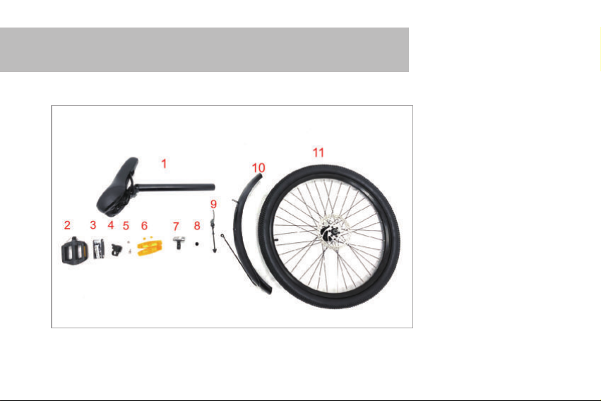
Parts Introduction
BK7 Parts
1. Saddle and Seatpost
2. Pedals
3. 16-in-1 Multi-function
Tool
4. Bell
5. Headlight Fixing Screws
6. Wheel Reflectors
7. Front Reflector
8. Top Cover Screw Plug
9. Front Wheel Quick
Release Lever
10. Front Fender
11. Front Wheel Set
-1-

1. Install the Handlebar
1. Rotate the handlebar tube towards the front of the bike and adjust
the tube and fork to be parallel and perpendicular to the frame.
1
2. Use the No. 5 Allen key from
the 16-in-1 tool to tighten the
top cap screw.
3. Use the No. 4 Allen key in the 16-in-1 tool to
tighten the screws "a" and "b" in the picture.
Note: The two screws should be tightened
gradually, do not tighten one first, then tighten the
other one.
2
3
-2-
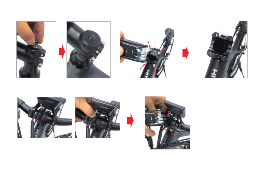
4. Fasten the top cover screw plug. 5. Remove the 4 front cover screws with the No. 4 Allen key
in the 16-in-1 tool and remove the tube front cover.
6. Place the handlebar into the tube and center the
handlebar angle.Then close the front cover.
NOTE: Do not twist the wire harness.
7. Use the No. 4
Allen key in the
16-in-1 tool to
gradually tighten the
4 front cover screws
in the order shown
in the picture.
45
67
-3-

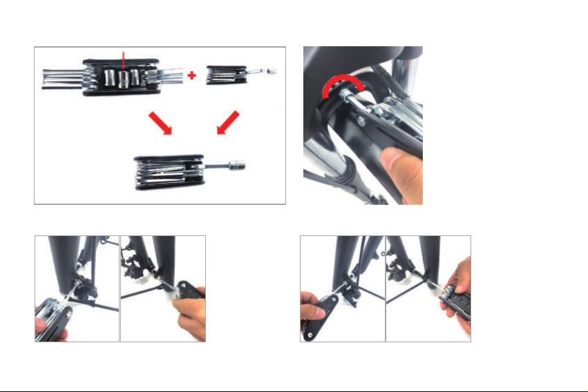
2. Install the Front Fender
1 2 3
1. Pre-install the headlight and
the fender on the front fork with
the headlight fixing screws.
2. Tighten the screw
with the No. 5 Allen
key in the 16-in-1 tool.
3. Pre-tighten the nut.
-4-
4 5
6 7
4. Take out the
10mm sleeve and
combine the
16-in-1 tool as
shown in the
picture.
5. Tighten the nut
with the combined
tool.
6. Use the No.
4 Allen key in
the 16-in-1 tool
to remove the
fender support
screws
pre-installed on
the left and
right sides of
the front fork.
7. Fix the front
fender support
rods to the
corresponding
screw holes of
the front fork
and use the No.
4 Allen key in
the 16-in-1 tool
to tighten the
screw.
-5-
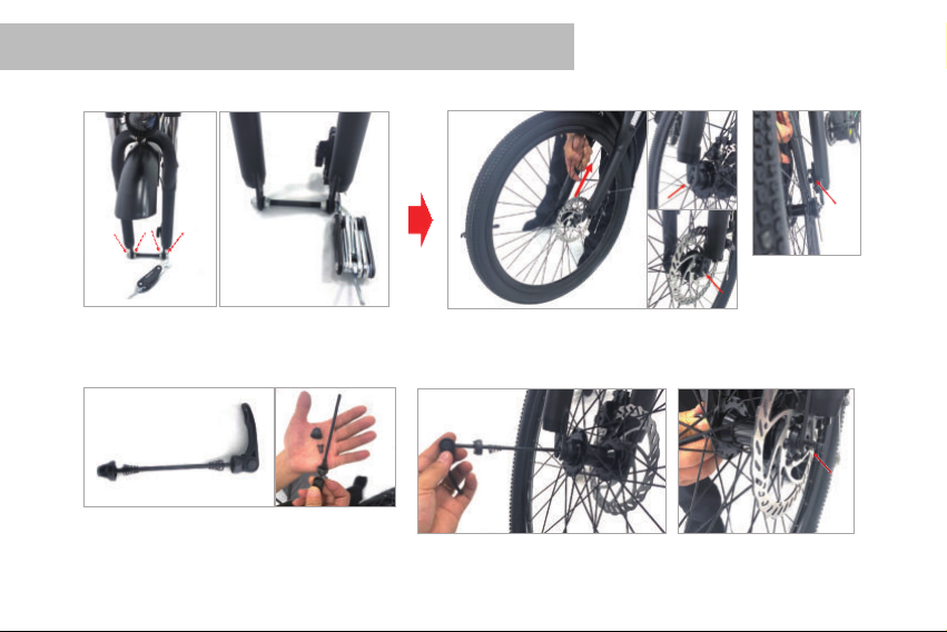
3. Install the Front Wheel
1
34 5
2
1. Unscrew the nut in the picture with the No.
15 open-end wrench in the 16-in-1 tool, and
remove the support shaft.
2. Put the front wheel into the front
fork hook and snap it.
NOTE: Put the disc
brake pads into the
disc brake.
3. Unscrew the quick release rod nut
and take out a conical spring. 4. Insert the quick release lever. 5. Install the conical
spring as shown.
-6-

5
6
5. Screw on the quick release rod nut as shown.
6. Adjust the direction of the handle, adjust
the screw to a suitable tightness, and fasten
the handle upward.
Note: During this process, ensure that the
front wheel is in the center of the front fork
tube. If there is any deviation, please loosen
the handle to adjust the position of the front
wheel, and then lock the handle.
-7-

5. Install the Pedals
4. Install the Rear Fender
1 2
1. Use the No. 4 Allen wrench in the 16-in-1 tool to
remove the fixing screws of the mud plate support rods
pre-installed on the left and right sides of the frame.
2. Fix the rear fender support rods to the
corresponding screw holes of the frame
and use the No. 4 Allen key in the 16-in-1
tool to tighten the screws.
The "R" marked on the pedal shaft means the right
pedal, and the "L" mark means the left pedal.
-8-

Right Pedal Installation Method:
The “R” marked on the pedal shaft means the right pedal. First, rotate the pedal shaft clockwise
to pre-screw it into the right crank with a chainring, and then use a No. 15 open-end wrench
clockwise to tighten it.
Left Pedal Installation Method:
The "L" marked on the pedal shaft means the
left pedal. First, turn the pedal shaft counter-
clockwise by hand to pre-screw it into the left
crank, and then use a No. 15 open-end
wrench to turn it counterclockwise to tighten it.
-9-

6. Install the Saddle
Pull adjustment handle of the seatpost in the
direction shown in the picture.
Insert the seatpost and adjust it to the desired
height
(Note: the length of seatpost inserted should
exceed the safety mark).
Press the handle in the direction shown in
the figure.
Note: If the handle is too tight or too loose,
please adjust the screw at "1" in the figure
appropriately.
1
-10-

7. Install the Front Reflector
8. Install the Wheel Reflectors
Snap the wheel
reflector into the
spoke .
(Note: the spoke
should be inserted
into the slot in the
middle of the wheel
reflector) Turn in the reflector buckle, and screw it about 90
degrees with the flat-blade screwdriver in the
16-in-1 tool to fix the tightening wheel reflector.
Using the Phillips
screwdriver in the 16-in-1
tool, loosen the screws
on the front reflector
bracket.
Put the front
reflector bracket into
the corresponding
position of the
handlebar, and
tighten the screw
with the Phillips
screwdriver in the
16-in-1 tool.
-11-
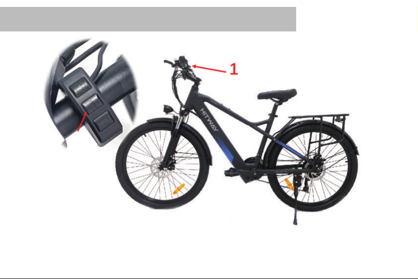
9. Switch on and off Operation
Long press the "i" button at “1”in the picture to turn the bike on or off.
-12-

-13-
Thank you for choosing us HITWAY. We provide warranty
and lifetime after-sales support for our HITWAY products.
If you have any questions, please contact our after-sales
support team. We will provide you with technical support
and suitable solutions as soon as possible.
Email: support@hit-way.com
MAINTENANCE CONTACT INFORMATION:QR code:

Einbau des Lenkers..............................................16
Installation des vorderen Schutzblechs.................18
Einbau des Vorderrads..........................................20
Installation des hinteren Schutzblechs...................22
Installation des Fußpedals.....................................22
Installation des Sitzpakets.....................................24
Installation des vorderen Reflektors......................25
Installation des Radreflektors................................25
Ein/aus schalten....................................................26

Teilebeschreibung
BK7 Teile
1.Sitzpaket Sitzrohr
2.Pedale
3.16 in 1 Werkzeug
4.Glocke
5.Scheinwerfer-Befesti-
gungsschrauben
6. Radreflektoren
7. Frontreflektor
8. Standrohr-Verschlusss-
chraube
9. Vorderrad-Schnellspann-
hebel
10. vorne Schutzblech
11. Vorderrad
-15-

1. Einbau des Lenkers
1. Drehen Sie das Lenkerrohr zur Vorderseite des Fahrrads und stellen
Sie das Rohr und die Gabel so ein, dass sie parallel und senkrecht zum
Rahmen stehen.
1
2.Ziehen Sie die Schrauben
mit dem Inbusschlüssel Nr. 5
im 16-in-1-Werkzeug fest.
3. Verwenden Sie den Inbusschlüssel Nr. 4 im
16-in-1-Werkzeug, um die Schrauben „a“ und „b“ in der
Abbildung festzuziehen.
Hinweis: Die beiden Schrauben sollten nach und nach
angezogen werden, ziehen Sie nicht zuerst eine fest,
dann ziehen Sie die andere fest.
2
3
-16-
Table of contents
Languages:
Other HITWAY Bicycle manuals


