HITWAY BK8 User guide
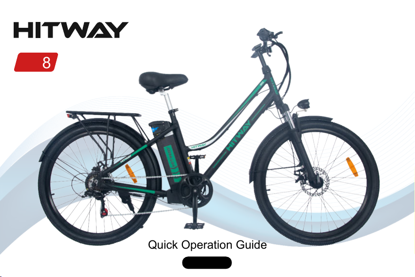
BK8
Quick Operation Guide
V2022.0.2


EN------------------------------------------------------01
FR------------------------------------------------------16
DE------------------------------------------------------31
ES------------------------------------------------------46
IT-------------------------------------------------------61
NL------------------------------------------------------76
PL------------------------------------------------------91

1. Install the Handlebar Tube
2. Install the Front Fender
3. Install the Front Wheel
4. Install the Rear Fender
5. Install the Pedals
6. Install the Seat Tube
7. Install the Front Reflector
8. Install the Wheel Reflector
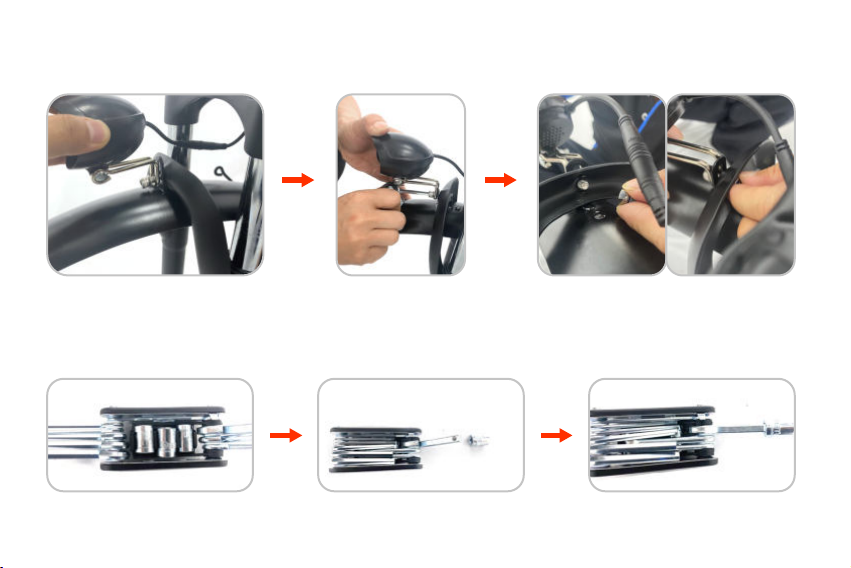
9. Install the Bell
10. Power-on Show
-1-
Parts introduction
BK8 Parts
1
2 3 4 5 6 7 8
9
10
11 12
1. Seats and seatposts
2. Pedals
3. 16 in 1 Tool
4. Bell
5. Headlight fixing screw
6. Wheel reflectors
7. Front reflector
8. Tube Screw plug
9. Headset dust cap
10. Front wheel quick release lever
11. Front fender
12. Front wheel set
-2-
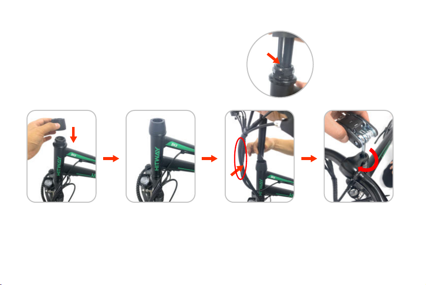
1. Install the Handlebar Tube
1 2 3
Note: The inserted
part should exceed
the safety mark.
1. Put the headset dust cap on the frame
head tube.
2. Insert the handlebar
tube into the frame head
tube.
NOTE: Do not twist the
wire harness.
3. Pre-tighten the screws
with the No. 6 Allen key
from the 16-in-1 tool.
(don't lock too tight)

-3-
4
4. Adjust the relative parallelism
between the handlebar, front fork
and frame.
7. Rotate clockwise or
counterclockwise to
adjust the handlebar to
a suitable angle.
8. Use the No. 6 Allen
key in the 16-in-1 tool
to tighten the screws to
lock the handlebars.
5. Tighten the screws with
the No. 6 Allen key in the
16-in-1 tool.
6. Fasten the tube
screw plug.
5
7 8
6
-4-
2. Install the Front Fender
1. Pre-install the headlights and
fenders on the front fork with the
headlight fixing screws.
Take out the 10mm sleeve. 4. Assemble the 16-in-1 tool as shown.
2. Tighten the screw with
the No. 5 Allen key in the
16-in-1 tool.
3. Pre-tighten the nut.
1
4
2 3
-5-
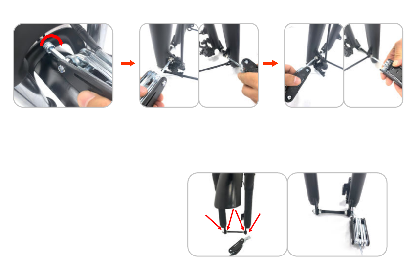
3. Install the Front Wheel
5. Use the assembled tool
to tighten the nut.
6. Use the No. 4 Allen key in the
16-in-1 tool to remove the fixing
screws of the mud plate support
rods pre-installed on the left
and right sides of the front fork.
1. Loosen the nut shown in the
picture with the No. 15 open-end
wrench in the 16-in-1 tool and
remove the support shaft.
7. Fix the front fender support to
the corresponding screw holes
of the front fork and use the No.
4 Allen key in the 16-in-1 tool to
tighten the screws.
5 6 7
1

-6-
2. Put the silver disc brake into the brake system. Put the silver disc brake
into the brake system.
2

-7-
3. Unscrew the quick release rod
nut and take out a conical spring.
4. Insert the quick release lever. 5. Install the conical spring as shown.
3
4 5
Other manuals for BK8
1
Table of contents
Languages:
Other HITWAY Bicycle manuals


