HOLT HI?1590 User manual

AN‐1590,Rev.NewHOLTINTEGRATEDCIRCUITS10/10/14
23351 Madero,
Mission Viejo, CA
92691. USA.
Tel: + 1 949 859 8800
Fax: + 1 949 859 9643
Web: www.holtic.com
HI‐15901553BDualTransceiver
WithSPIAmplitudeControl
EvaluationBoard
UserGuide
October,2014

AN‐1590,Rev.NewHOLTINTEGRATEDCIRCUITS10/10/14
INTRODUCTION
TheHoltHI‐1590EvaluationBoarddemonstratesfeaturesoftheHI‐1590MIL‐STD‐1553Bdual
transceiverIC.ThisdevicetransmitsandreceivesManchesterencoded20bitMIL‐STD‐1553B
serialdatasuitablebustransformers.Transceiverdriveamplitudecanbedigitallyadjustedfrom
0to26Vp‐pthroughtheSPIinterface.Adjustmentcanalsobemadewitha0to3.3VDCanalog
controlsignal;apotentiometerisprovidedforthis.Amplitudecontrolsforbothbusesare
gangedtogether.InSPImode,alowrangeoptionallowsformoreaccurateamplitude
adjustmentfrom0to4.9Vp‐p.Theboardrunsfromasingle3.3V±5%supplyvoltage.AMIL‐
STD‐1553Bprotocolmessagegeneratorandreceiverareincludedontheboardtodemonstrate
theHI‐1590features.TheEVM(EvaluationModule)includesamicrocontrollerthatgenerates
theSPImessages,theinterfaceisthroughaterminalemulatorconnectedtoaPCthroughthe
USBinterface.TheEVMisshowninthepicturebelow:
Fig1–HI‐1590EvaluationBoard

AN‐1590,Rev.NewHOLTINTEGRATEDCIRCUITS10/10/14
Thisguidesummarizeshowtosetupandrunningquickly.
KITCONTENTS
ThisUserGuide
HI‐1590EvaluationBoard
MiniUSBSerialCable.
BoardBlockDiagram
MC9S12XD
16 Bit MCU USB
DIP SW
(4) DIP SW(6)
RESET Button
3.3V
Supply
RESET Transceiver A DB2791
TRANSFORMER
HI-1590
BUSA
Transceiver B DB2791
TRANSFORMER BUSB
Message A
1553B
Message
Generator
Message B
RUN
EEPROM
1EEPROM
2
BC RT DIP SW
(5)
ANALOG CONTROL
VCONT
ACTIVE

AN‐1590,Rev.NewHOLTINTEGRATEDCIRCUITS10/10/14
LEDFunctions
REFNAMEDEFAULT DESCRIPTION
LED1POWERONIndicatedwhen3.3Vpowerispresent
LED2ACTIVEOFFFlashesatthestartofa1553messagetransmitsequence
LinkJumperFunctions
REFNAMEDEFAULT DESCRIPTION
J4LINKFORPOTOFFLinktousepotentiometerR3toadjustoutputamplitude
J5LINKFORSPIONLinktouseSPItoadjustoutputamplitude
J8HOLDINRESETOFFHoldsthemicrocontrollerinreset,forinstancewhileusingan
externalSPIinterface.
J12BC/RTBCConnectsmemoryforBCorRTmessages
WiredJumperFunctions(JP)
REFNAMEDEFAULT DESCRIPTION
JP1ONLinktouseon‐board70ΩloadonBusBoutput
JP8ONLinktouseon‐board70ΩloadonBusAoutput
JP2,3,4,5JP4,5ONOptionlinksfortransformervariants,BusB
JP6,7,9,10JP6,9ONOptionlinksfortransformervariants,BusA
JP11ONConnectsBusAnegativeoutputtoground
JP12ONConnectsBusBnegativeoutputtoground
JP13‐16ONCutifusinganexternal1553messagegenerator

AN‐1590,Rev.NewHOLTINTEGRATEDCIRCUITS10/10/14
SwitchFunctions
REFNAMEDEFAULT DESCRIPTION
SW1/1
VSELONSelectsoutputcontrolofamplituderange,usingSPI.
ON=SPIcontrol0‐24V,Low=SPI,0‐2.4V
SW1/2TXAINHOFFInhibitsthetransmitteroutputoftransceiverA
SW1/3TXBINHOFFInhibitsthetransmitteroutputoftransceiverB
SW1/4RXAENONEnablesthereceiveroftransceiverA
SW1/5RXBENONEnablesthereceiveroftransceiverB
SW3RUNPress=Starts1553messages
SW4STOPPress=Stops1553messages
SW5/1‐5AUTOENetc01101Messageloadingcontrol(leaveindefault)
SW6/1‐6RT1A4:0,RT1AP000000RTAddress(onlyusedifRTmodeavailable)
SW7RESETPresstoresetthemicrocontrollerandcontrolsoftware
ConnectorFunctions
REFNAMEDESCRIPTION
J1BUSB1553BusAconnection(secondaryoftransformer)
J2BUSA1553BusBconnection(secondaryoftransformer)
J3/1,2RXA/nRXADifferentialLogicsignalfromHI‐1590BusAreceivedatapins
J3/3,4RXB/nRXBDifferentialLogicsignalfromHI‐1590BusBreceivedatapins
J6NotfittedSPIinterfacefortheEEPROMs
J7Dataconnectortoload1553messages
J9USBConnecttoPCtosendSPIcommandsfromterminalemulator
J10ExternalSPIUsetoconnectanexternalSPIforHI‐1590control
J11DebugHeader Usedfordownloadingmicrocontrollerfirmware

AN‐1590,Rev.NewHOLTINTEGRATEDCIRCUITS10/10/14
TestPointFunctions
REFNAMEDESCRIPTION
TP1/TP2BUSB1553BusBconnection(secondaryoftransformer)
TP4/TP6BUSA1553BusAconnection(secondaryoftransformer)
TP3,8,9,10GNDBoardGround
TP5VCONTConnectiontomeasureofinputanalogamplitudecontrol,notethat
J5shouldbeopen.J4shouldbeopenwheninputtingavoltage.
TP6UPDATETestpointforUpdatesignalindicateswhenMIL‐STD‐1553Bwordhas
beenreceived
TP7VSELThispinmonitorsvoltageontheVSELpincontrolontheoutput
amplitude.
High=SPIcontrol0‐24V
Float=AnalogControl
Low=SPIControl,0‐5.1V
TP3,8,9,10GNDBoardGround
TP113V3 VLOGICSupply,connectpowersupplyhere
TP21VDDVLOGICaftersupplyfilter
TP13IRQINTERRUPT
TP14ACTIVEProducespulsejustbefore1553messagestarts,canbeusedto
triggerscope.
TP17/18TXDO/RXDOUSBdata.
TXA,nTXAConnectexternal1553datahereifnotusingtheonboardmessage
generatorforBUSA.NeedtocutlinksTXAandnTXA.
TXB,nTXBConnectexternal1553datahereifnotusingtheonboardmessage
generatorforBUSB.NeedtocutlinksTXBandnTXB.

AN‐1590,Rev.NewHOLTINTEGRATEDCIRCUITS10/10/14
UsingtheBoard
1. Checkallthelinkandswitchpositionscomplywiththetablesabove.Connecta3.3V,1A
supplytothe3V3testpoint.A1Asupplycurrentisrequiredatmaximumamplitude.Verify
the‘PowerOn’LEDislit;theboardshouldtakeabout160mA,whennotsending1553
messages.ConnecttheminiUSBleadtoyourPCandthentotheHI‐1590board.YourPC
shouldautomaticallyinstallthedriver,ifnotthedriverFT231canbeinstalledfromtheHolt
CD.IfyouhaveproblemsinstallingthedriverpleaserefertotheFTDIwebsitebelow:
http://www.ftdichip.com/Documents/InstallGuides.htm
2. AllcontroloftheHI‐1590isdonethroughthe‘ControlConsole’.Thisrequiresuseofa
terminalemulatorforcommunication,suchasHyperTerminalorTeraTerm.TeraTermis
usedwithWindowsversionsofVistaorlaterandissuppliedontheHoltCD.
ToinstallTeraTerm:
UsetheTeraTerminstallerprogramteraterm.exefromtheHoltCD.Acceptthelicense
agreementstatingredistributionispermittedprovidedthatcopyrightnoticeisretained.
ThenoticecanbedisplayedfromtheTeraTermwindowbyclickingHelpthenclicking
AboutTeraTerm.Continuingtoinstall…
AcceptthedefaultinstalldestinationandclickNext.
AttheSelectComponentsscreen,unselectalloptionsexceptAdditionalPlugin=
TTXResizeMenuandclickNext.
Selecttheinstalledlanguage,thenclickNext.
AcceptthedefaultStartMenufolder,thenclickNext.
Selectanydesiredshortcuts,thenclickNext.
AttheReadytoInstallscreen,clickInstall.
RuntheTeraTermprogram.AttheNewConnectionscreen,selectSerialandchoosethe
selectedUSBserialCOMport,youcanfindthecorrectCOMportusingDeviceManager.
3. ClickSetupthenSerialPorttoopentheserialportsetupwindow.
ChoosetheCOMportforthemini‐USBconnectionandthenselectthefollowingsettings:
BaudRate:115200,Data:8bits,Parity:none,Stop:1bit,FlowControl:none
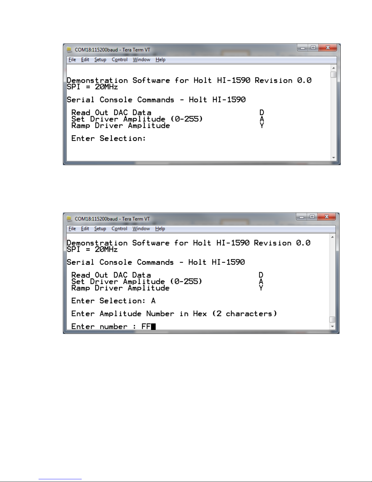
4. Theevaluationsoftwareispreprogrammedintothemicrocontrollerandwasloadedatthe
HoltApplicationsSupportCenter.Onpressingthe‘RESETMICRO’buttonontheboard,the
softwaredisplaysamessageonthemonitor,asshownbelow.

AN‐1590,Rev.NewHOLTINTEGRATEDCIRCUITS10/10/14
Note:Ifunderanycircumstancesthesoftwarelocksup,usethe‘RESET’keytorestart.
5. Pressthe‘A’keytosettheoutputamplitude.Enterthemaximumamplitudeof‘FF’asshown
below.
6. ConnectanoscilloscopetotheABUSandBBUSterminal,withthegroundsgoingtonABUS
andnBBUSrespectively.Groundingthenegativebusterminalsprovidesdifferentialvoltage
measurementsusingjustonescopeprobeperbus.TriggerthescopefromtheACTIVEtest
point.PresstheSTOPbutton,thisloadsthe1553messages.PresstheRUNbuttontostart
messagetransmission.ThemessageswillbetransmittedalternatelyontheAandBbuses.
Checkthata1553signalofabout24Vp‐pamplitudeisseenononeofthebuses,asshownin
Fig2below.Every5secondsitwillswitchtotheotherbusandduringtransmissionyou
shouldseethe3.3Vsupplycurrentgouptoabout1A.

AN‐1590,Rev.NewHOLTINTEGRATEDCIRCUITS10/10/14
Fig2:YellowisBUSAoutput,greenisBUSB,RedistheACTIVEtriggersignal
7. TheHI‐1590canalsoreadbackdatafromtheDACregisterbutonlyafteravaluehasbeen
writtenintotheregister.Pressthe‘D’key,typein‘80’,theprevioussettingof‘FF’shouldbe
readoutasshownbelow.Observetheamplitudeonthescope;thisshouldbereducedby
half,orapproximately12Vp‐p.
8. TheSPIsoftwarehasarampfunction,thisrampstheamplitudeonbothoutputsupto
maximumandbackdowntozeroina‘sawtooth’function.Pressthe‘Y’buttonandobserve
theamplituderisingandfalling.WhilstinthismodeswitchtheVSELswitchto‘Low’,this
selectsthelowamplitude,youshouldseetheoscilloscopetracegodowntoonefifth
maximumamplitudeorabout5V.
9. AswellasSPIcontrolofamplitudethroughaDAC,theHI‐1590hastheoptionofusingan
analogvoltageof0to3.3VDCtocontroltheamplitude.Tousethisfeaturemovethejumper

AN‐1590,Rev.NewHOLTINTEGRATEDCIRCUITS10/10/14
linkfromJ5toJ4.NowamplitudeiscontrolledbypotentiometerR3,turnfullyclockwisefor
maximumamplitude.AnexternalvoltagecanbeusedbyremovingtheJ4jumperand
applyingthevoltagetopin2ofJ4.Therangeis0toVLOGIC(3.3Vnominal)
10. TotestHI‐1590BusAandBusBreceivers,RXENAand/orRXENBswitchesshouldbeinthe
highposition.Any1553BcompliantdataisnowoutputontherelevantRXA/nRXAand
RXB/nRXBpinsofJ3.AnexampleisshowninFig3below:
Fig3:YellowisBUSAoutput,greenisRXAoutput,RedistheACTIVEtriggersignal
11. Ifisolationofthe1553Boutputsisrequiredfromtheboardgroundthesolderedjumpers
JP11andJP12shouldbeopened.

AN‐1590,Rev.NewHOLTINTEGRATEDCIRCUITS10/10/14
In_TXB
BLK
In_nTXB
BUSA
In_TXA
In_nTXA
In_nTXA
RXB
nRXB
KEEP TRACES SHORT AND EQUAL TRACE LENGTH
nRXA
RXA
In_TXA
In_TXB
RXBEN
C5 47uF
C4
4.7uF
In_nTXB
BBUS
B4
B8
JP1 R1
70 1W
JP4
RED
TP1
T1
PM-DB2791S
4
5
6
7
8
1
2
3
nBUSB
BUSB
JP5
BUSB
BLK
LOCATE
C1 AT
PIN 6.
TP2
nBBUS
GND
SCK
nCS
SI
SO
VCONT
R4
0 OHM
1
0
R6
47K R7
47K R8
47K
R9
47K
RXAEN
RXBEN
3V3
3
2145
ON (CLOSED)
SW1
TXIHA
TXIHB
TP7
VSEL
J5 12
R5
1K
VSEL
nBUSA
TXB TXA
nTXAnTXB
TP22
TP24
3V3
C1
100nF
TP23
TP25
JP13
TXB
RXAEN
3V3
J2
1
3
2
JP14
nTXB
J1
1
3
2
JP15
TXA
JP16
nTXA
3V3
nTXB
Title
Size Document Number Rev
Date: Sheet of
<Doc>
HI-1590 1553 Dual Transceiver
A
13Wednesday, July 09, 2014
TXB
TXA
nABUS
A4
A8
ABUS
JP8
TP6
TP4
JP6
RED
R2
70 1W
T2
PM-DB2791S
4
5
6
7
8
1
2
3
JP9
BUS NOT CONFIGURED
TO TEST DIRECT-COUPLED,
NO SERIES RESISTORS.
J4
1 2
TP5
LOCATE
C3 CLOSE
TO PIN 12.
RXA
RXB
nABUS
nBBUS
nRXB
nRXA
JP11
JP12
nTXA
J3
Header 1x4, 0.2" PITCH
1
2
3
4
TP8 GND
TP3
GND
<---- CW
+
C2
68uF
TXIHA
R3 1K
3V3
TXIHB
C6
100nF
C3
100nF GND
U1
HI-1590 PQI
N/C 1
RXENA 2
GND 3
GND 4
GND 5
VDD 6
VDD 7
BUSB 8
BUSB 9
BUSB 10
BUSB 11
VDD
12
CAP
13
CAP
14
CRES
15
RXBEN
16
GND
17
GND
18
GND
19
RXB
20
RXB
21
VSEL
22
NC
23
TXINHB
24
TXB
25
TXB
26
N/C
27
N/C
28
RXA
29
RXA
30
TXINHA
31
SCK
32
CSN
33
SO 34
SI 35
TXA 36
TXA 37
VCONT 38
VCONT 39
BUSA 40
BUSA 41
BUSA 42
BUSA 43
N/C 44

AN‐1590,Rev.NewHOLTINTEGRATEDCIRCUITS10/10/14
nECS
EMISO
EMOSI
3V3
GND
ESCK
EECOPY
RT1ENA
RT1AP
TP13
C18
100nF
3V3
C17
100nF
C7
100nF
+
C9
68uF
C8
100nF
nECS
3V3
3V3
MODE = 0 (EXT TRANSCEIVER)
COMP = 0 (NO PIN, INT PULL-DN)
TEST = 0 (NORMAL)
ESCK
nECS2
RT1A4
RT1A3
RT1A1
RT1A0
RT1AP
RT1A2
3
21456
ON (CLOSED)
SW6
EMISO
DECOUPLING
U3 PINS 8, 21, 50, 60
GND
3V3
IRQ
GND
3V3
EMOSI
GND
U3
HI-6131 PQFP
BCTRIG
1
RAMEDC
2
CE
3
MODE
4
SI
5
SCK
6
SO
7
VDD
8
MCLK
9
GND
10
RT1A0
11
RT1A1
12
RT1A2
13
MR
14
RT1A3
15
RT1A4
16
RT1ENA
17
RT1APAR
18
MISO
19
MOSI
20
VDD
21
GND
22
TTCLK
23
MTTCLK
24
ECS
25
EECOPY
26
ESCLK
27
MTRUN
28
T7
29
T6
30
T5
31
T4
32
T3 33
T2 34
T1 35
T0 36
BUSB 38
VDD 39
BUSB 40
BUSA 41
VDD 42
BUSA 43
BCENA 44
MTSTOFF 45
RT1LOCK 46
TEST 47
BENDI 48
GND 49
VDD 50
IRQ 51
ACKIRQ 52
RT1MC8 53
RT2MC8 54
MTPKRDY 55
READY 56
ACTIVE 57
RT1SSF 58
GND 59
VDD 60
AUTOEN 61
TXINHA 62
TXINHB 63
NC 64
RT2ENA 37
RUN
+
C16
4.7uF
C15
100nF
3V3
OSC1
50.0MHz
OE
1
GD
2OUT 3
VCC 4
3V3
GND RT1LOCK
BCENA
3V3
EMOSI
ESCK
GND
+
C1468uF
GND
READY
ACTIVE
3V3
GND
GND
AUTOEN
GND
GND
3V3
TP9
R13
100K
3V3
LED1 3V3GND R10
150
DECOUPLING
U3 PINS 39, 42
POWER
STOP
EMISO
SW4 C20
100nF
R12
100K
3V3
nMR
R11 10K
EMOSI
R14 10K
ESCK
EMISO
U4 25LC512 8-SOIC
CS
1
SO
2
WP
3
GND
4SI 5
SCK 6
HOLD 7
VCC 8
3V3
nECS 3V3
U2 25LC512 8-SOIC
CS
1
SO
2
WP
3
GND
4SI 5
SCK 6
HOLD 7
VCC 8
GND
nRXA
RXA
BCTRIG
RT1A4
RT1A2
RT1A3
RT1A0
MSCK
MOSI
3V3
MISO
nMR
RT1A1
nPCS0
MCLK GND
C12
100nF C10
100nF
nRXB
RXB
C13
100nF
ACTIVE
LED2
R15
330
ACTIVE
TP14
nMR
BCENA
3V3
nPCS0
READY
MISO
EECOPY
CPYRQ
AUTOEN
MOSI
3V3
MSCK
RT1ENA
3V3
3V3
J7
EEPROM LOAD
1 2
3 4
5 6
7 8
910
11 12
13 14
15 16
17 18
19 20
21 22
23 24
25 26
27 28
29 30
TP11
TP10
BC MESSAGES - 1 & 2
GND
0
1
GND
3
2145
ON (CLOSED)
SW5
BCENA
RT1LOCK
3V3
AUTOEN
R16
47K
CPYRQ
RT1ENA
nMR
BCTRIG
RT MESSAGES - 2 & 3
3V3
GND
GND
Title
Size Document Number Rev
Date: Sheet of
<Doc> A
HI-1590 Dual 1553 Transceiver with SPI Demo Board - Message Generator
A
23Wednesday, July 09, 2014
J12
CON3
1
2
3
TXA
TXB
nTXB
nTXA
C11
100nF
C19 100nF
J6
Header 1x4
1
2
3
4
GND GND
SW3
nECS1
3V3
3V3

AN‐1590,Rev.NewHOLTINTEGRATEDCIRCUITS10/10/14
C23
.1uF
5V
GND
VDD nRESET
C24
.1uF
RESET
MICRO
SW7
VDD
nRESET
BKGD
R24
3.3K VDD
J11
HEADER 2X3
1 2
3 4
5 6
DEBUG HDR
C25
.1uF
R17 220K
TP21
BKGD
R20 27R
R22 27R
C39
220nF
R23
4.7K 1%
nRESET
U5
MC9S12XDT512CAA
SS1/PP3 1
SCK1/PP2 2
MOSI1/PP1 3
MISO1/PP0 4
IOC0/PT0
5IOC1/PT1
6IOC2/PT2
7IOC3/PT3
8
VDD1 9
VSS1 10
IOC4/PT4
11 IOC5/PT5
12 IOC6/PT6
13 IOC7/PT7
14
MODC/BKGD
15
PB0 16
PB1 17
PB2 18
PB3 19
PB4 20
PB5 21
PB6 22
PB7 23
XCLKS/PE7
24 PE6
25 PE5
26 ECLK/PE4
27
VSSR1 28
VDDR1 29
RESET 30
VDDPLL
31
XFC
32
VSSPLL
33
EXTAL
34
XTAL
35
TEST 36
PE3
37 PE2
38 IRQ/PE1
39 XIRQ/PE0
40
PA0 41
PA1 42
PA2 43
PA3 44
PA4 45
PA5 46
PA6 47
PA7 48
VDD2 49
VSS2 50
PAD00/AN00 51
PAD01/AN01 52
PAD02/AN02 53
PAN03/AN03 54
PAD04/AN04 55
PAD05/AN05 56
PAD06/AN06 57
PAD07/AN07 58
VDDA 59
VRH 60
VRL 61
VSSA 62
PS0/RXD0
63 PS1/TXD0
64 PS2/RXD1
65 PS3/TXD1
66
VREGEN 67
PJ7
68 PJ6
69
SCK0 70
MOSI0 71
SS0 72
MISO0 73
PM1/TX
74 PM0/RX
75
VSSX 76
VDDX 77
SCK2
78 MOSI2
79 MISO2
80
R18
3.3K
C31
10pF
R19
3.3K
L1
F-BEAD 1.4A
C28
10pF
YELLOW
Y1
4Mhz
+
C22
68uF 16V
C37
220nF
VDD
C21
.1uF
C38
220nF
VDD
C29
220nF C30
220nF
VDD
C35
.01uF
C34
220nF
VDD
C36
470pF
RXD0
TP18
TP17
BCTRIG
nMR
SPI BOARD
INTERFACE
3V3
nCS
SO
SI
SCK
J10
2
4
6
8
10
12
14
16
1
3
5
7
9
11
13
15
nCS SO
SCK
SI
3V3
3V3
Title
Size Document Number Rev
Date: Sheet of
<Doc> <RevCode>
HI-1590 - Microcontroller
B
33Wednesday , July 09, 2014
GND
J8
12
3V3
"HOLD IN
RESET"
MINI-USB
J9 USB_MINI_B_0
VCC 1
D- 2
D+ 3
GND 5
NC 4
CASE 6
R21
1 Mohm
TXD0
VCC3O
USBDM
VCC3O
USBDP
U6
FT231XS-R
TXD
20
DTR#
1
RTS#
2
VCCIO
3
RXD
4
RI#
5
GND
6
DSR#
7
DCD#
8
CTS#
9
CBUS3
19
CBUS0
18
CBUS1 17
VCC 15
CBUS2 10
RESET# 14
GND 16
3V3OUT 13
USBDM 12
USBDP 11 C26
0.1uF
**
**
5V
USBDP
USBDM
C27
10nF
FB1
FERRITE BEAD
1 2
C33
47pF
C32
47pF
TXD0
RXD0

AN‐1590,Rev.NewHOLTINTEGRATEDCIRCUITS10/10/14
Bill of Materials - HI-1590 MIL-STD-1553B Board
Item Qty Description Reference DigiKey Mfr P/N
1 17 Capacitor, Cer 0.1uF
20% 50V Z5U 0805 C1,C3,C6,C7,C8,C10,C12,C13,C14,C1
5,C17,C18,C21,C23,C24,C25,C26 399-1176-1-ND Kemet C0805C104M5UACTU
2 6 Capacitor, Cer 220nF C29,C30,C34,C37,C38,C39 399-3491-1-ND Kemet C0805C224K5RACTU
3 2 Capacitor, Cer 10pF C28,C31 399-1108-1-ND Kemet C0805C100J5GACTU
4 2 Capacitor, Cer 47pF C32,C33 399-1133-1-ND Kemet C0805C471J5GACTU
5 1 Capacitor, Cer 470pF C36 399-1133-1-ND Kemet C0805C471J5GACTU
6 2 Capacitor, Cer 0.01uF C27,C35 399-1160-1-ND Kemet C0805C103M5RACTU
7 1 Capacitor, Cer 4.7uF C16 399-3134-1-ND Kemet C0805C475K9PACTU
8 1 Capacitor, Cer 4.7uF C4 587-1379-1-ND Taiyo Yuden LMK325BJ475KD-
9 1 Capacitor, Cer 47uF C5 587-2783-1-ND Taiyo Yuden
10 3 Capacitor 68uF 10% C2,C9,C14 495-1507-1-ND Kemet T495C686K006ZTE400
11 1 Capacitor 68uF 10% C22 399-8397-1-ND KemetT491D686K016AT
12 1 Connector, Receptacle J9 H2959CT-ND Hirose UX60-MB-5ST
13 1 Header, Female, 30 J7 S5568-ND Sullins PPPC152LJBN-RC
14 1 Header, Female, 6 Pos J11 S5517-ND Sullins PPTC032LJBN-RC
15 1 Header, Male 2x8 0.1" J10 S2012E-08-ND Sullins PEC08DAAN
16 1 Header, Single 1x4, J6 OPTIONAL S1012E-04-ND Sullins PEC04SAAN
17 3 Header, Single 1x2, J4,J5,J8 S1012E-02-ND Sullins PEC02SAAN
18 1 Header, single 1x4, J3 S1012E-04-ND Sullins PEC04SAAN
19 12 Solder Jump 2 JP1-JP12
20 1 Solder Jump 3 J12
21 1 LED Green 0805 ACTIVE 160-1179-1-ND LiteOn LTST-C170GKT
22 1 LED Red 0805 POWER ON 160-1178-1-ND LiteOn LTST-C170EKT
23 2 Resistor, 69.8 Ohm 1W R1,R2 RHM69.8BBCT-ND Rohm MCR100JZHF69R8
24 2 Resistor, 27 5% 1/8W R20,R22 P27ACT-ND Panasonic ERJ-6GEYJ270V

AN‐1590,Rev.NewHOLTINTEGRATEDCIRCUITS10/10/14
Item Qty Description Reference DigiKey Mfr P/N
25 1 Resistor, 150 5% 1/8W R10 P150ACT-ND Panasonic ERJ-6GEYJ151V
26 1 Resistor, 330 5% 1/8W R15 P330ACT-ND Panasonic ERJ-6GEYJ331V
27 3 Res 3.3K, 1/8W 5% R18,R19,R24 P3.3KACT-ND Panasonic ERJ-6GEYJ332V
28 1 Res 4.7K, 1/8W 1% R23 P4.7KACT-ND Panasonic ERJ-6GEYJ472V
29 2 Resistor, 10K 5% 1/8W R11,R14 P10KACT-ND Panasonic ERJ-6GEYJ103V
30 5 Resistor, 47K 5% 1/8W R6,R7,R8,R9,R16 P47KACT-ND Panasonic ERJ-6GEYJ473V
31 2 Resistor, 100K 5% R12,R13 P100KACT-ND Panasonic ERJ-6GEYJ104V
32 1 Resistor, 220K 5% R17 P220KACT-ND Panasonic ERJ-6GEYJ224V
33 1 Res 1M, 1/8W 5% R21 P1.0MACT-ND Panasonic ERJ-6GEYJ105V
34 1 Ferrite Bead, 220 Ohm FB1 732-1602-1-ND Wurth 742792034
35 1 Inductor, 10uH, 100mA L1 490-4029-1-ND Murata LQM21FN100M70L
36 1 Osc, 50MHz 25ppm OSC1 535-10087-1-ND Abracon ASV-50.000MHZ-E-T
37 1 Crystal 4.00MHz, SMD, Y1 631-1005-1-ND FOXSDLF/040
38 2 DIP Switch 5-Position SW1,SW5 CT2195MST-ND CTS 219-5MST
39 1 DIP Switch 6-Position SW6 CT2196MST-ND CTS 219-6MST
40 3 Switch Tactile SPST- SW3,SW4,SW7 P12943SCT-ND Panasonic EVQ-Q2K03W
41 2 Transformer MIL-STD- T1,T2 Holt PM-DB2791S Holt / Premier Magnetics
42 3 Test Point, Red 3V3,ABUS, BBUS 5010K-ND Keystone 5010
43 3 Test Point, Black GND, nBusA, nBusB 5011K-ND Keystone 5011
44 1 Test Point, Orange VDD 5012K-ND Keystone 5012
45 1 Test Point, White ACTIVE 5012K-ND Keystone 5012
46 1 IC HI-1590 44QFN U1 HOLT IC Holt IC
47 1 IC HI-6131 64-PQFP U3 HOLT IC Holt IC
48 1 IC, U5 MC9S12XDT512CAA-ND MC9S12XDT512CAA-ND
49 1 IC USB Serial Full U6 768-1129-1-ND FTDI FT231XS-R
50 2 IC, Serial EEPROM U2,U4 25LC512-I/SN-ND Microchip 25LC512-I/SN
51 6 Stand-off, #4-40 ----- 3481K-ND Keystone 3481
52 6 Machine Screw, #4-40 ----- H342-ND B&F Supply PMS 440 0025 PH
53 6 Lock Washer, Int.Tooth ----- H236-ND B&F Supply INTLWZ 004

AN‐1590,Rev.NewHOLTINTEGRATEDCIRCUITS10/10/14
Appendix1Demosoftwareoverview
Thisoverviewflowchartshowsthedemoprogramataglance.
Display Control
Menu
Valid function
selected?
Main.c Start
Initialize global variables + arrays
Initialize Peripherals
Initialize Interrupts
Initialize Timer
Configure MCU SPI bus
Configure UART
Set SPI clock rate
Display console header
N
Y
Scan Keyboard
for Menu Selection
Case D Y
N
SPI byte write to
amplitude register
and read back
previous setting
Case A
Y
N
SPI byte write to
amplitude register
Case Y
Y
N
Enter Ramp
Amplitude Loop
AtresettheprograminitializesthevariablesandconfigurestheperipheralsincludingtheSPIblock,
Timers,InterruptsandserialcommunicationUART.TheprogramthenentersSerialCommandmode,
thisisanendlessloopthatcontinuouslysamplesthekeyboard.Onceakeyispressedthe
Theprogramentersacasefunctionthatselectswhichfunctiontocall.

AN‐1590,Rev.NewHOLTINTEGRATEDCIRCUITS10/10/14
Thereisonewritefunctionthatjustwritesabytetotheamplitudecontrolregister,areadfunctionthat
writesdatatotheamplituderegisterwhilstsimultaneouslyreadingbackthepreviousbyte.Thethird
functionisaloopthatrampsuptheamplitudetomaximumandthenrampsdown,takingabout4secs
tocompletethiscycle.Thislastfunctionisanendlessloopthatisinterruptedbypressinganykey.
MCUClockandSPIFrequencies
TheFreescaleMC9S12XDT512(MCU)onthemainboardusesa4MHzcrystalforoperationandthebuilt‐
inPLLmultipliesthisby20toachievean80MHzsystemclock.Thissystemclockisdividedbytwofora
40MHzBusClock,usedinternallyfortheMCUperipherals.
ThePLLisprogrammedtomultiplyby20bythislineofcodeinthePeripherals.cmodule:
SYNR = 9; // 80MHz PLL system clock
TheSPIfrequencyissetatthebeginningofthemain.cmodule,bythiscode:
SPI0BR=0x00;//20MHzSPI
//SPI0BR=0x01;//10MHzSPI
//SPI0BR=0x02;//5MHzSPI
Thespeedsthatarenotusedarecommentedout.Inthiscasethe10MHzand5MHzarecommented
out,sothe20MHzoptionisset.ThemaximumSPIfrequencyfortheHI‐1590is20MHz,thecodecanbe
alteredtosetalowerrateof10MHzor5MHz,ifdesired.
TimingandDelayFunctions
Thesefunctionsprovidethebasictimingfortheprogram.TheDelay100us()canbeusedanywherean
accuratedelayisneededintheprogram.
Theglobalg_count100usvariableisdecrementedatthe100ustimerrate.Thisvariableisusedbya
generaldelayfunctionwhichcanbecalledwithaspecifiednumberofdelayintervals.Theg_count100us
variableisa16‐bitintegersothedelayrangesfrom100usto6.5536seconds.
// --------------------------------------
// General timer tick 100us for delays
// --------------------------------------
void Delay100us(unsigned int delay){
g_count100us=delay;
while(g_count100us);
}

AN‐1590,Rev.NewHOLTINTEGRATEDCIRCUITS10/10/14
SPIDriverFunctions
OnlyoneSPIfunctionisused,trx8bits_8,shownthefigurebelow:
Onlysingle‐bytetransfersareusedontheHI‐1590,thisHI‐1590SPIdriverfunctionisincludedinthe
Driver.cmoduleanditsDriver.hheaderfile.TheMCUslaveselectpinSSO(notnCS)isconnectedtothe
HI‐1590nCSpin.
Uart.cSerialPort
ThedriverssupportingtheUSBserialport(console)arecontainedinthismodule.Somefunctiondrivers
allowmessagestobesentandreceivedontheUART.Thisisusefultologstatusordatamessageson
HyperTerminaloranyotherterminalprogram.Itcurrentlyusespollingtodeterminewhenthedata
receiveortransmitregisterscanbereadorwritten.

AN‐1590,Rev.NewHOLTINTEGRATEDCIRCUITS10/10/14
HI‐1590demoCodewarriorSoftwareProject
ThesoftwareprojectisbuiltwithFreescale’sCodeWarriorversion5.9.0usingthefreelimited32K
version.Thecurrentcodesizeofthedemoisapproximately10K.Themainfunctionsareinmain.cand
thelowleveldriversareinthedriver.cfile.Thesoftwareproject“HI‐1590Demox_x”willnormallybe
distributedinazipfileonaCD‐ROMwiththesamename.Todevelop,debuganddownloadthis
softwareintotheboard,aPEMicro“USBMultilinkInterface”debugcableisnecessary.Itisnot
providedinthiskit.Topurchasethiscable,gotothePEMicrowebsiteorpurchaseitfromDigiKey.See
thelinksattheendofthisdocument.
ProjectFiles
SourceFiles
main.c Maincode
Driver.CSPIlow‐leveldriverfortheHI‐1590
peripherals.c MicroGPIO,PLLfrequencyandSPIconfiguration
Uart.c Low‐levelUARTdrivers
datapage.c FreescaleIDEsupportfile
IncludeFiles
main.h
Driver.h
peripherals.h
Uart.h
common.h Commondefinesfortheproject
derivative.h FreescaleIDEsupportfile
mc9s12xdt512.h FreescaleIDEtargetpartsupportfile

AN‐1590,Rev.NewHOLTINTEGRATEDCIRCUITS10/10/14
CodeWarriorandSoftwareProjectInstallation:
1. DownloadandinstalltheCodeWarriorIDEfromtheFreescalewebsite.Thedownloadlinksare
providedbelow.
2. UnziptheHI‐1590x_xzipfileintothedirectoryyouplantouseforyourproject.
3. NavigatetotheHI‐1590projectfolderanddoubleclicktheHI‐1590Demox_x.mcpprojectfileto
launchthisprojectwithCodeWarrior.TheIDEshouldopenwiththeprojectfilesontheleftside
ofthewindow,asshownbelow:
4. PlugtheUSBMultilink6‐pindebugcableintotheDebugHeaderandpoweruptheboardwith
3.3V.
5. Clickthegreenarrowonthescreento‘build’theProject.Theprojectshouldbuildwithout
errors.Youmayreceiveadeadassignmentwarningifforexamplesomedefinesaresettoazero
value.Oncebuilt,itshouldlaunchthedebuggeranddownloadtotheboard.
6. Thefirsttimeyoudownload,youmayneedtoconfigurethedebuggerfortheUSBMultilink
cable.Afterdownloadingiscompletethedebuggerwindowshouldbedisplayedwiththefirst
lineinmain.chighlighted.Pressthegreenhorizontalarrowbuttontoruntheprogram.Sincethe
Other manuals for HI?1590
1
Table of contents
Other HOLT Motherboard manuals