HOLT HI-8428-R User manual

QSG‐8428‐RRev.AHOLTINTEGRATEDCIRCUITSOct2014
1
23351 Madero,
Mission Viejo, CA
92691. USA.
Tel: + 1 949 859 8800
Fax: + 1 949 859 9643
Web: www.holtic.com
HI‐8428‐REightSensorArraywith
Ground/OpenorSupply/Open
andSPIinterface.
EvaluationBoard
QuickStartGuide
October,2014

QSG‐8428‐RRev.AHOLTINTEGRATEDCIRCUITSOct2014
2
INTRODUCTION
ThisboarddemonstratesthefeaturesoftheHI‐8428‐ReightinputdiscretesensorIC.TheHI‐8428‐Ris
poweredfrom3.3V±5%VLOGICand12to16.5VVDDsupplyvoltages.Thedeviceisconfiguredand
sensordatareadbytheSPIserialbus,sensorinputthresholdsarefixedatAirbusspecificationlevels.
TheEVM(EvaluationModule)containsa16bit,FreescaleMC9S12XDT512MCU,thisisusedtointerface
toaterminalemulatorandcontroltheHI‐8428‐R.TheHoltCD,includedwiththeevaluationkit,contains
examplesourcecode,providinganeasypathforthecustomertodeveloptheirowncontrolsoftware.A
SerialUARToutputfromtheMCUprovidesdebuganddatamessagestobesenttoaPCusingany
terminalemulationprogramsuchasTeraTerm.TheHI‐8428‐REvaluationBoard(showninthepicture
below),twoHI‐8428‐RdevicesaremountedontheboardsothecustomercanevaluateSPIdaisychain
operation.
AbankofLEDsmonitorstheoutputsoneitherbankofeightsensors.
Thisguidesummarizeshowtosetupandgetrunningquickly.Additionalsupportmaterialisprovided
onCD‐ROM.
KITCONTENTS
ThisUserGuide.
HI‐8428‐REvaluationBoard.

QSG‐8428‐RRev.AHOLTINTEGRATEDCIRCUITSOct2014
3
CDwithHI‐8428‐RUsersDocumentation.
USBtoMiniUSBSerialCable.
DemonstrationSet‐up
MC9S12XD
16 Bit MCU
U1
HI-8428-R
USB
SENSOR
LEDs (10)
DIP SW
(4) 4MHz
RESET BUTTON
8
Sensor
Inputs
From Sensors DIP SW
(8)
VDD
SUPPLY
VLOGIC
SUPPLY
SENSOR TRIGGER
U2
HI-8428-R
8
Sensor
Inputs
From Sensors DIP SW
(8)
VDD
SUPPLY
SO
SI
SI
SO
SCK
SCK
CE
CE
SEL
SEL

QSG‐8428‐RRev.AHOLTINTEGRATEDCIRCUITSOct2014
4
DefaultJumperSettings
JUMPERPOSITIONDESCRIPTION
J1ONVLOGICLinkforsupplycurrenttoU1(disconnectto
measureHI‐8428‐RVLOGICsupplycurrent)
J2ONVDDLinkforsupplycurrenttoU1(disconnectto
measureHI‐8428‐RVDDsupplycurrent)
J13ONVLOGICLinkforsupplycurrenttoU2(disconnectto
measureHI‐8428‐RVLOGICsupplycurrent)
J12ONVDDLinkforsupplycurrenttoU2(disconnectto
measureHI‐8428‐RVDDsupplycurrent)
J33U1SensorSwitch‘On’Level
Left=GND/OpenRight=Supply/Open
J63U2SensorSwitch‘On’Level
Left=GND/OpenRight=Supply/Openn
J11OFFInONposition‐holdstheFreescaleMCUinreset,use
thiswhenusinganexternalSPIcontroller.

QSG‐8428‐RRev.AHOLTINTEGRATEDCIRCUITSOct2014
5
DefaultSwitchSettings
SW1POSITIONDESCRIPTION
SW1,1‐8AllONSensorinputsforU1,Sensors1‐8,useincombination
withJ3
SW2,1‐8AllONSensorinputsforU2,Sensors1‐8,useincombination
withJ6
SW3,PE2ONOFF=BootsupinGND/Openmode.
LEDsmonitorsensors
SW3,PE3ONOFF=BootsupinSupply/Open
LEDsmonitorsensors
SW3,PE4ONOFF=BootsupwithLEDcounterrunning
SW3,PE5ONNoFunction
SW4,ResetOFFPressdowntoresetMCUandrebootsoftware

QSG‐8428‐RRev.AHOLTINTEGRATEDCIRCUITSOct2014
6
ConnectorFunctions
REFNAMEDESCRIPTION
J4pins1‐8SENSE1‐8Directinputtosensors1to8onU1
J4pin9GNDGroundconnection
J7pins1‐8SENSE1‐8Directinputtosensors1to8onU2
J7pin9GNDGroundconnection
J8USBConnecttoPCtosendSPIcommandsfromterminalemulator
J9DebugHeader UsedfordownloadingMCUfirmware
J10ExternalSPISPIinterfaceforU1/U2(InsertjumperJ11whenusingthis)
J11DebugHeader UsedfordownloadingMCUfirmware
LEDFunctions
REFNAMEDESCRIPTION
LED1‐8SENSE1‐8LEDlightswhensensoroutputis‘high’,whenusingthesoftwareLED
monitorfeature.
LED9BANK1LEDlightswhensensorsfromU1arebeingmonitored,whenusingthe
softwareLEDmonitorfeature.
LED10BANK2LEDlightswhensensorsfromU2arebeingmonitored,whenusingthe
softwareLEDmonitorfeature.
LED113V3LEDlightswhenVLOGICpowerispresent.
LED12VDDLEDlightswhenVDDpowerispresent.

QSG‐8428‐RRev.AHOLTINTEGRATEDCIRCUITSOct2014
7
InitialBoardSetup
1. Makesuretheboardjumpersandswitchpositionsmatchthedefaultsettingslistedearlier.
Connecta+3.3VpowersupplytoVLOGIC(RED)and0VtoGNDterminals.Connecta+12Vto
+16.5VpowersupplytoVDD(RED)and0VtoGNDterminal.TheVLOGICandVDDterminals
alsosupplyothercomponents,tomeasureonlytheHI‐8428‐Rsupplycurrents;removethe
jumperforthedevicefor(VDDorVLOGIC)andconnectanammeteracrossthetwo
terminals;anaccuratecurrentmeasurementcannowbemade.
2. OnpoweruptheLEDbank,SENSE[8:1]willlightfor1sec,thesoftwarerevisionisthen
displayedonthesameLEDs,SENSE[8:5]beingthemostsignificantdigitandSENSE[4:1]being
theleastsignificantdigit.
BootUpOptions
1. NormallycontroloftheHI‐8428‐RdevicesisthroughtheonboardMCU,andinterfacingwith
aterminalemulator.Howevertherearethreebootupoptionsselectablethatdonotneed
theterminalemulator,theseareselectedusingSW3,seeswitchtableonpage5.
2. ThePE2optionsetsGND/OpensensormodeforU1andthenmonitorsthesensoroutputson
theSense1‐8LEDs,anilluminatedLEDmeansthatsensorisOpen(High).
3. ThePE3optionsetsSupply/OpensensormodeforU1andthenmonitorsthesensorsoutputs
ontheSense1‐8LEDs,anilluminatedLEDmeansthatsensorisatSupplylevel(High).
4. ThePE4optionstartstheLEDCountTestmode.
5. OptionsarechangedbyalteringSW3andhittingtheResetbutton.
6. WhenPE2,PE3,PE4areallON,thenthenormalsoftwaremodeisselected,seenextsection.

QSG‐8428‐RRev.AHOLTINTEGRATEDCIRCUITSOct2014
8
SoftwareControl
1. ConnecttheminiUSBleadtoyourPCandthentotheHI‐8428‐Rboard;yourPCshould
automaticallyinstallthedriver.IfnotthedriverFT231canbeinstalledfromtheHoltCD.If
youhaveproblemsinstallingthedriverpleaserefertotheFTDIwebsitebelow:
2. http://www.ftdichip.com/Documents/InstallGuides.htm
3. Fordemopurposes,allcontroloftheHI‐8428‐Risdonethroughthe‘ControlConsole’.This
requiresuseofaterminalemulatorforcommunication,suchasHyperTerminalorTeraTerm.
TeraTermisusedwithWindowsversionsofVistaorlaterandissuppliedontheHoltCD.
ToinstallTeraTerm:
UsetheTeraTerminstaller,suppliedontheHoltCD;runtheteraterm‐x.xx.exeinstaller
program.Acceptthelicenseagreementstatingredistributionispermittedprovidedthat
copyrightnoticeisretained.ThenoticecanbedisplayedfromtheTeraTermwindowby
clickingHelpthenclickingAboutTeraTerm.
oAcceptthedefaultinstalldestinationandclickNext.
oAttheSelectComponentsscreen,unselectalloptionsexceptAdditionalPlugin=
TTXResizeMenuandclickNext.
oSelecttheinstalledlanguage,thenclickNext.
oAcceptthedefaultStartMenufolder,thenclickNext.
oSelectanydesiredshortcuts,thenclickNext.
oAttheReadytoInstallscreen,clickInstall.
RuntheinstalledTeraTermprogram.AttheNewConnectionscreen,select(x)Serialand
choosetheselectedCOMport,findthecorrectCOMportusingDeviceManager.
4. ClickSetupthenSerialPorttoopentheserialportsetupwindow.
ChoosetheCOMportforthemini‐USBconnectionandthenselectthefollowingsettings:
BaudRate:115200,Data:8bits,Parity:none,Stop:1bit,FlowControl:none
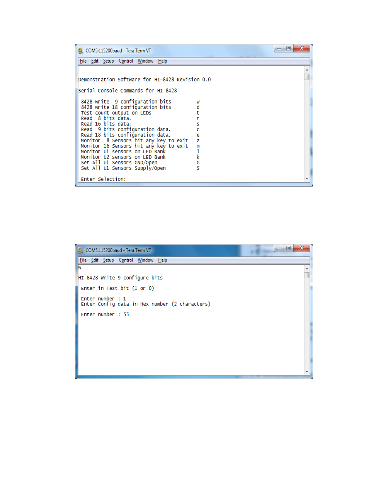
5. Theevaluationsoftwareispre‐programmedintotheMCUattheHoltApplicationsSupport
Center.EnsureallSW3switchesare‘ON’,pressthe‘RESETMCU’buttonontheboard,the
softwaredisplaysamessageonthemonitor,similartothescreenshotshownbelow.

QSG‐8428‐RRev.AHOLTINTEGRATEDCIRCUITSOct2014
9
6. Note:Ifunderanycircumstances,thissoftwarelocksup,usethe‘RESET’keytorecover.
7. Presskey‘t’toperformanLEDtest.TheSensor1‐8LEDsandscreenshouldgothrougha
binarycount.Tosetatestdataconfiguration;presskey‘w’towrite9configurationbits,
enter1then55,asshowninthescreenbelow:

QSG‐8428‐RRev.AHOLTINTEGRATEDCIRCUITSOct2014
10
8. Presskey‘c’toreadconfiguration.Thevaluesyouprogrammed(testbit1,config=0x55)
shouldbedisplayedasshowninthescreenbelow:
9. Whenthetestbitissetto‘1’,testdatacanbeplacedintothedatabufferthroughtheSPI
bus,thisisatestfeaturewhichtestsalargeportionofthedevice,butnotthecomparator
andthresholdsettingcircuits.Presskey‘r’toreaddata,onlythetestdatashouldnowbe
read,asshownbelow:
10. ToconfigureallU1sensorsasGND/Openpresskey‘w’andsettestbitto0,thenenterFF.
Press‘c’toreadregistersbacktothescreenandverifythattheconfigurationreads;
00xFF
All8sensorsarenowsettodetecttheGND/Openstates.Theshortcutkeys‘G’and‘S’canalso
beusedthesetallsensorstoGND/OpenandSupply/Openrespectively.

QSG‐8428‐RRev.AHOLTINTEGRATEDCIRCUITSOct2014
11
11. AquicktestoftheinputscanmadeusingDIPswitchSW1,presskey‘G’tosetGND/Open
mode,thenkey‘l’and‘A’.WiththejumperSENSOR_BANK_U1inposition1,setallswitches
toON,thissetsallinputstoGNDlevel.NowopenswitchSW1/1,SENSE1LEDshouldlight.
Carryonopeningtherestoftheswitches,eachcorrespondingLEDshouldnowlight.
12. ThesametestcanbedoneforSupply/Open,setjumperSENSOR_BANK_U1INposition3,
applyavoltageof15VtothetestpointnexttoJ3.SetallswitchestoOFF,thissetsallinputs
toOpenlevel.NowcloseswitchSW1/1,SENSE1LEDshouldlight.Carryonclosingtherestof
theSW1switches,eachcorrespondingLEDshouldnowlight.
TestingSenseThresholds
1. InGND/Openmode,VGTHLis4.5VminandVGTHHis10.5Vmax.Thiscanbetestedby
connectingavoltagesourcetotheSensorinputpinonconnectorsJ4andJ7.Makesureall
SW1DIPswitchesareintheOFFposition.Connectavariablevoltagesource(initiallysetto
0V)toJ4pin1,thistestsSensor1ofU1.Usetheshortcut‘G’keytoprogramallU1sensors
toGND/Open,pressthe‘l’keyandthenselect‘0’forsensor1,thescreenshouldscrollas
shownbelow,thiscontinuallymonitorstheU1sensorbank.
2. ThescreenaboveismonitoringU1sensor1,0xFEmeanssensors2to7bitsareata‘1’,in
GND/Open,andthismeansOpensaredetected(≥10.5V).Becausesensor1isheldat0Vthe
lastbitreads‘0’oraClosedstate(≤4.5V).Nowincreasethevoltagesourceupto9V,increase
thevoltageslowly,at10.5V,LED1ontheboardshouldbelit,thescreenshouldnowread
0xFFinsteadof0xFE.Nowdecreasethevoltage,LED1shouldgooffbefore4.5Visreached.
3. Pressanykeythenpresskey‘S’tosetallsensorstoSupply/Openmode.Pressthe‘l’keyand
thenselect‘0’forsensor1,thescreenshouldscrollasbeforebelowbutdisplaying0x00,
LED1‐8shouldbeoff.Againfrom0V,slowlyincreasevoltageuntilLED1islit,thisvoltage
shouldbe≤12V,nowdecreasethevoltage,LED1shouldgooffbefore6Visreached.

QSG‐8428‐RRev.AHOLTINTEGRATEDCIRCUITSOct2014
12
4. Anindividualsensorcanalsobemonitoredfromthehardwaretriggeroutput,byconnecting
totheSenseTriggertestpoint.Thisoutputcanbeusedtomeasurehighandlowthresholds
byinputtingarampvoltagetothesensorandthenmonitoringthisonanoscilloscope,the
testpointisusedtotriggertheoscilloscopeoftheSPImotherboard,whenthesensor
changesstate;sodoesthelevelonsensortrigger.
DaisyChainedSPIMode
1. TwoHI‐8428‐Rdevicesareprovidedontheevaluationboard,thisallowsthe‘daisychained’
featuretobeevaluated.U1andU2arelinkedtogetherthroughtheSPIconnections;theSO
pinofU1islinkedtotheSIpinofU2.Thesoftwarehascommandsthatprogramandread
bothdevicesusingthisfeature.
2. Presskey‘d’write1,AA,1,55,presskey‘e’,thescreenbelowshouldbeseen.
Theconfigurationregisterofbothdeviceshasbeensetandreadbackthroughthedaisychain
link.
3. ConfiguretheboardwithjumpersSENSEBANK_U1andSENSEBANK_U2isinthe‘1’position,
presskey‘d’andprogram0,FF,0,FF,allsensorsarenowprogrammedtoGND/Open.Setall
SW1,2switchesto‘ON’.
4. Presskey‘m’,thescreenshouldscrollthrough,showingthesensordata0x000x00foreach
device,setSW1to0x55andSW2to0xAApositionsandobservethecorrespondingchange
onthescreen.Seeexamplescreenbelow.
5. The‘k’commandcanbeusedtoreadjusttheU2sensorsandmonitortheseontheSENSE1‐8
LEDs,inthesamewaythe‘l’commandisusedforU1.Presskey‘k’andthen‘A’theLEDs
shouldread‘10101010’andtheBANK2LEDshouldbelit.

QSG‐8428‐RRev.AHOLTINTEGRATEDCIRCUITSOct2014
13
Connectingexternalsensors
Toconnectanexternalsensor,firstmakesurethecorrespondingDIPswitches(SW1‐2)arein
the‘OPEN’state.ThesensorwirescanbeconnectedtotheboardonthepinheadersJ4forU1
andJ7forU2,seetablebelow.
Pin
Number
J4
U1
J7
U2
1Sensor1Sensor1
2Sensor2Sensor2
3Sensor3Sensor3
4Sensor4Sensor4
5Sensor5Sensor5
6Sensor6Sensor6
7Sensor7Sensor7
8Sensor8Sensor8
9GNDGND
Connectionpinsforexternalsensors
LightningTests
Theboardcomesfittedwitha3kΩresistoroneachsensorinput;theseresistorsarenot
designedtosurvivealightningtest.Iflightningtestsaretobeperformed,pleaseuseaboard
designedforthisandwiththerecommendedresistor,contactHoltSupportforguidanceonthis.

QSG‐8428‐RRev.AHOLTINTEGRATEDCIRCUITSOct2014
14
ExternalSPIOperation
TheHI‐8428‐Rdevicesarenormallycontrolledthroughtheon‐boardMCU.Ifrequired,an
externalSPImasterconnectedtoJ10canbeused.WhenusingthismethodclosejumperJ11to
holdtheMCURESETpinlow,thisforcestheMCUGPIOsintoahighimpedancestate.Fornormal
operation,keepthisjumperopenandusetheRESETbuttontoresettheMCUduringtesting.
PowershouldbeconnectedbetweentheVDDterminalandground.TheSPIcontrollershould
thenbeconnectedtoJ10,usingthefollowingpinconnections:
SPIConnector(J10)
Pin
Number
LabelDescription
2SO1SPISerialOutputofU1
4SELSelectInputofU1andU2
6nCSSPIChipSelectforU1andU2
8SOSPISerialOutputfromU2
10SISPISerialDataInputtoU1
12SCKSPISerialClockInput
14VDD12to16.5Vsupply
163V33.3Vsupply
OddNosSupplyGround(0V)GND
J11connectionpins,forexternalSPI

QSG‐8428‐RRev.AHOLTINTEGRATEDCIRCUITSOct2014
15
LED6 R18
680 R19
680
LED7
LED8 R20
680
PE5
SENSOR BANK U1
J3
VSENSE 1
1
2
3
3214
ON(CLOSED)
85 6 7
SW1
TP2
SO
SENSOR BANK U2
nCS
SO1
J4
1
2
3
4
5
6
7
8
9
VSENSE BANK U1
J7
1
2
3
4
5
6
7
8
9
VSENSE BANK U2
R24 3k
R28 3k
R25 3k
R26 3k
R27 3k
R23
3k
R29 3k
R30 3k
TP7
SENSE TRIGGER
J6
VSENSE 2
1
2
3
TP8
3214
ON(CLOSED)
85 6 7
SW2
TP5
TP9
U2
8428 SO16
SENSE1 1
SENSE2 2
SENSE3 3
SENSE4 4
SENSE5 5
SENSE6 6
SENSE7 7
SENSE8 8
SO
9
SCK
10
CS
11
SI
12
SEL
13
VLOGIC
14
GND
15
VDD
16
PE4
3214
UP = O PEN ( HI G H)
SW3
TP10
R1
680
LED11
POWER
SO
+
C3
10uF,50V
TP1
LED12
POWER
R10
2k
C7
.1uF, 50V
+
C6
22uF,50V
TP3
J1
VLOGIC
1
2
nCS
SO1
SCK
SISI
SCK
SCK
3V3
VDD
VLOGIC
C14
.1uF
5V
nCS
SEL
GND
VLOGIC
SEL
nRESET
C23
.1uF
RESET
MICRO
SEL
SW4
VLOGIC
PE5
nRESET
BKGD
R33
3.3K
DEBUG HDR
VLOGIC
J9
HEADER 2X3
1 2
3 4
5 6 C24
.1uF
R34 220K
R35 27R
R36 27R
SEL
C11
.1uF
L1
F-BEAD 1.4A
YELLOW
+
C1
68uF 16V
VLOGIC
C2
.1uF
TP4
TP6
3V3
nCS
SPI BO A RD
INTERFACE
SO
SI
J10
2
4
6
8
10
12
14
16
1
3
5
7
9
11
13
15
Title
Size Document Num ber Rev
Dat e: Sheet of
<Doc> <RevCode>
HI-8428 -R, 8 Input Discrete with SPI - Engineering Board
B
14Thursday , September 18, 2014
J11
12
SO1
MINI-USB
"HOLD IN
RESET"
J8 USB_MINI_B_0
VCC 1
D- 2
D+ 3
GND 5
NC 4
CASE 6
C4
.1uF
VCC3O
VCC3O
USBDP
USBDM
U3
FT231XS-R
TXD
20
DTR#
1
RTS#
2
VCCIO
3
RXD
4
RI#
5
GND
6
DSR#
7
DCD#
8
CTS#
9
CBUS3
19
CBUS0
18
CBUS1 17
VCC 15
CBUS2 10
RESET# 14
GND 16
3V3OUT 13
USBDM 12
USBDP 11 C20
0.1uF
**
**
5V
USBDP
USBDM
FB1
FERRITE BEAD
1 2
C22
10nF
C25
47pF
C26
47pF
TXD0
RXD0
J2
U1_VDD
1
2VDD
RED
C12
.1uF
SCK
J12
U2_VDD
1
2VDD
PE4
PE2
PE3
J13
U2_VLOGIC
1
2VLOGIC
Notes:
1. There should be no traces under the SENSE[1:8] lines
of U1 and U2 to prevent inductive pick up during the lighting test, this
incudes the GND and power planes
PE2
PE3
GRN
RED
C5
.1uF
LED10R38
680 R11
680
LED1
U1
8428 SO16
SENSE1 1
SENSE2 2
SENSE3 3
SENSE4 4
SENSE5 5
SENSE6 6
SENSE7 7
SENSE8 8
SO
9
SCK
10
CS
11
SI
12
SEL
13
VLOGIC
14
GND
15
VDD
16
R37
680
LED9
R12
680
LED2
BANK U2
BANK U1
R15
680
LED3
BKGD
C21
220nF
R32
4.7K 1%
nRESET
R13
10k
R4 3k
R6 3k
R3 3k
R5 3k
U4
MC9S12XDT512CAA
SS1/PP3 1
SCK1/PP2 2
MOSI1/PP1 3
MISO1/PP0 4
IOC0/PT0
5IOC1/PT1
6IOC2/PT2
7IOC3/PT3
8
VDD1 9
VSS1 10
IOC4/PT4
11 IOC5/PT5
12 IOC6/PT6
13 IOC7/PT7
14
MODC/BKGD
15
PB0 16
PB1 17
PB2 18
PB3 19
PB4 20
PB5 21
PB6 22
PB7 23
XCLKS/PE7
24 PE6
25 PE5
26 ECLK/PE4
27
VSSR1 28
VDDR1 29
RESET 30
VDDPLL
31
XFC
32
VSSPLL
33
EXTAL
34
XTAL
35
TEST 36
PE3
37 PE2
38 IRQ/PE1
39 XIRQ/PE0
40
PA0 41
PA1 42
PA2 43
PA3 44
PA4 45
PA5 46
PA6 47
PA7 48
VDD2 49
VSS2 50
PAD00/AN00 51
PAD01/AN01 52
PAD02/AN02 53
PAN03/AN03 54
PAD04/AN04 55
PAD05/AN05 56
PAD06/AN06 57
PAD07/AN07 58
VDDA 59
VRH 60
VRL 61
VSSA 62
PS0/RXD0
63 PS1/TXD0
64 PS2/RXD1
65 PS3/TXD1
66
VREGEN 67
PJ7
68 PJ6
69
SCK0 70
MOSI0 71
SS0 72
MISO0 73
PM1/TX
74 PM0/RX
75
VSSX 76
VDDX 77
SCK2
78 MOSI2
79 MISO2
80
R7 3k
R2
3k
R14
10k
R8 3k
C13
10pF
R9 3k
C8
10pF
C18
220nF
Y1
4MHz
C19
220nF
VLOGIC
C9
220nF C10
220nF
VLOGIC
VLOGIC
RXD0
C15
220nF
C17
.01uF
C16
470pF
TXD0
R22
1 Mohm
R16
680
LED4 LED5 R17
680

QSG‐8428‐RRev.AHOLTINTEGRATEDCIRCUITSOct2014
16
Bill of Materials HI-8428-R Evaluation Board Revised: 09/12/13
Qty Description Reference DigiKey Mfr P/N
1 PCB, Bare, Evaluation Board N/A Jet Tech # 36602
1 Capacitor 68uF,20%, 16V Tant SMD C1 495-2254-1-ND Kemet
T491D686M016ZT
10 Capacitor, Cer 0.1uF 20% 50V Z5U 0805 C2,C4,C5,C7,C11,C12,C14,C20,C23,C2
4 399-1176-1-ND Kemet
C0805C104M5UACTU
1 CAP ALUM 10UF 50V 20% SMD C3 493-9998-1-ND Nichicon
UWZ1H100MCL1GB
1 CAP ALUM 22UF 50V 20% SMD C6 493-6180-1-ND Nichicon
UCD1H220MCL1GS
2 Capacitor, Cer 10pF 50V 5% NP0 0805 C8,C13 399-1108-1-ND Kemet
C0805C100J5GACTU
6 Capacitor, Cer .22uF 10% 50V X7R 0805 C9,C10,C15,C18,C19,C21 399-3491-1-ND Kemet
C0805C224K5RACTU
1 Capacitor, Cer 470pF 50V 5% X7R 0805 C16 399-1133-1-ND Kemet
C0805C471J5GACTU
2 Capacitor, Cer 0.01uF 20% 50V 7XR 0805 C17,C22 399-1160-1-ND Kemet
C0805C103M5RACTU
2 Capacitor, Cer 47pF 50V 5% NP0 0805 C25,C26 399-1117-1-ND Kemet
C0805C470J5GACTU
1 Ferrite 330 Ohm@100MHz 0805 FB1 490-5988-1-ND Murata
BLM21PG331SN1D
1 Ferrite 220 Ohm @100 MHz 0805 L1 490-1054-1-ND Murata
BLM21PG221SN1D
5 Conn Header .100 SGL STR 2Pos Holt On Reset, U1-Logic, U1_VDD,
U2_Logic, U2_VDD S1012E-02-ND Sullins PEC02SAAN
2 Conn Header .100 SGL STR 3Pos J3,J6 S1012E-03-ND Sullins PEC03SAAN
2 Conn Header .100 SGL STR 9Pos J4,J7 S1012E-09-ND Sullins PEC09SAAN
7 Conn Jumper Shorting .100" Tin 7 locations S9341-ND Sullins NPC02SXON-
RC
1 Header, Male 0.1", Right Angle 2 x 3 Debug Header S2312E-06-ND Sullins PEC36DGAN
1 Conn Receptacle Mini USB2.0 5Pos J8 H2959CT-ND Hirose UX60-MB-5ST
1 Header, Male 2x8 0.1" Pitch, 0.230"/0.120" Tails J10 S2012E-08-ND Sullins PEC08DAAN

QSG‐8428‐RRev.AHOLTINTEGRATEDCIRCUITSOct2014
17
10 LED Green 0805 LED1- LED11 160-1179-1-ND LiteOn LTST-C170GKT
1 LED Red 0805 LED12 160-1178-1-ND LiteOn LTST-C170EKT
11 Res 680, 1/8W 5% 0805 SMD R1,R11,R12,R15,R16,R17,R18,R19,
R20,R37,R38 P680ACT-ND Panasonic ERJ-
6GEYJ681V
16
Res 3K, 1/8W 5% 0805 SMD R2,R3,R4,R5,R6,R7,R8,R9,R23,R24,R25
,R26,
R27,R28,R29,R30
P3.0KACT-ND Panasonic ERJ-
6GEYJ302V
1 Res 2.0K, 1/8W 5% 0805 SMD R10 P2.0KACT-ND Panasonic ERJ-
6GEYJ202V
2 Resistor, 10K 5% 1/8W 0805 R13,R14 P10KACT-ND Panasonic ERJ-
6GEYJ103V
1 Res 1M, 1/8W 5% 0805 SMD R22 P1MACT-ND Panasonic ERJ-
6GEYJ105V
1 Res 4.7K, 1/8W 1% 0805 SMD R32 P4.7KACT-ND Panasonic ERJ-
6GEYJ472V
1 Res 3.3K, 1/8W 5% 0805 SMD R33 P3.3KACT-ND Panasonic ERJ-
6GEYJ332V
1 Resistor, 220K 5% 1/8W 0805 R34 P220KACT-ND Panasonic ERJ-
6GEYJ224V
2 Res 27, 1/8W 5% 0805 SMD R35,R36 P27ACT-ND Panasonic ERJ-
6GEYJ270V
2 Switch Tape Seal 8 Pos SMD 50V SW1,SW2 CT2198MST-ND CTS 219-8MST
1 Switch Tape Seal 4 Pos SMD 50V SW3 CT2194MST-ND CTS 219-4MST
1 Switch Tactile SPST-NO 0.05A 32V RESET P12943SCT-ND Panasonic EVQ-
Q2K03W
1 Test Point, Red Insulator, 0.062" 3V3 5010K-ND Keystone 5012
1 Test Point, Orange Insulator, 0.062" VDD 5013K-ND Keystone 5013
1 Test Point, White Insulator, 0.062" Sense Trigger 5012K-ND Keystone 5012
2 HI-8428-R 16-SOIC U1,U2 HI-8428-R HI-8428-R SOIC16
1 IC USB SERIAL FULL UART 20SSOP U3 768-1129-1-ND FTD FT231XS-R
1 IC, MC9S12XDT512CAA 80 QFP 16-Bit MCU,
512K Flash 0-70C U4 MC9S12XDT512
CAA-ND MC9S12XDT512CAA
1 Crystal 4.00MHz, SMD, 50ppm 20pF Y1 631-1005-1-ND FOXSDLF/040

QSG‐8428‐RRev.AHOLTINTEGRATEDCIRCUITSOct2014
18
REVISIONHISTORY
Revision Date Description of Change
QSG-8428-R, Rev.
New 9-12-14 New
QSG-8428-R, Rev. A 10-1-14 New board (SW1, SW2 location moved on schematic)
Table of contents
Other HOLT Motherboard manuals