HOLT ADK-8400 User manual

QSG-8400 Rev. New Holt Integrated Circuits
ADK-8400 Evaluation Board
Quick Start Guide:
HI-8400 Isolated Discrete Sensor
with ±800V Isolation
July 2018

REVISION HISTORY
Revision
Date
Description of Change
QSG-8400, Rev. New
07-25-18
Initial Release

Holt Integrated Circuits
3
Introduction
This board allows the customer to evaluate the features of the galvanically isolated HI-8400 four channel
discrete sensor IC. Each input has full isolation from the digital domain and from the other sensor inputs.
The HI-8400 logic is powered from a single 3.3V ±5% or 5V ±5% supply voltage. The isolated analog
sensor input is supplied from a 16 to 36VDC supply. Each input channel can be individually configured as
a GND/Open or Supply/Open Sensor type using hardware pins. Sensor thresholds are internally set at
Airbus ABD0100H levels, an SPI port is used to read sensor data. A second board is also included to allow
users to evaluate the daisy chain feature.
Figure 1 –Top View of HI-8400 Evaluation Set Up including Daisy Chain Board

Holt Integrated Circuits
4
WARNING –Before using High Voltage equipment ensure that you use
the best safety operating practices, including, but not limited to the
following precautions :
Do NOT work with high voltage by yourself, have another person (safety
observer), qualified in first aid for electrical shock, present at all times.
Use rubber gloves where applicable and stand on approved
rubber matting. Note that not all so-called rubber mats are good isolators.
Always discharge the high voltage from components or terminals by using
a safety probe. Do NOT hold the test probe when circuits over 300 volts
are tested.
Always use equipment certified for operation at or above the peak
voltages being tested.

Holt Integrated Circuits
5
KIT CONTENTS
●This User Guide.
●HI-8400 Evaluation Board.
●USB Flash drive with HI-8400 software
●USB to Mini USB Serial Cable.
Demonstration Set-up

Holt Integrated Circuits
6
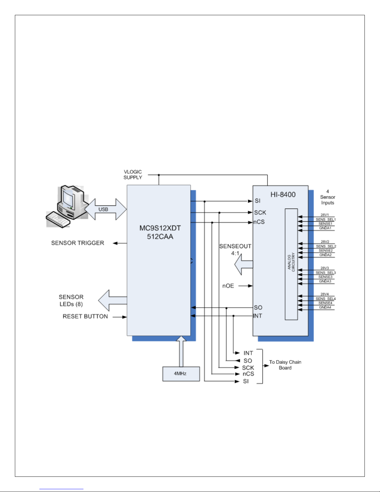
Initial Board Set up
1. Make sure the board jumpers and switch positions match the default settings listed earlier.
The VLOGIC supply can also use a 3.3V or 5V supply, in the case of 5V there is the option of
using the USB supply by linking jumper J12 (this is the default set up), if you are not using
the USB supply J12 should be open. If using an external supply then connect a +3.3V or +5V
power supply to VLOGIC (RED) and 0V to GND terminals making sure J12 is open.
2. Each input channel of the HI-8400 is in its own isolated domain, the sensor type for each
input is set by control pins, these are referenced only to the GND of that input; there is no
common ground for the sensors inputs. Of course if desired all the sensor grounds of the
device can be connected together. To set an input to GND/Open the SENS_SELx input for
channelx must be connected to the GNDAx of that same channel. To set an input to
Supply/Open the SENS_SELx input for that channel must be connected to the 28Vx of that
same channelx. Jumpers J4, 6, 11, 13 on the board are provided to do this.
3. Reading of the sense data can be on the dedicated hardware pins SENSEOUT[1:4] or through
the on board MCU, and interfacing with a terminal emulator. When using the
SENSEOUT[1:4] pins, the nOE pin has to be low to enable the outputs. LEDS SO[1:4] are
used to monitor these sensor outputs. In GND/Open an illuminated LED means that sensor
is Open (High). In Supply/Open sensor mode an illuminated LED means that sensor is closed
or at Supply level (High).
4. Each channel requires its own 28V supply, the positive and negatives of each supply should
be connected to the 28Vx and GNDAx to pins on J3, J8, J10 and J14. Alternatively, the
breakout board supplied with the kit can be used if a common GND and 28V is to be used
for all four sense channels.
Software Control
1. Connect the mini USB lead to your PC and then to the console connector J15 on the HI-8400
board; your PC should automatically install the driver. If not the driver FT231 can be installed
from the Holt Flash drive. If you have problems installing the driver, please refer to the FTDI
website below:
2. http://www.ftdichip.com/Documents/InstallGuides.htm

Holt Integrated Circuits
7
3. SPI data from the HI-8400 is read through the ‘Control Console’. This requires use of a
terminal emulator for communication, such as HyperTerminal or Tera Term. Tera Term is
used with Windows versions of Vista or later and is supplied on the Holt Flash drive.
To install Tera Term:
●Use the Tera Term installer, supplied on the Holt Flash drive; run the teraterm-
x.xx.exe installer program. Accept the license agreement stating redistribution is
permitted provided that copyright notice is retained. The notice can be displayed
from the Tera Term window by clicking Help then clicking About Tera Term.
●Accept the default install destination and click Next.
●At the Select Components screen, unselect all options except Additional Plugin =
TTXResizeMenu and click Next.
●Select the installed language, then click Next.
●Accept the default Start Menu folder, then click Next.
●Select any desired shortcuts, then click Next.
●At the Ready to Install screen, click Install.
Run the installed Tera Term program. At the New Connection screen, select (x)Serial and
choose the selected COM port, find the correct COM port using Device Manager.
4. Click Setup then Serial Port to open the serial port setup window. Choose the COM port for
the mini-USB connection and then select the following settings:
Baud Rate = 115200, Data = 8 bits, Parity = none, Stop = 1 bit, Flow Control = none.
5. The evaluation software is pre-programmed into the MCU at the Holt Applications Support
Center. Press the ‘RESET MCU’ button on the board, the general purpose LED bank, LED[1:8]
will light for 1 sec, the software revision is then displayed on the same LEDs, LED[8:5] being
the most significant digit and LED[4:1] being the least significant digit.
6. The software displays a message on the monitor, similar to the screenshot shown below.

Holt Integrated Circuits
8
5. Note: If under any circumstances, this software locks up, use the ‘RESET’ key to recover.
6. Press key ‘t’ to perform an LED test. The Sensor1-8 LEDs and screen start counting in Hex.
7. Press key ‘r’ to read the four sensors data, this will be displayed on the screen as shown
below:
This shows the binary output of each sensor, with sensor 1 first and sensor 4 last. If the
sensor input is high then the correlating sensor LED is lit on the LED array Sense 1:8, this
shows the sensor data read from SPI. LEDs S01 to S04 show the state of the devices hardwire
sense outputs. The display above shows sensor 1 in the high state and sensors 2-4 in low
state. To create this set up on the board just connect the 28V1 to 28V and GND1 to 0V, this
produces an Open (high) in the GND/Open sensor 1, the other sensors will default to ‘0’.
8. To continually monitor the four outputs then use the key ‘z’, this will show a screen similar to
below:

Holt Integrated Circuits
9
Monitoring the four sensors above, it can be seen that sensor 1 is high. Press any key to exit
this function.
Testing Sense Thresholds
1. In GND/Open mode, VGTHL is 4.5V min and VGTHH is 10.5V max. This can be tested by
connecting a voltage source to the Sensor1 input pins on connectors J3, J8, J10 and J14. Make
sure the ground connection is connected to the GND reference for this channel. Set the Sense
Input voltage to 0V, then press the short cut ‘z’ key to run the monitor program, all four sensors
U3 will be read in a loop, as shown below.
The screen above is monitoring U3 sensors, ‘0000’ means all sensors are reading low.
2. Now increase the voltage source up to 9V, then increase the voltage slowly, to 10.5V, LED1
and LED S1 on the board should be lit, the screen should now read 1000, as shown below:

Holt Integrated Circuits
10
Now decrease the voltage, LED1 and S01 should go off before 4.5V is reached and the screen
should go back to reading 0000.
3. To measure the Supply/Open thresholds follow the following procedure. Set sensor type to
Supply/Open by connecting a jumper between S and V (pins 2 and 3) on J26. Using a
procedure similar to 1. Connect a supply to the sensor input and adjust to 0V, press key ‘z’ ,
the screen should read ‘0000’ as shown below:
4. Increase the voltage source up to 10.5V, then increase the voltage slowly, to 12V, LED1 and
LED S1 on the board should be lit, the screen should now read 1000, as shown below:

Holt Integrated Circuits
11
Now decrease the voltage, LED1 and S01 should go off before 6V is reached and the screen
should go back to reading 0000.
5. An individual sensor can also be monitored from the INTB output to provide a hardware
trigger, connect an oscilloscope probe to the INTB test point. Use this output as a trigger to
an oscilloscope, input a ramp voltage to the sensor and monitor the ramp on another
channel of the oscilloscope. When the sensor changes the INTB signal triggers the
oscilloscope the negative edge of INTB will cross the ramp at the threshold point, allowing
easy measurement.
Daisy Chained SPI Mode
1. Two HI-8400 boards are provided with the evaluation kit. Board 1 is the master board with a
microprocessor to control the interface. Board2 is used for daisy chain testing and should be
plugged into Board1 at connector J7. The console option ‘m’, continually reads the SPI data
from both devices in the daisy chain configuration. To get active sensor data, the sensors on
board2 will need to be connected to a 28V supply and sensor voltage. Connector J7 links the
SPI connections of the two devices; the SO pin of Board1 is linked to the SI pin of Board2. The
software has commands that read both devices through the SO pin of Board2.

Holt Integrated Circuits
12
2. Press key ‘m’, a screen similar to the one below should be seen.
The sense data for Device1 on board1 and Device2 on board2 are displayed, a ‘1’ meaning a
high. Key ‘s’ can be used to just do one read. LED[1:8] also monitor the eight input states.
External SPI Operation
The HI-8400 devices are normally controlled through the on-board MCU. If required, an external
SPI master connected to J7 can be used. When using this method close jumper J1 to hold the
MCU RESET pin low, this forces the MCU GPIOs into a high impedance state. For normal
operation, keep this jumper open and use the RESET button to reset the MCU during testing.
Power should be connected between the VDD terminal and ground. The SPI controller should
then be connected to J7, using the following pin connections:
SPI Connector (J7)
Pin
Number
Label
Description
1
VLOGIC
3.3V or 5V Logic supply
2
nCS
SPI Chip Select
3
SCK
SPI Serial Clock Input
4
SI
SPI Serial Data Input
5
SO
SPI Serial Output from U3
6
INTB
Interrupt output from U3
7
GND
Low voltage Ground

Holt Integrated Circuits
13
Parallel Data out connector (J9)
Pin
Number
Label
Description
1
GND
Low voltage Ground
2
INTB
Interrupt output from U3
3
NC
Not Connected
4
nOE
Output Enable (active low)
5
SO1
Sense Output 1
6
SO2
Sense Output 2
7
SO3
Sense Output 3
8
SO4
Sense Output 4
Debug connector (for Freescale Processor) (J2)
Pin
Number
Label
Description
1
BKGD
Debug data
2
GND
Ground
3
NC
Not Connected
4
nRESET
Reset Target
5
NC
Not Connected
6
NC
Not Connected

Holt Integrated Circuits
14
Default Jumper Settings
JUMPER
POSITION
DESCRIPTION
J1
OFF
Link to hold microprocessor in Reset (to use ext SPI)
J4
2:1
Link 3:2 Selects 28V/Open type for Sensor 4
Link 2:1 Selects GND/Open type for Sensor 4
J5
ON
VLOGIC Link for supply current to U3 (disconnect to
measure HI-8400 VLOGIC supply current )
J8
2:1
Link 3:2 Selects 28V/Open type for Sensor 3
Link 2:1 Selects GND/Open type for Sensor 3
J10
2:1
Link 3:2 Selects 28V/Open type for Sensor 2
Link 2:1 Selects GND/Open type for Sensor 2
J14
2:1
Link 3:2 Selects 28V/Open type for Sensor 1
Link 2:1 Selects GND/Open type for Sensor 1
J12
OFF
Link to use USB 5V supply
J16
Open
Link 1:2 Selects non maskable interrupt
Link 2:3 Selects maskable interrupt
J31
Closed
Link 1:2 Enables SENSEOUT [1:4] OF U3

Holt Integrated Circuits
15
Daisy Chain Board Connections
SPI Connector (J28)
Pin
Number
Label
Description
1
VLOGIC
3.3V/ 5V Logic supply
2
nCS
SPI Chip Select
3
SCK
SPI Serial Clock Input of U4
4
SO
SPI Serial Output from U4
5
SI
SPI Serial Input of U4
6
INTB
Interrupt output from U4
7
GND
Low voltage Ground
Parallel Data out connector (J22)
Pin
Number
Label
Description
1
GND
Low voltage Ground
2
INTB
Interrupt output from U4
3
NC
Not Connected
4
nOE
Output Enable (active low)
5
SO1
Sense Output 1
6
SO2
Sense Output 2
7
SO3
Sense Output 3
8
SO4
Sense Output 4

Holt Integrated Circuits
16
Default Jumper Settings
JUMPER
POSITION
DESCRIPTION
J18
2:3
Link 1:2 Selects 28V/Open type for Sensor 4
Link 2:3 Selects GND/Open type for Sensor 4
J20
2:3
Link 1:2 Selects 28V/Open type for Sensor 3
Link 2:3 Selects GND/Open type for Sensor 3
J23
2:3
Link 1:2 Selects 28V/Open type for Sensor 2
Link 2:3 Selects GND/Open type for Sensor 2
J26
2:3
Link 1:2 Selects 28V/Open type for Sensor 1
Link 2:3 Selects GND/Open type for Sensor 1
J32
Closed
Link 1:2 Enables SENSEOUT [1:4] OF U4
Link 2:3 Selects GND/Open type for Sensor 1

5
5
4
4
3
3
2
2
1
1
D D
C C
B B
A A
Green
CHANNEL 4
CHANNEL 3
CHANNEL 2
CHANNEL 1
"HOLD IN
RESET"
DEBUG HDR
MINI-USB
**
HIGH VOLTAGE
AREA
SEL 4
SEL 3
SEL 2
SEL 1
Green
Green
Green
Green
Green
SENSE 1:8
Extended
OE
LINK FOR TO USE
USB 5V SUPPLY
VLOGIC
VCC3O
VCC3O
RXD0
BKGD
nRESET
RXD0
TXD0
SI
SCK
3V3
SO
nCS
TXD0
VLOGIC
28V2
SENSE2
GNDA2
SEL2
GNDA3
28V3
28V1
SENSE1
GNDA1
SEL1
VLOGIC
SENSE4
SEL3
SENSE3
GND
BKGD nRESET
GNDA4
28V4
SEL4
nRESET
INTB
SI
SO
nCS
SCK
INTB
SI
SO
SCK
nCS
VLOGIC
INTB
28V1
GNDA1
28V2
GNDA2
28V3
GNDA3
28V4
GNDA4
5V
VLOGIC
VLOGIC
VLOGIC
VLOGIC
VLOGIC
5V
5V
Title
Size Document Number Rev
Date: Sheet of
<Doc> A
HI-8400- 4 Input Discrete with Isolation - Main Board
Custom
12Thursday, June 07, 2018
Title
Size Document Number Rev
Date: Sheet of
<Doc> A
HI-8400- 4 Input Discrete with Isolation - Main Board
Custom
12Thursday, June 07, 2018
Title
Size Document Number Rev
Date: Sheet of
<Doc> A
HI-8400- 4 Input Discrete with Isolation - Main Board
Custom
12Thursday, June 07, 2018
C24
4.7uF
TP14
GND
LED3
C32
.1uF
LED9
POWER
R21
680
R1 100K
TP2
RXD0
C17
470pF
R12
27
J6
1
3
2
TP6
Int
LED4
R4
680
J10
SENSE2
1
2
3
4
TP3
TXD0
LED8
C25
4.7uF
C33
.1uF
C20 .1uF
R25
680
J1
12
TP10
VLOGIC
J8
SENSE3
1
2
3
4
TP7
GND
C26
4.7uF
C19
.1uF
C5
.1uF
R26
680
J15
VCC
1
D-
2
D+
3
GND
5
NC
4
CASE
6
C34
.1uF
J9
1
12
23
34
45
56
67
78
8
C6
.1uF
R13
10k
LED5
L1
F-BEAD 1.4A
R15
1K
SO3
R16
4.7K
R10
1M
J4
1
3
2
J31
12
C9
.1uF
U1
MC9S12XDT512CAA
SS1/PP3 1
SCK1/PP2 2
MOSI1/PP1 3
MISO1/PP0 4
IOC0/PT0
5IOC1/PT1
6IOC2/PT2
7IOC3/PT3
8
VDD1 9
VSS1 10
IOC4/PT4
11 IOC5/PT5
12 IOC6/PT6
13 IOC7/PT7
14
MODC/BKGD
15
PB0 16
PB1 17
PB2 18
PB3 19
PB4 20
PB5 21
PB6 22
PB7 23
XCLKS/PE7
24 PE6
25 PE5
26 ECLK/PE4
27
VSSR1 28
VDDR1 29
RESET 30
VDDPLL
31
XFC
32
VSSPLL
33
EXTAL
34
XTAL
35
TEST 36
PE3
37 PE2
38 IRQ/PE1
39 XIRQ/PE0
40
PA0 41
PA1 42
PA2 43
PA3 44
PA4 45
PA5 46
PA6 47
PA7 48
VDD2 49
VSS2 50
PAD00/AN00 51
PAD01/AN01 52
PAD02/AN02 53
PAN03/AN03 54
PAD04/AN04 55
PAD05/AN05 56
PAD06/AN06 57
PAD07/AN07 58
VDDA 59
VRH 60
VRL 61
VSSA 62
PS0/RXD0
63 PS1/TXD0
64 PS2/RXD1
65 PS3/TXD1
66
VREGEN 67
PJ7
68 PJ6
69
SCK0 70
MOSI0 71
SS0 72
MISO0 73
PM1/TX
74 PM0/RX
75
VSSX 76
VDDX 77
SCK2
78 MOSI2
79 MISO2
80
J16
INT SELECT
1
2
3
R14
1K
J13
1
3
2
SO4
C11
10pF
U3
HI-8400PQI
SEN_SEL4 44
SEN_SEL3
2
GNDA3
3
SENSE3
4
VDD28_3
5
NC2
6
VDD28_2
7
SENSE2
8
GNDA2
9
SEN_SEL2
10
SEN_SEL1
12
GNDA1
13
SENSE1
14
VDD28_1
15
NC4
16
NC5
17
NC6
18
NC7
19
NC8
20
NC9
21
NC10
22
INT 23
NC 24
SO 25
OE 26
SENSEOUT1 27
SENSEOUT2 28
SENSEOUT3 29
SENSEOUT4 30
SCK 31
CS 32
SI 33
VLOGIC 34
GNDL 35
NC11 36
NC12 37
NC13 38
NC15 39
NC16 40
VDD28_4 41
SENSE4 42
GNDA4 43
NC1
1
NC3
11
U2
FT231XS-R
TXD
20
DTR#
1
RTS#
2
VCCIO
3
RXD
4
RI#
5
GND
6
DSR#
7
DCD#
8
CTS#
9
CBUS3
19
CBUS0
18
CBUS1 17
VCC 15
CBUS2 10
RESET# 14
GND 16
3V3OUT 13
USBDM 12
USBDP 11
+
C4
10uF,16V
TP13
GND
J11
1
3
2
R17
1K
J5
12
C10
.1uF
R22
680
+
C1
68uF 16V
C21
.1uF
J3
SENSE4
1
2
3
4
LED1
TP8
GND
C18
.1uF
C14
.01uF
TP1
3V3
J14 SENSE1
1
2
3
4
R19
680
C7
.1uF
R5
3.3K
C8
10pF
R23
680
FB1
FERRITE BEAD
1 2
TP5
Sense Trigger
LED6
C15
.01uF
J7
11
22
33
44
55
66
77
R18
1K
LED2
C12 47pF
SO2
J2
HEADER 2X3
1 2
3 4
5 6
C23
4.7uF
LED7
J12
1 2
+
C39
10uF,16V
SW1
Reset Micro
C16
.1uF
C31
.1uF
R11
27
C13 47pFSO1
R24
680
Y1
4MHz
C2
.1uF
R20
680
C3
.1uF

5
5
4
4
3
3
2
2
1
1
D D
C C
B B
A A
CHANNEL 2
SEL 4
HIGH VOLTAGE
AREA
SEL 3
SEL 2
CHANNEL 1 Green
SEL 1
Green
CHANNEL 3
Green
Extended
Green
CHANNEL 4
VLOGIC
OE
VLOGIC
SENSE4
28V4
SEL4
GNDA4
SI
nCS
SCK
SO
28V3
SENSE3
GNDA3
SEL3
28V2
SENSE2
INTB
GNDA2
SEL2
VLOGIC
SEL1
GNDA1
SENSE1
28V1
INTB
SO
SI
SCK
nCS
VLOGIC
28V4
GNDA4
28V3
GNDA3
28V2
GNDA2
28V1
GNDA1
Title
Size Document Number Rev
Date: Sheet of
<Doc> A
HI-8400 4-Input Discrete with Isolation - Daisy Chain Board
Custom
22Thursday, May 17, 2018
Title
Size Document Number Rev
Date: Sheet of
<Doc> A
HI-8400 4-Input Discrete with Isolation - Daisy Chain Board
Custom
22Thursday, May 17, 2018
Title
Size Document Number Rev
Date: Sheet of
<Doc> A
HI-8400 4-Input Discrete with Isolation - Daisy Chain Board
Custom
22Thursday, May 17, 2018
SO7
J23
SENSE2
1
2
3
4
J21
SENSE3
1
2
3
4
R28
1K SO5
R31
1K
J20
1
3
2
SO8
C27
4.7uF
J32
12
C35
.1uF
J26
1
3
2
R29
1K
C28
4.7uF
C36
.1uF
J22
1
12
23
34
45
56
67
78
8
J17
SENSE4
1
2
3
4
SO6
C29
4.7uF
C37
.1uF
TP12
GND
TP11
Int
+
C40
10uF,16V
C22
.1uF
J27 SENSE1
1
2
3
4
C30
4.7uF
J28
11
22
33
44
55
66
77
R27
10k
C38
.1uF
J18
1
3
2
U4
HI-8400PQI
SEN_SEL4 44
SEN_SEL3
2
GNDA3
3
SENSE3
4
VDD28_3
5
NC2
6
VDD28_2
7
SENSE2
8
GNDA2
9
SEN_SEL2
10
SEN_SEL1
12
GNDA1
13
SENSE1
14
VDD28_1
15
NC4
16
NC5
17
NC6
18
NC7
19
NC8
20
NC9
21
NC10
22
INT 23
NC 24
SO 25
OE 26
SENSEOUT1 27
SENSEOUT2 28
SENSEOUT3 29
SENSEOUT4 30
SCK 31
CS 32
SI 33
VLOGIC 34
GNDL 35
NC11 36
NC12 37
NC13 38
NC15 39
NC16 40
VDD28_4 41
SENSE4 42
GNDA4 43
NC1
1
NC3
11
R30
1K
J24
1
3
2

Holt Integrated Circuits, Inc.
PCB P/N: HE035
Bill of Materials
HI-8400 4-Input Discrete Evaluation Board
Rev. A
May 21, 2018
1
2
3
4
5
6
7
8
9
10
11
12
13
14
15
16
17
18
19
20
21
22
23
24
25
26
27
28
29
30
31
32
33
34
35
36
37
38
39
40
41
42
A B C D E F
Item Qty
Description Reference Digikey P/N Mfg P/N
1 1 PCB, Bare, Evaluation Board N/A Jet Tech 42737
2 1 Capacitor 68uF,20%, 16V Tant SMD 6032 C1 399-8399-1-ND Kemet T491D686M016AT
3 2 Capacitor 10uF,20%, 16V Tant SMD 6032 C4,C39 399-3732-1-ND Kemet T491C106K016AT
4 8 Capacitor, Cer 4.7uF 10% 50V X5R 0805 C23-C30 490-10751-1-ND Murata GRM21BR61H475KE51L
520 Capacitor, Cer 0.1uF 20% 50V Z5U 0805
C2,C3,C5-C7,C9,C10,C16,
C18-C22,C31-34,C35-C38
399-1176-1-ND Kemet C0805C104M5UACTU
6 2 Capacitor, Cer 0.01uF 20% 50V 7XR 0805 C14,C15 399-1160-1-ND Kemet C0805C103M5RACTU
7 2 Capacitor, Cer 10pF 50V 5% NP0 0805 C8,C11 399-1108-1-ND Kemet C0805C100J5GACTU
8 2 Capacitor, Cer 47pF 50V 5% NP0 0805 C12,C13 399-1117-1-ND Kemet C0805C470J5GACTU
9 1 Capacitor, Cer 470pF 50V 5% X7R 0805 C17 399-1133-1-ND Kemet C0805C471J5GACTU
10 1 Ferrite 330 Ohm@100MHz 0805 FB1 490-5988-1-ND Murata BLM21PG331SN1D
11 1 Ferrite 220 Ohm, 2A @100 MHz 0805 L1 490-1054-1-ND Murata BLM21PG221SN1D
12 3 Conn Header .100 SGL STR 2Pos J5,J12,J19 S1012E-02-ND Sullins PEC02SAAN
13 11 Conn Header .100 SGL STR 3Pos
J4,J6,J11,J13,J16,J18,
J20,J24, J26, J31,J32
S1012E-03-ND Sullins PEC03SAAN
14 8 Conn Header .100 SGL STR 4Pos
J3,J8,J10,J14,J17,
J21,J23,J27
S1012E-04-ND Sullins PEC04SAAN
15 2 Conn Header .100 SGL STR 8Pos J9,J22 S1012E-08-ND Sullins PEC08SAAN
16 1 Conn Header .100 SGL R/A 7 Pos Female J7 S5482-ND Sullins PPPC071LGBN-RC
17 1 Conn Header .100 SGL R/A 2 Pos Male J1 S1111E-02-ND Sullins PBC02SBAN
18 1 Conn Header .100 SGL R/A 7 Pos Male J28 S1111E-07-ND Sullins PBC07SBAN
19 12 Conn Jumper Shorting .100" Gold
J4,J5,J6,J11,J12,J13,J18,
J19,J20,J24, J25,J26
S9001-ND Sullins SPC02SYAN
20 1 Header, Female 0.1", Right Angle 2 x 3 Debug Header S5556-ND SullinsPPPC032LJBN-RC
21 1 Conn Receptacle Mini USB2.0 5Pos J15 H2959CT-ND Hirose UX60-MB-5ST
22 17 LED Green SMD 0805 SO1-SO8, LED1-LED9 160-1179-1-ND LiteOn LTST-C170GKT
23 2 Res 27, 1/8W 5% 0805 SMD R11,R12 P27ACT-ND Panasonic ERJ-6GEYJ270V
24 9 Res 680, 1/8W 5% 0805 SMD R4,R19-R26 P680ACT-ND Panasonic ERJ-6GEYJ681V
25 8 Res 1K, 1/8W 5% 0805 SMD
R14,R15,R17,R18,
R28,R29,R30,R31
P1.0KACT-ND Panasonic ERJ-6GEYJ102V
26 1 Res 4.7K, 1/8W 1% 0805 SMD R16 P4.7KACT-ND Panasonic ERJ-6GEYJ472V
27 1 Res 3.3K, 1/8W 5% 0805 SMD R5 P3.3KACT-ND Panasonic ERJ-6GEYJ332V
28 2 Res 10K 5% 1/8W 0805 R13,R27 P10KACT-ND Panasonic ERJ-6GEYJ103V
29 1 Res 100K, 1/8W 5% 0805 SMD R1 P100KACT-ND Panasonic ERJ-6GEYJ104V
30 1 Res 1M, 1/8W 5% 0805 SMD R10 P1MACT-ND Panasonic ERJ-6GEYJ105V
31 1 Switch Tactile SPST-NO 0.02A 15V SW1 P12943SCT-ND Panasonic EVQ-Q2K03W
32 1 Test Point, Red Insulator, 0.062" TP1 (3V3) 36-5010K-ND Keystone 5010
33 5 Test Point, Black Insulator, 0.062" TP8,TP12-TP15 (GND) 36-5011K-ND Keystone 5011
34 1 Test Point, Orange Insulator, 0.062" TP10 (VLOGIC) 36-5013K-ND Keystone 5013
35 5 Test Point, White Insulator, 0.040"
TP2,TP3,TP5,TP6,
TP11 - DNI
36-5002-ND Keystone 5002
36 2 HI-8400PQ 44-QFP U3,U4 HI-8400PQ HI-8400PQ 44-QFP
37 1 IC USB SERIAL FULL UART 20SSOP U2 768-1129-1-ND FTD FT231XS-R
38 1
IC, MC9S12XDT512CAA 80
QFP 16-Bit MCU, 512K Flash 0-70C
U1 MC9S12XDT512CAA-ND MC9S12XDT512CAA
39 1 Crystal 4.00MHz, SMD, 50ppm 20pF Y1 631-1005-1-ND FOXSDLF/040
40 6 Rubber Foot, Bumpon Black, .312 X.200 H Place at the mounting holes SJ5746-0-ND 3M SJ61A1
Other manuals for ADK-8400
1
Table of contents
Other HOLT Motherboard manuals