HOLT ADK-620x3 User manual

AN-62003 Rev. A Holt Integrated Circuits
ADK-620x3 User’s Guide:
Evaluation Board for
HI-62003 BC/RT/MT &
HI-62023 RT only Devices
December 2018

Holt Integrated Circuits 2
REVISION HISTORY
Revision
Date
Description of Change
AN-62003, Rev. New
12-02-18
Initial Release
AN-62003, Rev. A
12-12-18
Update Kit Contents

Holt Integrated Circuits 3
Introduction
The Holt H-620x3 Evaluation board demonstrates the broad feature set of Holt’s MIL-STD-1553 HI-620x3
family, consisting of:
HI-62023 Remote Terminal device
HI-62003 Remote Terminal, Bus Controller and Monitor device
The H-620x3 family is a set of MIL-STD-1553B bus communication devices containing protocol
management and physical bus interface circuitry. The 2-board assembly and C project reference design
provides a ready-to-run evaluation platform demonstrating operation of Bus Controller, Bus Monitor
and Remote Terminal. For convenience, this kit includes IAR Systems Embedded Workbench® for ARM,
and a fully integrated debug interface for the ARM Cortex M3 microcontroller. Note that in this ADK-
620x3 guide, the HI-62003 is used as the reference device because it contains all available features; the
HI-62023 is an RT-only device, so the BC and MT functions in the menu are not applicable in this case.
This guide describes how to set up and run the board. Additional support material and all required
project software are found in the included Holt USB drive. A version of the demonstration software is
already programmed into the microcontroller flash; the board is operational right out of the box without
installing or running the provided software development tools.
Figure 1 HI-620x3 Evaluation Board, mounted on the ARM Cortex MCU Board.

Holt Integrated Circuits 4
Evaluation Kit Contents
This User Guide.
Holt HI-620x3TM Project Software and Documentation on USB drive.
Installation for IAR Systems Embedded Workbench® for ARM (32KB KickStart.), on USB drive.
2x USB interface cables.
2-board assembly comprised of:
Upper DUT board with 620x3TM device and dual transformer-coupled MIL-STD-1553 bus interfaces.
Numerous DIP switches configure board operation.
Lower MCU board with ARM Cortex M3 16-/32-bit microprocessor, debug interface and regulated
3.3VDC power supply.
Hardware Block Diagram

Holt Integrated Circuits 5
Default Switch Settings (620x3 board)
RT ADDRESS (SW1)
SWITCH
POSITION
DESCRIPTION
SW1, 5-1
00011
(ON = 0)
Sets the RT address, default is set to 03
SW1, 6
OFF
OFF = RT address parity bit ‘1’, must be odd parity or
device will not work
CONFIG 1(SW2)
SWITCH
DEFAULT
DESCRIPTION
SW2, 1
OFF
RSTBITEN: OFF , internal self test enabled on reset
ON –Internal self test disabled
SW2, 2
OFF
nSSFLAG/EXT_TRIG: ON, 1553 SSFLAG bit is not set
OFF, SSFLAG bit is set
Note: If External trigger is used SW2,2 should be OFF
SW2, 3
OFF
MSCLR: ON , Hardware reset
SW2, 4
ON
TXINHA: OFF, inhibits transmission on BUSA
SW2, 5
ON
TXINHB: OFF, inhibits transmission on BUSB
SW2, 6
OFF
nRTB: ON, nRTBOOT pin = 0, 1760 mode
OFF, nRTBOOT= 1 (open)

Holt Integrated Circuits 6
Default Jumper Settings
HI-620x3 Board
JUMPER
POSITION
DESCRIPTION
JP1
OFF
Link to send clock to ARM board (not normally used).
JP2
ON
Ground BUSA negative line.
JP3
ON
Grounds TEST pin (disables test mode)
JP4
ON
Ground BUSB negative line.
JP5
OFF
BENDI: ON, Little Endian Data
OFF, Big Endian Data
JP6
ON
WPOL: ON, WAIT pin is active low
OFF, WAIT pin is active high
JP7
OFF
BWIDE: ON, Bus width is set to 8 bits
OFF, , Bus width is set to 16 bits
JP8
OFF
BTYPE: ON, Motorola type data bus
OFF, Intel type data bus
JP9
ON
BUSB LOAD: ON, 70ΩLoad connected
OFF, 70ΩLoad disconnected
JP10
ON
BUSA LOAD: ON, 70ΩLoad connected
OFF, 70ΩLoad disconnected
JP11, JP13
ON
Transformer 1:2.5 ratio selected
JP12, JP14
OFF
Transformer unused option
J7
OFF
Connect to disable on board oscillator (use when an
external clock is connected to J4)

Holt Integrated Circuits 7
Test Points
TEST POINT
DESCRIPTION
TP1
nSSFLAG output or input for external trigger
TP2
Positive connection for 1553 Bus A
TP3
Negative connection for 1553 Bus A
TP4
nINCMD, a ‘0’ indicates 620x3 activity (default)
nMCRST, mode code 8 reset output (when enabled)
TP5
Positive connection for 1553 Bus B
TP6
HI-620x3 input clock
TP7
Negative connection for 1553 Bus B
TP8
Monitor HI-620x3 input clock
TP9
Input for TAG clock
TP10
3.3V supply for HI-620x3 (supplied from ARM board)
TP11/12
Ground connection
ARM Board
Jumpers
JUMPER
POSITION
DESCRIPTION
JP1
OFF
Link for Mode Code 8 to reset board.
JP2
ON
Link for using NonZero Wait type interface Used.
JP3
OFF
Link for using Zero Wait type interface.
JP4
OFF
Not Used.
J1
OFF
Link for external ARM clock.
J6
OFF
Link to enable supply from USB 5V, make sure this is
disconnected if using bench supply

Holt Integrated Circuits 8
LEDs
LED #
DESCRIPTION
LED1
Software defined LED.
LED2
Software defined LED.
LED3
Software defined LED.
Hardware Design Overview
Refer to the end of this guide for separate schematic diagrams and bills of material for the upper
DUT board and lower MCU board.
The detachable DUT board can be separated from the provided MCU board for connection to a
user-supplied alternate microprocessor or FPGA board. The inter-board headers are located on
0.1” (2.54 mm) grid for compatibility with generic prototyping boards. All host interface signals
go through the inter-board headers. Several configuration pins including the Remote Terminal
address setting pins are controlled by two DIP switches on the upper DUT board; these signals
are not available on the inter-board headers.
The lower ARM Cortex M3 board is based on the flash-programmable Atmel AT91SAM3U-EK
microprocessor. A 16 bit data/address bus from the ARM connects to the DUT. A USB serial port
provides console I/O (optional). A RESET pushbutton resets the ARM microprocessor, which in
turn controls the DUT Master Reset signal.
The ARM Cortex M3 board includes “J-Link On Board” debug interface, licensed from
www.segger.com, providing out-of-box readiness without having to buy a costly JTAG debug
cable. The kit includes a simple USB cable for connecting the board’s debug interface to your
computer.

Holt Integrated Circuits 9
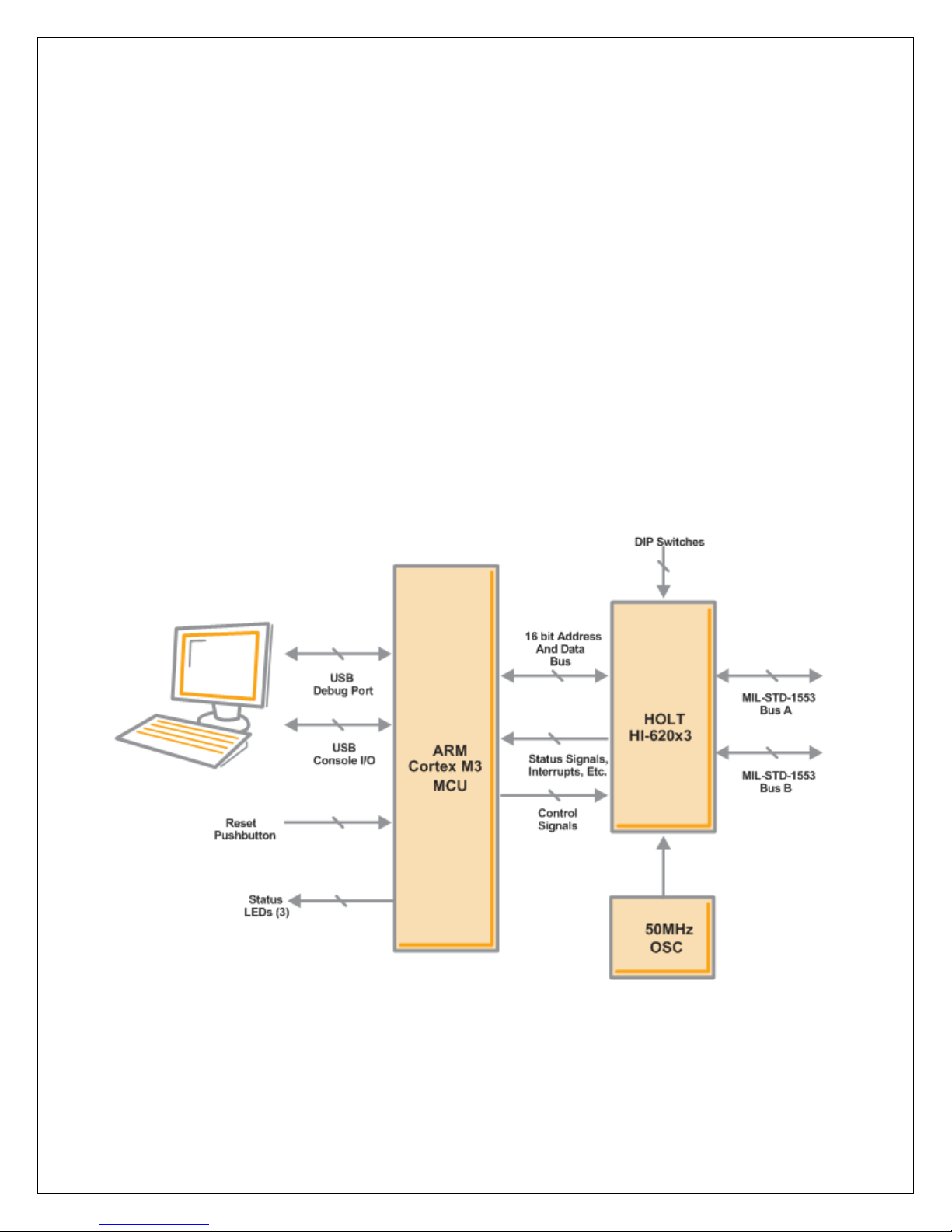
620x3 Host Interface
HI-620x3 features a 16 bit parallel data bus and has 64K x 16 word SRAM address space. It is offered in
an 80 pin QFP or QFN package.
The 620x3 has data transfer speeds that depend on which of the four available clock frequencies is
selected. The board is supplied with a 50MHz XTAL oscillator module, so by default the software will set
up 50MHz operation. However an external clock can be input through SMA connector J4, if this is done
jumper J7 should be connected. The device will run on a 50, 40, 20 or 16MHz clock, but the appropriate
register setting must be sent to register 0x18.
Control Switches
SW2 has six control functions that affect operation of the HI-620x3, these are explained in the
configuration section, please check they are in the default position before continuing.
RT address set up
The RT terminal address is set using DIP switches, before applying power. RT addresses 3 and 4
are utilized by the preprogrammed Bus Controller message repertoire. The 6-position DIP switch
SW1 should already be set with the address value 03, plus odd parity.
1760 Mode (all devices)
In this mode, the RT device responds with the Status Word’s Busy bit set within 2ms of Master
Reset pin rising edge. To test this feature, the device can be powered up without the software
running (for example by using SW1 RESET switch to hold the MCU in reset). If the MSCLR switch
is toggled on the ADK (SW2/3) the device can quickly respond to a BC command with the ‘Busy’
bit set.
1553 Bus Interface
Note 1: Connecting Bus Negative to ground is strictly a bench test convenience feature. Most
performance characteristics of transmitted and received 1553 signals are specified using
differential line-to-line measurements at the bus stub, Bus Positive minus Bus Negative. This
corresponds to the red and black “BUS” test points adjacent to the transformers on the right
side of the upper circuit board. While two oscilloscope probes connected to red and black may
be used in conjunction with scope’s Ch1-Ch2 math function, a single probe connected to Bus
Positive provides the same signal display when Bus Negative is grounded. This frees up scope
probes for other purposes. The nINCMD (TP4) signal can be used to trigger the scope as shown
in magenta trace on plots from the next page, this signal goes low during 1553 activity.
Do not include a provision for grounding Bus Negative in your production design.
Note 2: For stand-alone testing (without connection to a conventional MIL-STD 1553 bus) the hardware
provides on-board 70Ω termination resistors. This is strictly a bench test convenience feature

Holt Integrated Circuits 10
that supports demonstration of BC and RT without external 1553 bus connections. When using
the RT/MT mode the RT can fully transact messages, with or without the bus monitor.
On-board termination resistors are not used when connecting to a properly terminated MIL-
STD-1553 bus. Do not include a provision for termination resistors in your production design.
BusA 1553 output and nINCMD signal, in BC mode generating bus command
BusA 1553 output and nINCMD signal, in RT mode, responding to TxData command

Holt Integrated Circuits 11
Initial Setting Up
The Holt 620x3 Application Development Kit is designed to support the HI-62003 and HI-62023
devices in the QFP 80 pin package. The HI-62003 is used as the example, this has 64K of 16 bit
SRAM and will operate in all three modes; Remote Terminal (RT), Bus Controller (BC), SMT Bus
Monitor (MT). The HI-62023 can also be fitted, this has RT only capability.
Windows 7, 10 …
Install the free open-source terminal emulation program, TeraTerm 4.71, by running the
provided teraterm-4.71.exe installer program from the Holt CD. Accept the license agreement
stating redistribution is permitted provided that copyright notice is retained. The notice can be
displayed from the TeraTerm window by clicking Help then clicking About TeraTerm. Continuing
to install…
Accept the default install destination and click Next.
At the Select Components screen, unselect all options except Additional Plugin =
TTXResizeMenu and click Next.
Select the installed language, then click Next.
Accept the default Start Menu folder, then click Next.
Select any desired shortcuts, then click Next.
At the Ready to Install screen, click Install.
Run the TeraTerm program. At the New Connection screen, select (x)Serial and choose the
selected COM port. Click Setup then Serial Port to open the serial port setup window. Choose
these settings: Baud Rate: 115200, Data: 8 bits, Parity: none, Stop: 1 bit, Flow Control: none.
The board can be powered from both a 5VDC bench power supply or the 5V USB supply, if using
the USB supply jumper J6 on the lower ARM board should be closed, note however that on
many PCs the USB does not have sufficient power to supply the board when it is transmitting. If
using the bench supply make sure J6 is open. If TeraTerm is running and configured correctly,
the command menu below should appear in the console window. This menu appears whenever
board power is applied, or the RESET pushbutton is pressed. After verifying correct TeraTerm
communication with the evaluation board, the terminal set up can be saved by clicking Setup
then Save Setup.

Holt Integrated Circuits 12
The RT terminal address is set using DIP switches SW1. RT address 3 is utilized by the preprogrammed
Bus Controller message repertoire. The 6-position DIP switch should already be set with the address
value 03, plus odd parity.
The dates and times shown will differ from the screen captures shown below.
Press ‘w’ to reset the HI-620x3, then press ‘d’ to display the HI-620x3 registers, display should look
similar to below:

Holt Integrated Circuits 13
Reg #5 data is the time tag counter and will continually change, Reg #9 is the RT address register and
content 0007 reflects RT address 3 is set. Reg #1C is the self test register and a800 reflects that the
protocol test was run on power up and passed. Note the RSBITEN pin has to be high for this test to run
on reset.
General Structure of Demo Functions
The Holt API demonstration program is run from the source files in the src (source) folder. The main.c
file calls the console.c and executes demo functions in bcdemo.c, bcAsyncDemo.c and rtmtdemo.c. The
Holt API runtime library is contained in the library HI-62xxx lib as executable object code. Files xdemo.c
contain the demo initialization API function calls supporting demonstrations executed from the console
menu to initialize the BC, RT and monitor terminals. Key presses are detected in console.c
Commands ‘a’ and ‘b’ transmit BC async commands onto the A and B bus respectively and can be
viewed on an oscilloscope. The ‘f’ command will transmit a Major/Minor frame. These demos
demonstrate how Holt API’s are used to generate BC Asynchronous messages, Major/Minor frames, low

Holt Integrated Circuits 14
priority and high priority messages. View these messages with external MIL-STD-1553 test equipment or
on an oscilloscope.
This exercise uses the internal BC to transmit messages, so message traffic data is displayed on the
console. If an external BC is already connected to the bus jack though a bus coupler, it is okay to leave it
connected, but disable any external BC transmissions that will conflict with the on-chip BC
transmissions. A snap shot of the output data is shown below:
BC Mode (using an external RT)
1. Commands ‘a’ and ‘b’ transmit BC async commands onto the A and B bus respectively and can
be viewed on an oscilloscope, as shown below. These are Receive data commands to an RT
address = ‘3’. A series of four RxData commands are sent with 1 to 4 data words.
2. Connect an RT to BUSA and set RT address to 3, monitor the Bus with a oscilloscope or monitor,
a a response similar to below should be seen, with the RT responding with a clear status word:
3. The ‘f’ command will transmit a Major/Minor frame. These demos demonstrate how Holt API’s
are used to generate BC Asynchronous messages, Major/Minor frames, low priority and high
priority messages. Below is a snap shot of the major frame sequence containing 4 minor frames,
this is continually repeated, the second snap shot shows the first minor frame:
The 0x1800 word is the RT address 3 responding with a clear status.

Holt Integrated Circuits 15
4. The message data for the Major/Minor frames is contained in the bcdemo.c program and can
easily edited. As shipped RT address 3 is used.
RT Mode, using an external BC
Use an external BC tester (such as Ballard USB 1553) to transmit messages to the demo
board.
1. When an external BC is connected using conventional 1553 buses, use cables to connect the
demo board circular tri-axial bus jacks to bus coupler ports on the A and B bus networks. In this
case, the on-board dummy bus load 70Ω resistors should be disconnected. If bus couplers are
not readily available, bench testing can be done by enabling the on-board dummy bus load 70 Ω
resistors (R4, 5) and connecting BC tester cables directly to the demo board tri-axial jacks for
buses A and B.
2. Press ‘w’ command to reset device, then ‘r’ to set RT mode. This configures the HI-620x3 into an
RT terminal, with the address set on DIP switch SW1. The screen below will be displayed.
3. RT is set to single buffered mode. This RT set up supports data write and read from RT Sub-
address 1 and most mode codes, please refer to Holts API software manual for more details.

Holt Integrated Circuits 16
4. As in example before, use 1553 tester to a 03-T-01-02 Xmt command (0x1822). The Bus data
should look similar to below.
Response to receive two data words to SA1
Response to Transmit two words from SA1

Holt Integrated Circuits 17
RT/MT Mode, using an external BC
Use an external BC tester (such as Ballard USB 1553) to transmit messages to the demo
board.
1. Press ‘w’ command to reset device, then ‘c’ to set RT/MT mode. This configures the device into
an RT terminal and a Monitor. The screen below will be displayed:
2. RT is set to single buffered mode. The RT is set up as in RT mode above, but additionally it will
monitor traffic on the bus and report the data log to the terminal screen. Send a 03-T-01-02
command from the 1553 tester, then send a 03-R-01-02 command. The screen will show a data
log similar to below:

Holt Integrated Circuits 18
1st line shows the MSG#, the time stamp, BUS being used, type of message
2nd line shows the command hex code and the subtext abbreviation for the command
3rd line shows the data content of the command in the format:
RT ADD - Tx/Rx Type –Subaddress - Word length
3. Send a Mode code 18 (Transmit last command), the command 03-R-01-02 sent above should be
logged as below, note only the hex content (0x1C22) of the message is displayed:
MT Mode, using an external BC
Use an external BC tester (such as Ballard USB 1553) to transmit messages to the demo
board.
1. The monitor mode is very similar to RT/MT mode but the RT is not enabled, the monitor
functions the same as in RT/MT section above.
2. Press ‘w’ command to reset device, then ‘t’ to set MT mode. This configures the device into a
Monitor only. The screen below will be displayed, additionally if a 03-T-01-02 command is sent a
log and response will be shown, with no response this time as the RT is disabled:

Holt Integrated Circuits 19

Holt Integrated Circuits 20
Getting Started with the Holt API demo software project and installing
IAR Systems Embedded Workbench for ARM Compiler
Getting Started with the Holt API demo software project and installing IAR Systems Embedded
Workbench for ARM Compiler
Installed IAR Systems Embedded Workbench for ARM (EWARM ) compiler is required BEFORE
adding the Holt demo projects so all Atmel board library files and the demo project folder are
created in the proper location. Follow the “Holt HI-620x3 API Demo Project Installation Guide”
found in the Project folder on the Holt USB DRIVE. Before proceeding to the next steps IAR must
be installed and the two Holt project folders must be in the proper folder locations, according to
that guide. Instructions beyond this point assume you have completed the above installation
tasks.
Launch IAR Embedded Workbench from the Windows Start menu. A blank screen should appear.
Open the Holt HI-620x3 API Demo Project from the IAR File pull-down menu, click on
File/Open/Workspace and navigate to the project folder location and select “HI-62xx.eww” and
click the Open button.
An IAR Workspace window should appear on the left side as shown below. If the Workspace
directory pane is missing, select “Workspace” from the View pull-down menu. Make any
window adjustments or open any of the folder groups to view included files to suit your
preferences.
Double click the main.c file, it should appear in the text editor pane, similar to the screen
capture below.
The first time a project is unzipped and installed in the appropriated folder a Rebuild All should
be performed (from Project pull down menu).
IAR getting started, project management and other guides are available from the IAR
Workbench Help pull down menu.
Table of contents
Other HOLT Motherboard manuals
Popular Motherboard manuals by other brands

Foxconn
Foxconn 661FX4MR-ES Layout Easy installation guide

MSI
MSI IMGS45-M user manual

VIA Mainboard
VIA Mainboard EPIA Mini-ITX Operation guideline

NXP Semiconductors
NXP Semiconductors i.MX 8QuadXPlus Hardware user's guide

ATX
ATX IMBA-Q870-i2 Quick installation guide

Inrevium
Inrevium TB-FMCH-DP3 Hardware user manual