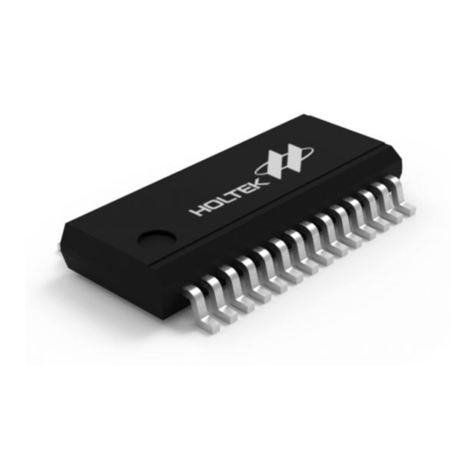
Holtek BS83A04C User manual

4-Key Enhanced Touch I/O Flash MCU
BS83A04C
Revision: V1.00 Date: March 24, 2020

Rev. 1.00 2 March 24, 2020 Rev. 1.00 3 March 24, 2020
BS83A04C
4-Key Enhanced Touch I/O Flash MCU
BS83A04C
4-Key Enhanced Touch I/O Flash MCU
Table of Contents
Features................................................................................................................. 6
CPU Features ...............................................................................................................................6
Peripheral Features.......................................................................................................................6
General Description.............................................................................................. 7
Block Diagram....................................................................................................... 7
Pin Assignment..................................................................................................... 8
Pin Descriptions ................................................................................................... 8
Absolute Maximum Ratings............................................................................... 10
D.C. Characteristics............................................................................................ 10
Operating Voltage Characteristics...............................................................................................10
Standby Current Characteristics .................................................................................................10
Operating Current Characteristics............................................................................................... 11
A.C. Characteristics............................................................................................ 11
High Speed Internal Oscillator – HIRC – Frequency Accuracy ................................................... 11
Low Speed Internal Oscillator Characteristics – LIRC ................................................................ 11
Operating Frequency Characteristic Curves ...............................................................................12
System Start Up Time Characteristics ........................................................................................12
Input/Output Characteristics ............................................................................. 13
Memory Characteristics ..................................................................................... 13
LVR Electrical Characteristics........................................................................... 14
Power-on Reset Characteristics........................................................................ 14
System Architecture........................................................................................... 14
Clocking and Pipelining...............................................................................................................14
Program Counter.........................................................................................................................15
Stack ...........................................................................................................................................16
Arithmetic and Logic Unit – ALU .................................................................................................16
Flash Program Memory...................................................................................... 17
Structure......................................................................................................................................17
Special Vectors ...........................................................................................................................17
Look-up Table..............................................................................................................................17
Table Program Example..............................................................................................................18
In Circuit Programming – ICP .....................................................................................................18
On-Chip Debug Support – OCDS ...............................................................................................19
Data Memory ....................................................................................................... 20
Structure......................................................................................................................................20
General Purpose Data Memory ..................................................................................................20
Special Purpose Data Memory ...................................................................................................21
Special Function Register Description............................................................. 22
Indirect Addressing Registers – IAR0, IAR1 ...............................................................................22

Rev. 1.00 2 March 24, 2020 Rev. 1.00 3 March 24, 2020
BS83A04C
4-Key Enhanced Touch I/O Flash MCU
BS83A04C
4-Key Enhanced Touch I/O Flash MCU
Memory Pointers – MP0, MP1 ....................................................................................................22
Bank Pointer – BP.......................................................................................................................23
Accumulator – ACC.....................................................................................................................23
Program Counter Low Register – PCL........................................................................................23
Look-up Table Registers – TBLP, TBHP, TBLH...........................................................................23
Status Register – STATUS..........................................................................................................24
Emulated EEPROM Data Memory ..................................................................... 25
Emulated EEPROM Data Memory Structure ..............................................................................25
Emulated EEPROM Registers ....................................................................................................26
Erasing the Emulated EEPROM .................................................................................................29
Writing Data to the Emulated EEPROM......................................................................................29
Reading Data from the Emulated EEPROM ...............................................................................29
Programming Considerations......................................................................................................30
Oscillators ........................................................................................................... 31
Oscillator Overview .....................................................................................................................31
System Clock Congurations......................................................................................................31
Internal High Speed RC Oscillator – HIRC .................................................................................32
Internal 32kHz Oscillator – LIRC.................................................................................................32
Operating Modes and System Clocks .............................................................. 32
System Clocks ............................................................................................................................32
System Operation Modes............................................................................................................33
Control Registers ........................................................................................................................34
Operating Mode Switching ..........................................................................................................36
Standby Current Considerations .................................................................................................39
Wake-up......................................................................................................................................39
Watchdog Timer.................................................................................................. 40
Watchdog Timer Clock Source....................................................................................................40
Watchdog Timer Control Register ...............................................................................................40
Watchdog Timer Operation .........................................................................................................41
Reset and Initialisation....................................................................................... 42
Reset Functions ..........................................................................................................................42
Reset Initial Conditions ...............................................................................................................44
Input/Output Ports .............................................................................................. 47
Pull-high Resistors ......................................................................................................................47
Port A Wake-up ...........................................................................................................................48
I/O Port Control Registers ...........................................................................................................48
Pin-shared Functions ..................................................................................................................49
I/O Pin Structures........................................................................................................................51
Programming Considerations......................................................................................................51
Timer Module – TM ............................................................................................. 52
Introduction .................................................................................................................................52
TM Operation ..............................................................................................................................52
TM Clock Source.........................................................................................................................52
TM Interrupts...............................................................................................................................52

Rev. 1.00 4 March 24, 2020 Rev. 1.00 5 March 24, 2020
BS83A04C
4-Key Enhanced Touch I/O Flash MCU
BS83A04C
4-Key Enhanced Touch I/O Flash MCU
TM External Pins.........................................................................................................................52
Programming Considerations......................................................................................................53
Compact Type TM – CTM ................................................................................... 54
Compact TM Operation...............................................................................................................54
Compact Type TM Register Description......................................................................................54
Compact Type TM Operating Modes ..........................................................................................58
Touch Key Function ........................................................................................... 64
Touch Key Structure....................................................................................................................64
Touch Key Register Denition.....................................................................................................64
Touch Key Operation...................................................................................................................73
Touch Key Data Memory.............................................................................................................76
Touch Key Scan Operation Flowchart.........................................................................................77
Touch Key Interrupts ...................................................................................................................79
Programming Considerations......................................................................................................79
I2C Interface ......................................................................................................... 80
I2C Interface Operation................................................................................................................80
I2C Registers ...............................................................................................................................81
I2C Bus Communication ..............................................................................................................84
I2C Time-out Control....................................................................................................................87
Interrupts ............................................................................................................. 89
Interrupt Registers.......................................................................................................................89
Interrupt Operation ......................................................................................................................92
External Interrupt.........................................................................................................................93
I2C Interrupt .................................................................................................................................93
Time Base Interrupt.....................................................................................................................93
Multi-function Interrupt ................................................................................................................94
Touch Key TKRCOV Interrupt .....................................................................................................95
Touch Key Threshold TKTH Interrupt..........................................................................................95
TM Interrupt.................................................................................................................................95
Interrupt Wake-up Function.........................................................................................................96
Programming Considerations......................................................................................................96
Application Circuits............................................................................................ 97
Instruction Set..................................................................................................... 98
Introduction .................................................................................................................................98
Instruction Timing ........................................................................................................................98
Moving and Transferring Data.....................................................................................................98
Arithmetic Operations..................................................................................................................98
Logical and Rotate Operation .....................................................................................................99
Branches and Control Transfer ...................................................................................................99
Bit Operations .............................................................................................................................99
Table Read Operations ...............................................................................................................99
Other Operations.........................................................................................................................99
Instruction Set Summary ................................................................................. 100
Table Conventions.....................................................................................................................100

Rev. 1.00 4 March 24, 2020 Rev. 1.00 5 March 24, 2020
BS83A04C
4-Key Enhanced Touch I/O Flash MCU
BS83A04C
4-Key Enhanced Touch I/O Flash MCU
Instruction Denition........................................................................................ 102
Package Information ........................................................................................ 111
8-pin SOP (150mil) Outline Dimensions ................................................................................... 112
10-pin DFN (3mm×3mm×0.75mm) Outline Dimensions ........................................................... 113
10-pin MSOP (118mil) Outline Dimensions............................................................................... 114
16-pin NSOP (150mil) Outline Dimensions............................................................................... 115

Rev. 1.00 6 March 24, 2020 Rev. 1.00 7 March 24, 2020
BS83A04C
4-Key Enhanced Touch I/O Flash MCU
BS83A04C
4-Key Enhanced Touch I/O Flash MCU
Features
CPU Features
• Operating Voltage
♦fSYS=8MHz: 1.8V~5.5V
• Up to 0.5μs instruction cycle with 8MHz system clock at VDD=5V
• Power down and wake-up functions to reduce power consumption
• Oscillator types
♦Internal High Speed 8MHz RC – HIRC
♦Internal Low Speed 32kHz RC – LIRC
• Multi-mode operation: FAST, SLOW, IDLE and SLEEP
• Fully integrated internal oscillators require no external components
• All instructions executed in one or two instruction cycles
• Table read instructions
• 63 powerful instructions
• 4-level subroutine nesting
• Bit manipulation instruction
Peripheral Features
• Flash Program Memory: 1K×16
• RAM Data Memory: 128×8
• Touch Key Data Memory: 24×8
• Emulated EEPROM Memory: 32×16
• Watchdog Timer function
• 8 bidirectional I/O lines
• Single external interrupt line shared with I/O pin
• Single 10-bit Compact Timer Module for time measure, compare match output, PWM output
function
• Single Time-Base function for generation of xed time interrupt signals
• I2C interface
• Low voltage reset function
• 4 touch key functions
• Package type: 8-pin SOP, 10-pin DFN/MSOP

Rev. 1.00 6 March 24, 2020 Rev. 1.00 7 March 24, 2020
BS83A04C
4-Key Enhanced Touch I/O Flash MCU
BS83A04C
4-Key Enhanced Touch I/O Flash MCU
General Description
The device is a Flash Memory type 8-bit high performance RISC architecture microcontroller with
fully integrated touch key functions.
With all touch key functions provided internally, this device range has all the features to
offer designers a reliable and easy means of implementing Touch Keyes within their products
applications. The touch key functions are fully integrated completely eliminating the need for
external components.
For memory features, the Flash Memory offers users the convenience of multi-programming
features. Other memory includes an area of RAM Data Memory as well as an area of Emulated
EEPROM memory for storage of non-volatile data such as serial numbers, calibration data etc.
Protective features such as an internal Watchdog Timer and Low Voltage Reset functions coupled
with excellent noise immunity and ESD protection ensure that reliable operation is maintained in
hostile electrical environments.
This device includes fully integrated low and high speed oscillators which require no external
components for their implementation. The ability to operate and switch dynamically between a range
of operating modes using dierent clock sources gives users the ability to optimise microcontroller
operation and minimise power consumption. Easy communication with the outside world is provided
using the internal I2C interface, while the inclusion of exible I/O programming features, Time-Base
function, Timer Module and many other features further enhance device functionality and exibility.
The touch key device will find excellent use in a huge range of modern Touch Key product
applications such as low power consumption portable devices, household appliances, consumer
products, etc.
Block Diagram
Interrupt
Controller
Bus
MUX
Reset
Circuit
Stack
4-Level
RAM
128 × 8
ROM
1K × 16
Watchdog
Timer
HIRC
8MHz
LIRC
32kHz
HT8 MCU Core
Time Base
Pin-Shared
with Port A
Emulated
EEPROM
32 × 16
LVR
Port A
Driver
Pin-Shared
Function PA0~PA7
Timer
I/O
I2C
INT
C to F
Circuit
Touch Key Module 0
MUX
Pin-Shared
with Port A
KEY1~KEY4
: Pin-Shared Node : Bus Entry
Clock System
Digital Peripherals
Touch Key Function

Rev. 1.00 8 March 24, 2020 Rev. 1.00 9 March 24, 2020
BS83A04C
4-Key Enhanced Touch I/O Flash MCU
BS83A04C
4-Key Enhanced Touch I/O Flash MCU
Pin Assignment
PA5/KEY1 VDD
PA1/KEY2
PA3/KEY3 PA2/CTPB/SDA/ICPCK
PA0/CTCK/INT/SCL/ICPDA
VSS
PA4/KEY4
BS83A04C
8 SOP-A
1
2
3
4
8
7
6
5
VDD
PA2/CTPB/SDA/ICPCK
BS83A04C
10 DFN-A/MSOP-A
10
9
8
7
6
1
2
3
4
5
PA4/KEY4
PA5/KEY1
PA3/KEY3
PA1/KEY2 PA0/CTCK/INT/SCL/ICPDA
VSS
PA6/CTCK/INT
PA7/CTP
NC
PA6/CTCK/INT
BS83AV04C
16 NSOP-A
16
15
14
13
12
11
10
9
1
2
3
4
5
6
7
8
VDD
PA5/KEY1
PA1/KEY2
PA3/KEY3
PA4/KEY4
OCDSCK
NC
PA0/CTCK/INT/SCL/ICPDA
PA2/CTPB/SDA/ICPCK
PA7/CTP
OCDSDA
NC
NC
VSS
Note: 1. If the pin-shared pin functions have multiple outputs simultaneously, the desired pin-shared
function is determined by the corresponding software control bits.
2. The 16-pin NSOP package type is only for OCDS EV chips. The OCDSDA and OCDSCK
pins are the OCDS dedicated pins.
3. For less pin-count package types there will be unbonded pins which should be properly
congured to avoid unwanted current consumption resulting from oating input conditions.
Refer to the “Standby Current Considerations” and “Input/Output Ports” sections.
Pin Descriptions
With the exception of the power pins, all pins on the device can be referenced by their Port name, e.g.
PA0, PA1 etc., which refer to the digital I/O function of the pins. However, these Port pins are also
shared with other function such as the Touch Key function, Timer Module pins etc. The function of
each pin is listed in the following table, however the details behind how each pin is congured is
contained in other sections of the datasheet.
As the Pin Description table shows the situation for the package with the most pins, not all pins in
the table will be available on smaller package sizes.

Rev. 1.00 8 March 24, 2020 Rev. 1.00 9 March 24, 2020
BS83A04C
4-Key Enhanced Touch I/O Flash MCU
BS83A04C
4-Key Enhanced Touch I/O Flash MCU
Pin Name Function OPT I/T O/T Description
PA0/CTCK/INT/SCL/
ICPDA
PA0
PAPU
PAWU
PAS0
ST CMOS General purpose I/O. Register enabled pull-up and
wake-up
CTCK PAS0
IFS ST — CTM clock input
INT
PAS0
IFS
INTEG
INTC0
ST — External Interrupt input
SCL PAS0 ST NMOS I2C clock line
ICPDA — ST CMOS ICP address/data
PA1/KEY2 PA1
PAPU
PAWU
PAS0
ST CMOS General purpose I/O. Register enabled pull-up and
wake-up
KEY2 PAS0 AN — Touch key input
PA2/CTPB/SDA/
ICPCK
PA2
PAPU
PAWU
PAS0
ST CMOS General purpose I/O. Register enabled pull-up and
wake-up
CTPB PAS0 — CMOS CTM inverted output
SDA PAS0 ST NMOS I2C data line
ICPCK — ST — ICP clock pin
PA3/KEY3 PA3
PAPU
PAWU
PAS0
ST CMOS General purpose I/O. Register enabled pull-up and
wake-up
KEY3 PAS0 AN — Touch key input
PA4/KEY4 PA4
PAPU
PAWU
PAS1
ST CMOS General purpose I/O. Register enabled pull-up and
wake-up
KEY4 PAS1 AN — Touch key input
PA5/KEY1 PA5
PAPU
PAWU
PAS1
ST CMOS General purpose I/O. Register enabled pull-up and
wake-up
KEY1 PAS1 AN — Touch key input
PA6/CTCK/INT
PA6 PAPU
PAWU ST CMOS General purpose I/O. Register enabled pull-up and
wake-up
CTCK IFS ST — CTM clock input
INT
IFS
INTEG
INTC0
ST — External Interrupt input
PA7/CTP PA7
PAPU
PAWU
PAS1
ST CMOS General purpose I/O. Register enabled pull-up and
wake-up
CTP PAS1 — CMOS CTM output
VDD VDD — PWR — Power supply
VSS VSS — PWR — Ground
For 16-pin NSOP package type only
OCDSDA OCDSDA — ST CMOS OCDS address/data pin, for EV chip only
OCDSCK OCDSCK — ST — OCDS clock pin, for EV chip only
Legend: I/T: Input type; O/T: Output type;
OPT: Optional by register option; PWR: Power;
ST: Schmitt Trigger input; CMOS: CMOS output;
NMOS: NMOS output; AN: Analog signal.

Rev. 1.00 10 March 24, 2020 Rev. 1.00 11 March 24, 2020
BS83A04C
4-Key Enhanced Touch I/O Flash MCU
BS83A04C
4-Key Enhanced Touch I/O Flash MCU
Absolute Maximum Ratings
Supply Voltage ..........................................................................................................VSS−0.3V to 6.0V
Input Voltage .................................................................................................... VSS−0.3V to VDD+0.3V
Storage Temperature..................................................................................................... -50°C to 125°C
Operating Temperature................................................................................................... -40°C to 85°C
IOH Total...................................................................................................................................... -80mA
IOL Total ....................................................................................................................................... 80mA
Total Power Dissipation ........................................................................................................... 500mW
Note: These are stress ratings only. Stresses exceeding the range specified under “Absolute
Maximum Ratings” may cause substantial damage to the device. Functional operation of the
device at other conditions beyond those listed in the specication is not implied and prolonged
exposure to extreme conditions may aect device reliability.
D.C. Characteristics
For data in the following tables, note that factors such as oscillator type, operating voltage, operating
frequency, pin load conditions, temperature and program instruction type, etc., can all exert an
inuence on the measured values.
Operating Voltage Characteristics
Ta=-40°C~85°C
Symbol Parameter Test Conditions Min. Typ. Max. Unit
VDD
Operating Voltage – HIRC fSYS=fHIRC=8MHz 1.8 — 5.5 V
Operating Voltage – LIRC fSYS=fLIRC=32kHz 1.8 — 5.5 V
Standby Current Characteristics
Ta=25°C
Symbol Standby Mode Test Conditions Min. Typ. Max. Max.
@85°C Unit
VDD Conditions
ISTB
SLEEP Mode
1.8V
WDT on
— 1.1 2.2 2.7
μA
3V — 1.5 3.0 3.6
5V — 3 5 6
IDLE0 Mode – LIRC
1.8V
fSUB on
— 2.4 4.0 4.8
μA3V — 3 5 6
5V — 5 10 12
IDLE1 Mode – HIRC
1.8V
fSUB on, fSYS=8MHz
— 288 400 480
μA3V — 360 500 600
5V — 600 800 960
Note: When using the characteristic table data, the following notes should be taken into consideration:
1. Any digital inputs are setup in a non-oating condition.
2. All measurements are taken under conditions of no load and with all peripherals in an o state.
3. There are no DC current paths.
4. All Standby Current values are taken after a HALT instruction execution thus stopping all instruction
execution.

Rev. 1.00 10 March 24, 2020 Rev. 1.00 11 March 24, 2020
BS83A04C
4-Key Enhanced Touch I/O Flash MCU
BS83A04C
4-Key Enhanced Touch I/O Flash MCU
Operating Current Characteristics
Ta=-40°C~85°C
Symbol Operating Mode Test Conditions Min. Typ. Max. Unit
VDD Conditions
IDD
SLOW Mode – LIRC
1.8V
fSYS=32kHz
— 7.5 15.0
μA3V — 10 20
5V — 30 50
FAST Mode – HIRC
1.8V
fSYS=8MHz
— 0.6 1.0
mA
3V — 0.8 1.2
5V — 1.6 2.4
Note: When using the characteristic table data, the following notes should be taken into consideration:
1. Any digital inputs are setup in a non-oating condition.
2. All measurements are taken under conditions of no load and with all peripherals in an o state.
3. There are no DC current paths.
4. All Operating Current values are measured using a continuous NOP instruction program loop.
A.C. Characteristics
For data in the following tables, note that factors such as oscillator type, operating voltage, operating
frequency and temperature etc., can all exert an inuence on the measured values.
High Speed Internal Oscillator – HIRC – Frequency Accuracy
During the program writing operation the writer will trim the HIRC oscillator at a user selected
HIRC frequency and user selected voltage of either 3V or 5V.
Symbol Parameter Test Conditions Min. Typ. Max. Unit
VDD Temp.
fHIRC 8MHz Writer Trimmed HIRC Frequency
3V/5V 25°C -1% 8 +1%
MHz
-40°C~85°C -2% 8 +2%
2.2V~5.5V 25°C -2.5% 8 +2.5%
-40°C~85°C -3% 8 +3%
1.8V~5.5V 25°C -5% 8 +3%
-40°C~85°C -10% 8 +5%
Note: 1. The 3V/5V values for VDD are provided as these are the two selectable xed voltages at which the HIRC
frequency is trimmed by the writer.
2. The row below the 3V/5V trim voltage row is provided to show the values for the full VDD range operating
voltage. It is recommended that the trim voltage is xed at 3V for application voltage ranges from 1.8V
to 3.6V and xed at 5V for application voltage ranges from 3.3V to 5.5V.
Low Speed Internal Oscillator Characteristics – LIRC
Symbol Parameter Test Conditions Min. Typ. Max. Unit
VDD Temp.
fLIRC LIRC Frequency 1.8V~5.5V -40°C~85°C -12% 32 +12% kHz
tSTART LIRC Start Up Time — -40°C~85°C — — 100 μs

Rev. 1.00 12 March 24, 2020 Rev. 1.00 13 March 24, 2020
BS83A04C
4-Key Enhanced Touch I/O Flash MCU
BS83A04C
4-Key Enhanced Touch I/O Flash MCU
Operating Frequency Characteristic Curves
System Operating Frequency
Operating Voltage
8MHz
1.8V
~
~
5.5V
~
~
~
~
System Start Up Time Characteristics
Ta=-40°C~85°C
Symbol Parameter Test Conditions Min. Typ. Max. Unit
VDD Conditions
tSST
System Start-up Time
Wake-up from condition where fSYS is o
— fSYS=fH~fH/64, fH=fHIRC — 16 — tHIRC
— fSYS=fSUB=fLIRC — 2 — tLIRC
System Start-up Time
Wake-up from condition where fSYS is on
— fSYS=fH~fH/64, fH=fHIRC — 2 — tH
— fSYS=fSUB=fLIRC — 2 — tSUB
System Speed Switch Time
FAST to SLOW Mode or
SLOW to FAST Mode
— fHIRC switches from o → on — 16 — tHIRC
tRSTD
System Reset Delay Time
Reset source from Power-on reset or LVR
hardware reset
— RRPOR=5V/ms
42 48 54 ms
System Reset Delay Time
WDTC/RSTC software reset — —
System Reset Delay Time
Reset source from WDT overow — — 14 16 18 ms
tSRESET Minimum Software Reset Width to Reset — — 45 90 120 μs
Note: 1. For the System Start-up time values, whether fSYS is on or o depends upon the mode type and the chosen
fSYS system oscillator. Details are provided in the System Operating Modes section.
2. The time units, shown by the symbols tHIRC, tSYS etc. are the inverse of the corresponding frequency values
as provided in the frequency tables. For example: tHIRC=1/fHIRC, tSYS=1/fSYS etc.
3. If the LIRC is used as the system clock and if it is o when in the SLEEP Mode, then an additional LIRC
start up time, tSTART, as provided in the LIRC frequency table, must be added to the tSST time in the table
above.
4. The System Speed Switch Time is eectively the time taken for the newly activated oscillator to start up.

Rev. 1.00 12 March 24, 2020 Rev. 1.00 13 March 24, 2020
BS83A04C
4-Key Enhanced Touch I/O Flash MCU
BS83A04C
4-Key Enhanced Touch I/O Flash MCU
Input/Output Characteristics
Ta=-40°C~85°C
Symbol Parameter Test Conditions Min. Typ. Max. Unit
VDD Conditions
VIL Input Low Voltage for I/O Port or Input Pins 5V —0 — 1.5 V
— 0 — 0.2VDD
VIH Input High Voltage for I/O Port or Input Pins 5V —3.5 — 5.0 V
— 0.8VDD — VDD
IOL Sink Current for I/O Ports 3V VOL=0.1VDD
16 32 — mA
5V 32 65 —
IOH Source Current for I/O Ports 3V VOH=0.9VDD
-4 -8 — mA
5V -8 -16 —
RPH Pull-high Resistance for I/O Port(Note)
3V LVPU=0 20 60 100
kΩ
5V 10 30 50
3V LVPU=1 6.67 15.00 23.00
5V 3.5 7.5 12.0
ILEAK Input Leakage Current 5V VIN=VDD or VIN=VSS — — ±1 μA
tTCK TM TCK Input Pin Minimum Pulse Width — — 0.3 — — μs
tINT External Interrupt Minimum Pulse Width — — 10 — — μs
Note: The RPH internal pull high resistance value is calculated by connecting to ground and enabling the input pin
with a pull-high resistor and then measuring the pin current at the specied supply voltage level. Dividing
the voltage by this measured current provides the RPH value.
Memory Characteristics
Ta=-40°C~85°C, unless otherwise specied
Symbol Parameter Test Conditions Min. Typ. Max. Unit
VDD Conditions
Flash Program Memory / Emulated EEPROM Memory
VDD
Operating Voltage for Read — — 1.8 — 5.5
V
Operating Voltage for Erase/Write – Flash
Program Memory — — 3.0 — 5.5
Operating Voltage for Erase/Write –
Emulated EEPROM Memory — — 4.5 5.0 5.5
tDEW
Erase / Write Time – Flash Program Memory 5V Ta=25°C — 2 3 ms
Erase / Write Cycle Time – Emulated
EEPROM Memory
— EWRTS[1:0]=00B — 2 3
ms
— EWRTS[1:0]=01B — 4 6
— EWRTS[1:0]=10B — 8 12
— EWRTS[1:0]=11B — 16 24
IDDPGM Programming/Erase Current on VDD 5V — — — 5.0 mA
EPCell Endurance — — 10K — — E/W
tRETD ROM Data Retention Time — Ta=25°C — 40 — Year
RAM Data Memory
VDD Operating Voltage for Read/Write — — VDDmin — VDDmax V
VDR RAM Data Retention Voltage — Device in SLEEP Mode 1.0 — — V
Note: The Emulated EEPROM erase/write operation can only be executed when the fSYS clock frequency is equal
to or greater than 2MHz.

Rev. 1.00 14 March 24, 2020 Rev. 1.00 15 March 24, 2020
BS83A04C
4-Key Enhanced Touch I/O Flash MCU
BS83A04C
4-Key Enhanced Touch I/O Flash MCU
LVR Electrical Characteristics
Ta=25°C
Symbol Parameter Test Conditions Min. Typ. Max. Unit
VDD Conditions
VLVR Low Voltage Reset Voltage — LVR enable, voltage is 1.7V -5% 1.7 +5% V
ILVRBG Operating current 3V LVR enable, VLVR =1.7V — — 15 μA
5V — 15 25
tLVR Minimum Low Voltage Width to Reset — — 120 240 480 μs
Power-on Reset Characteristics
Ta=25°C
Symbol Parameter Test Conditions Min. Typ. Max. Unit
VDD Conditions
VPOR VDD Start Voltage to Ensure Power-on Reset — — — — 100 mV
RRPOR VDD Rising Rate to Ensure Power-on Reset — — 0.035 — — V/ms
tPOR
Minimum Time for VDD Stays at VPOR to Ensure
Power-on Reset — — 1 — — ms
VDD
tPOR RRPOR
VPOR
Time
System Architecture
A key factor in the high-performance features of the Holtek range of microcontrollers is attributed
to their internal system architecture. The device takes advantage of the usual features found within
RISC microcontrollers providing increased speed of operation and Periodic performance. The
pipelining scheme is implemented in such a way that instruction fetching and instruction execution
are overlapped, hence instructions are eectively executed in one cycle, with the exception of branch
or call instructions. An 8-bit wide ALU is used in practically all instruction set operations, which
carries out arithmetic operations, logic operations, rotation, increment, decrement, branch decisions,
etc. The internal data path is simplified by moving data through the Accumulator and the ALU.
Certain internal registers are implemented in the Data Memory and can be directly or indirectly
addressed. The simple addressing methods of these registers along with additional architectural
features ensure that a minimum of external components is required to provide a functional I/O
control system with maximum reliability and exibility. This makes the device suitable for low-cost,
high-volume production for controller applications.
Clocking and Pipelining
The main system clock, derived from either an HIRC or LIRC oscillator is subdivided into four
internally generated non-overlapping clocks, T1~T4. The Program Counter is incremented at the
beginning of the T1 clock during which time a new instruction is fetched. The remaining T2~T4
clocks carry out the decoding and execution functions. In this way, one T1~T4 clock cycle forms

Rev. 1.00 14 March 24, 2020 Rev. 1.00 15 March 24, 2020
BS83A04C
4-Key Enhanced Touch I/O Flash MCU
BS83A04C
4-Key Enhanced Touch I/O Flash MCU
one instruction cycle. Although the fetching and execution of instructions takes place in consecutive
instruction cycles, the pipelining structure of the microcontroller ensures that instructions are
effectively executed in one instruction cycle. The exception to this are instructions where the
contents of the Program Counter are changed, such as subroutine calls or jumps, in which case the
instruction will take one more instruction cycle to execute.
For instructions involving branches, such as jump or call instructions, two machine cycles are required to
complete instruction execution. An extra cycle is required as the program takes one cycle to rst obtain
the actual jump or call address and then another cycle to actually execute the branch. The requirement
for this extra cycle should be taken into account by programmers in timing sensitive applications.
Fetch Inst. (PC)
(System Clock)
fSYS
Phase Clock T1
Phase Clock T2
Phase Clock T3
Phase Clock T4
Program Counter PC PC+1 PC+2
Pipelining Execute Inst. (PC-1) Fetch Inst. (PC+1)
Execute Inst. (PC) Fetch Inst. (PC+2)
Execute Inst. (PC+1)
System Clocking and Pipelining
Fetch Inst. 1
1 MOV A,[12H]
2 CALL DELAY
3 CPL [12H]
4 :
5 :
6 DELAY: NOP
Execute Inst. 1
Fetch Inst. 2 Execute Inst. 2
Fetch Inst. 3 Flush Pipeline
Fetch Inst. 6 Execute Inst. 6
Fetch Inst. 7
Instruction Fetching
Program Counter
During program execution, the Program Counter is used to keep track of the address of the
next instruction to be executed. It is automatically incremented by one each time an instruction
is executed except for instructions, such as “JMP” or “CALL” that demand a jump to a non-
consecutive Program Memory address. Only the lower 8 bits, known as the Program Counter Low
Register, are directly addressable by the application program.
When executing instructions requiring jumps to non-consecutive addresses such as a jump instruction,
a subroutine call, interrupt or reset, etc., the microcontroller manages program control by loading
the required address into the Program Counter. For conditional skip instructions, once the condition
has been met, the next instruction, which has already been fetched during the present instruction
execution, is discarded and a dummy cycle takes its place while the correct instruction is obtained.
Program Counter
Program Counter High Byte PCL Register
PC9~PC8 PCL7~PCL0
Program Counter

Rev. 1.00 16 March 24, 2020 Rev. 1.00 17 March 24, 2020
BS83A04C
4-Key Enhanced Touch I/O Flash MCU
BS83A04C
4-Key Enhanced Touch I/O Flash MCU
The lower byte of the Program Counter, known as the Program Counter Low register or PCL, is
available for program control and is a readable and writeable register. By transferring data directly
into this register, a short program jump can be executed directly; however, as only this low byte
is available for manipulation, the jumps are limited to the present page of memory that is 256
locations. When such program jumps are executed it should also be noted that a dummy cycle
will be inserted. Manipulating the PCL register may cause program branching, so an extra cycle is
needed to pre-fetch.
Stack
This is a special part of the memory which is used to save the contents of the Program Counter
only. The stack is organized into 4 levels and neither part of the data nor part of the program space,
and is neither readable nor writeable. The activated level is indexed by the Stack Pointer, and is
neither readable nor writeable. At a subroutine call or interrupt acknowledge signal, the contents of
the Program Counter are pushed onto the stack. At the end of a subroutine or an interrupt routine,
signaled by a return instruction, RET or RETI, the Program Counter is restored to its previous value
from the stack. After a device reset, the Stack Pointer will point to the top of the stack.
If the stack is full and an enabled interrupt takes place, the interrupt request ag will be recorded but
the acknowledge signal will be inhibited. When the Stack Pointer is decremented, by RET or RETI,
the interrupt will be serviced. This feature prevents stack overow allowing the programmer to use
the structure more easily. However, when the stack is full, a CALL subroutine instruction can still
be executed which will result in a stack overow. Precautions should be taken to avoid such cases
which might cause unpredictable program branching.
If the stack is overow, the rst Program Counter save in the stack will be lost.
Stack Level 2
Stack Level 1
Stack Level 3
Program Memory
Program Counter
Top of Stack
Stack Level 4Bottom of Stack
Stack
Pointer
Arithmetic and Logic Unit – ALU
The arithmetic-logic unit or ALU is a critical area of the microcontroller that carries out arithmetic
and logic operations of the instruction set. Connected to the main microcontroller data bus, the ALU
receives related instruction codes and performs the required arithmetic or logical operations after
which the result will be placed in the specied register. As these ALU calculation or operations may
result in carry, borrow or other status changes, the status register will be correspondingly updated to
reect these changes. The ALU supports the following functions:
• Arithmetic operations:
ADD, ADDM, ADC, ADCM, SUB, SUBM, SBC, SBCM, DAA
• Logic operations:
AND, OR, XOR, ANDM, ORM, XORM, CPL, CPLA
• Rotation:
RRA, RR, RRCA, RRC, RLA, RL, RLCA, RLC
• Increment and Decrement:
INCA, INC, DECA, DEC
• Branch decision:
JMP, SZ, SZA, SNZ, SIZ, SDZ, SIZA, SDZA, CALL, RET, RETI

Rev. 1.00 16 March 24, 2020 Rev. 1.00 17 March 24, 2020
BS83A04C
4-Key Enhanced Touch I/O Flash MCU
BS83A04C
4-Key Enhanced Touch I/O Flash MCU
Flash Program Memory
The Program Memory is the location where the user code or program is stored. For the device the
Program Memory is Flash type, which means it can be programmed and re-programmed a large
number of times, allowing the user the convenience of code modication on the same device. By
using the appropriate programming tools, the Flash device oers users the exibility to conveniently
debug and develop their applications while also oering a means of eld programming and updating.
Structure
The Program Memory has a capacity of 1K×16 bits. The Program Memory is addressed by the
Program Counter and also contains data, table information and interrupt entries. Table data, which can
be setup in any location within the Program Memory, is addressed by a separate table pointer register.
000H
004H
014H
3FFH
Reset
Interrupt
Vectors
16 bits
Program Memory Structure
Special Vectors
Within the Program Memory, certain locations are reserved for the reset and interrupts. The location
0000H is reserved for use by the device reset for program initialisation. After a device reset is
initiated, the program will jump to this location and begin execution.
Look-up Table
Any location within the Program Memory can be dened as a look-up table where programmers can
store xed data. To use the look-up table, the table pointer must rst be setup by placing the address
of the look up data to be retrieved in the table pointer register, TBLP and TBHP. These registers
dene the total address of the look-up table.
After setting up the table pointer, the table data can be retrieved from the Program Memory using
the “TABRD [m]” or “TABRDL [m]” instructions, respectively. When the instruction is executed,
the lower order table byte from the Program Memory will be transferred to the user defined
Data Memory register [m] as specified in the instruction. The higher order table data byte from
the Program Memory will be transferred to the TBLH special register. Any unused bits in this
transferred higher order byte will be read as “0”.
The accompanying diagram illustrates the addressing data ow of the look-up table.
Last Page or
TBHP Register
Address
TBLP Register
Data
16 bits
Program Memory
Register TBLH User Selected
Register
High Byte Low Byte

Rev. 1.00 18 March 24, 2020 Rev. 1.00 19 March 24, 2020
BS83A04C
4-Key Enhanced Touch I/O Flash MCU
BS83A04C
4-Key Enhanced Touch I/O Flash MCU
Table Program Example
The following example shows how the table pointer and table data is dened and retrieved from
the microcontroller. This example uses raw table data located in the Program Memory which is
stored there using the ORG statement. The value at this ORG statement is “0300H” which refers to
the start address of the last page within the 1K Program Memory of the microcontroller. The table
pointer low byte register is setup here to have an initial value of “06H”. This will ensure that the rst
data read from the data table will be at the Program Memory address “0306H” or 6 locations after
the start of the last page. Note that the value for the table pointer is referenced to the rst address
specied by TBLP and TBHP if the “TABRD [m]” instruction is being used. The high byte of the
table data which in this case is equal to zero will be transferred to the TBLH register automatically
when the “TABRD [m]” instruction is executed.
Because the TBLH register is a read-only register and cannot be restored, care should be taken
to ensure its protection if both the main routine and Interrupt Service Routine use table read
instructions. If using the table read instructions, the Interrupt Service Routines may change the
value of the TBLH and subsequently cause errors if used again by the main routine. As a rule, it is
recommended that simultaneous use of the table read instructions should be avoided. However, in
situations where simultaneous use cannot be avoided, the interrupts should be disabled prior to the
execution of any main routine table-read instructions. Note that all table related instructions require
two instruction cycles to complete their operation.
Table Read Program Example
tempreg1 db ? ; temporary register #1
tempreg2 db ? ; temporary register #2
:
:
mov a,06h ; initialise low table pointer - note that this address is referenced
mov tblp,a ; to the last page or the page that tbhp pointed
mov a,03h ; initialise high table pointer
mov tbhp,a
:
:
tabrd tempreg1 ; transfers value in table referenced by table pointer data at program
; memory address “0306H” transferred to tempreg1 and TBLH
dec tblp ; reduce value of table pointer by one
tabrd tempreg2 ; transfers value in table referenced by table pointer
; data at program memory address “0305H” transferred to tempreg2 and
; TBLH in this example the data “1AH” is transferred to tempreg1 and
; data “0FH” to register tempreg2
:
:
org 0300h ; sets initial address of program memory
dc 00Ah, 00Bh, 00Ch, 00Dh, 00Eh, 00Fh, 01Ah, 01Bh
In Circuit Programming – ICP
The provision of Flash type Program Memory provides the user with a means of convenient and
easy upgrades and modications to their programs on the same device.
As an additional convenience, Holtek has provided a means of programming the microcontroller in-
circuit using a 4-pin interface. This provides manufacturers with the possibility of manufacturing
their circuit boards complete with a programmed or un-programmed microcontroller, and then
programming or upgrading the program at a later stage. This enables product manufacturers to easily
keep their manufactured products supplied with the latest program releases without removal and re-
insertion of the device.

Rev. 1.00 18 March 24, 2020 Rev. 1.00 19 March 24, 2020
BS83A04C
4-Key Enhanced Touch I/O Flash MCU
BS83A04C
4-Key Enhanced Touch I/O Flash MCU
Holtek Writer Pins MCU Programming Pins Pin Description
ICPDA PA0 Programming Serial Data/Address
ICPCK PA2 Programming Clock
VDD VDD Power Supply
VSS VSS Ground
The Program Memory can be programmed serially in-circuit using this 4-wire interface. Data
is downloaded and uploaded serially on a single pin with an additional line for the clock.
Two additional lines are required for the power supply. The technical details regarding the in-
circuit programming of the device is beyond the scope of this document and will be supplied in
supplementary literature.
During the programming process, the user must take care of the ICPDA and ICPCK pins for data
and clock programming purposes to ensure that no other outputs are connected to these two pins.
* *
Writer_VDD
ICPDA
ICPCK
Writer_VSS
To other Circuit
VDD
PA0
PA2
VSS
Writer Connector
Signals
MCU Programming
Pins
Note: * may be resistor or capacitor. The resistance of * must be greater than 1kΩ or the capacitance
of * must be less than 1nF.
On-Chip Debug Support – OCDS
There is an EV chip named BS83AV04C which is used to emulate the BS83A04C device. The EV
chip device also provides an “On-Chip Debug” function to debug the real MCU device during the
development process. The EV chip and the real MCU device are almost functionally compatible
except for “On-Chip Debug” function and package type. Users can use the EV chip device to
emulate the real chip device behavior by connecting the OCDSDA and OCDSCK pins to the Holtek
HT-IDE development tools. The OCDSDA pin is the OCDS Data/Address input/output pin while
the OCDSCK pin is the OCDS clock input pin. For more detailed OCDS information, refer to the
corresponding document named “Holtek e-Link for 8-bit MCU OCDS User’s Guide”.
Holtek e-Link Pins EV Chip OCDS Pins Pin Description
OCDSDA OCDSDA On-Chip Debug Support Data/Address input/output
OCDSCK OCDSCK On-Chip Debug Support Clock input
VDD VDD Power Supply
VSS VSS Ground

Rev. 1.00 20 March 24, 2020 Rev. 1.00 21 March 24, 2020
BS83A04C
4-Key Enhanced Touch I/O Flash MCU
BS83A04C
4-Key Enhanced Touch I/O Flash MCU
Data Memory
The Data Memory is a volatile area of 8-bit wide RAM internal memory and is the location where
temporary information is stored.
Structure
Categorized into two types, the rst of these is an area of RAM, known as the Special Function Data
Memory. Here are located registers which are necessary for correct operation of the device. Many
of these registers can be read from and written to directly under program control, however, some
remain protected from user manipulation. The second area of Data Memory is known as the General
Purpose Data Memory, which is reserved for general purpose use. All locations within this area are
read and write accessible under program control. There is another area of Data Memory reserved for
the Touch Key Data Memory.
The overall Data Memory is subdivided into several banks. The Special Purpose Data Memory
registers are accessible in Bank 0. The Touch Key Data Memory is located in Bank 5~Bank 7.
Switching between the dierent Data Memory banks is achieved by setting the Bank Pointer to the
correct value. The start address of the Data Memory for the device is the address 00H.
Special Purpose Data Memory General Purpose Data Memory Touch Key Data Memory
Available Bank Capacity Bank Capacity Banks
0 128×8 Bank 0: 80H~FFH 24×8
Bank 5: 00H~07H
Bank 6: 00H~07H
Bank 7: 00H~07H
Data Memory Summary
00H
80H
FFH
Special Purpose
Data Memory
(Bank 0 )
General Purpose
Data Memory
(Bank 0)
7FH
Bank 0
Touch Key
Data Memory
(Bank 5 ~ Bank 7)
07H
40H
Data Memory Structure
General Purpose Data Memory
All microcontroller programs require an area of read/write memory where temporary data can be
stored and retrieved for use later. It is this area of RAM memory that is known as General Purpose
Data Memory. This area of Data Memory is fully accessible by the user programing for both reading
and writing operations. By using the bit operation instructions individual bits can be set or reset
under program control giving the user a large range of exibility for bit manipulation in the Data
Memory.
Table of contents
Other Holtek Microcontroller manuals

Holtek
Holtek HT66F03T3 User manual

Holtek
Holtek HT49RA0 User manual

Holtek
Holtek HT32 MCU User manual

Holtek
Holtek BS83B24C User manual

Holtek
Holtek HT66F488 User manual

Holtek
Holtek HT48RU80 User manual

Holtek
Holtek HT827A0 User manual

Holtek
Holtek HT46RU75D-1 User manual

Holtek
Holtek HT8 Easy DEV User manual

Holtek
Holtek HT32F52342 User manual

Holtek
Holtek HT32F12345 User manual

Holtek
Holtek HT46R46 User manual

Holtek
Holtek HT85F2270 User manual

Holtek
Holtek HT48RA1 User manual

Holtek
Holtek BC66F2332-1 User manual

Holtek
Holtek BS67F340 User manual

Holtek
Holtek HTG2190 User manual

Holtek
Holtek BS83B08-3 User manual

Holtek
Holtek HT16C22 Instructions for use

Holtek
Holtek HT49RU80 User manual