Holtek HT45R36 Reference manual
Other Holtek Microcontroller manuals
Holtek
Holtek HT85F2270 User manual
Holtek
Holtek HT32F52243 User manual
Holtek
Holtek HT32F52342 User manual
Holtek
Holtek HT46RU75D-1 User manual
Holtek
Holtek BS86DH12C User manual
Holtek
Holtek HT32 User manual
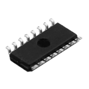
Holtek
Holtek HT45F23A User manual
Holtek
Holtek HT49R30A-1 User manual
Holtek
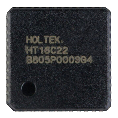
Holtek HT16C22 Instructions for use

Holtek
Holtek HT32F50231 User manual
Holtek
Holtek BS83A04C User manual

Holtek
Holtek BS83A02L User manual
Holtek
Holtek BC66F2332-1 User manual

Holtek
Holtek HT66F20 User manual
Holtek
Holtek HT49RU80 User manual
Holtek
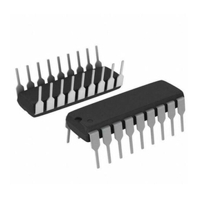
Holtek HT46R46 User manual

Holtek
Holtek HT32 Instruction Manual
Holtek
Holtek BS83B08-3 User manual
Holtek
Holtek HT66F60A User manual
Holtek
Holtek HT46R74D-1 Technical manual
Popular Microcontroller manuals by other brands

DIGITAL-LOGIC
DIGITAL-LOGIC MICROSPACE manual

Texas Instruments
Texas Instruments TMS320F2837 D Series Workshop Guide and Lab Manual

CYPRES
CYPRES CY14NVSRAMKIT-001 user guide

Espressif Systems
Espressif Systems ESP8266EX Programming guide

Abov
Abov AC33M8128L user manual
Silicon Laboratories
Silicon Laboratories C8051F800 user guide

