www.holzmann-maschinen.at
Dear Customer!
This manual contains Information and im-
portant instructions for the installation and
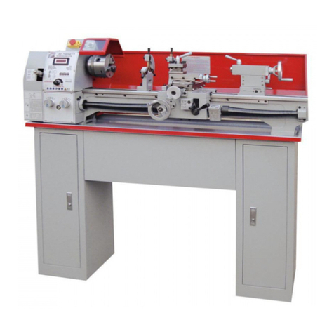
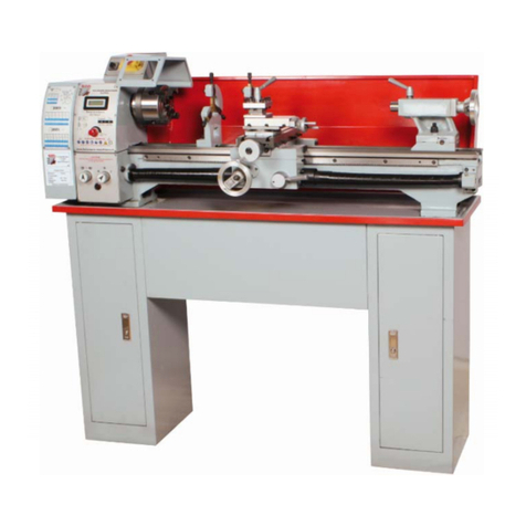
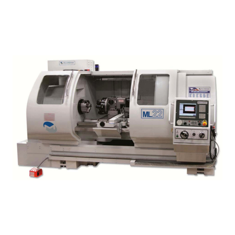
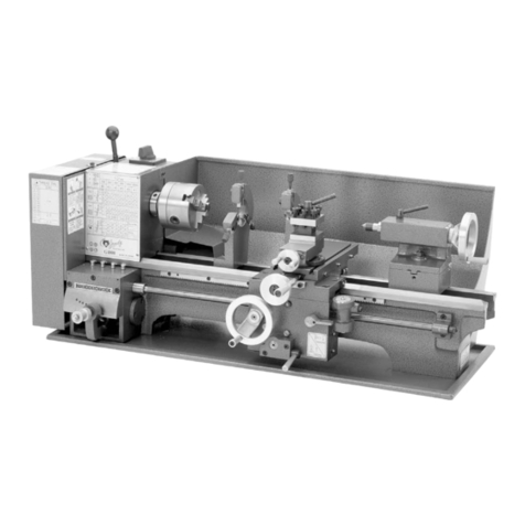
correct use of the metal lathe ED 400FD
This manual is part of the machine and
may not be stored separately from the
machine. Save it for later reference and
if you let other persons use the machine,
add this instruction to the ma-chine.
Please read and obey the security instruc-
tions!
Before rst use read this manual
carefully. It eases the correct use
of the machine and prevents misunder-
standing and damages of machine and the
user’s health.
Due to constant advancements in product
design and construction pictures and con-
tent may di-verse slightly. However, if you
discover any errors, inform us please with
the product feedback form.
Technical specications are subject to
changes!
Copyright © 2011
This document is protected by internati-
onal copyright law. Any unauthorized du-
plication, translation or use of pictures,
illustrations or text of this manual will be
pursued by law – court of jurisdiction is
A-4020 Linz, Austria!
Sehr geehrter Kunde!
Diese Bedienungsanleitung enthält Infor-
mationen und wichtige Hinweise zur Inbe-
triebnahme und Handhabung der Metall-
drehbank ED 400FD
Die Bedienungsanleitung ist Bestandteil
der Maschine und darf nicht entfernt wer-
den. Bewahren Sie sie für spätere Zwecke
auf und legen Sie diese Anleitung der Ma-
schine bei, wenn sie an Dritte weitergege-
ben wird!
Bitte beachten Sie die Sicherheits-
hinweise!
Lesen Sie vor Inbetriebnahme diese Anlei-
tung aufmerksam durch. Der sachgemäße
Umgang wird Ihnen dadurch erleichtert,
Missverständnissen und etwaigen Schä-
den wird vorgebeugt. Halten Sie sich an
die Warn- und Sicherheitshinweise. Miss-
achtung kann zu ernsten Verletzungen
führen.
Durch die ständige Weiterentwicklung un-
serer Produkte können Abbildungen und
Inhalte gering-fügig abweichen. Sollten
Sie jedoch Fehler feststellen, informieren
Sie uns bitte über E-Mail oder Fax mit Pro-
duktinformationsformular am Ende dieser
Anleitung.
Technische Änderungen und Irrtümer vor-
behalten!
Urheberrecht © 2011
Diese Dokumentation ist urheberrechtlich
geschützt. Die dadurch verfassungsmäßi-
gen Rechte bleiben vorbehalten! Insbe-
sondere der Nachdruck, die Übersetzung
und die Entnahme von Fotos und Abbil-
dungen werden gerichtlich verfolgt – Ge-
richtsstand ist A-4020 Linz, Austria!
ENGLISH DEUTSCH

