manuals.online logo
Brands
  1. Home
  2. •
  3. Brands
  4. •
  5. Home Styles
  6. •
  7. Indoor Furnishing
  8. •
  9. Home Styles 50 942 User manual

Home Styles 50 942 User manual

Part List
Home Styles Customer Service: www.homestylesfurniture.com,
[email protected], 888-680-7460, 877-831-0319
Tool(s) required for assembly: Phillips screwdriver, Level
N.
Middle Panel
1 pc.
Q.
Divider
1 pc.
T.
Door
1 pc.
U.
Door
1 pc.
X.
Shelf
3 pcs.
Z.
Drawer
2 pcs.
Y.
Shelf
2 pcs.
L.
Side Panel
1 pc.
M.
Side Panel
1 pc.
D.
Plinth
1 pc.
E.
Plinth
1 pc.
IMPORTANT
Carefully remove all the parts from the carton and
place them individually on a soft cloth to prevent
scratches or other damage.
Carefully and strictly follow these assembly instructions
to ensure a completed product as designed.
Do not use power tools above 8 volts to assemble.
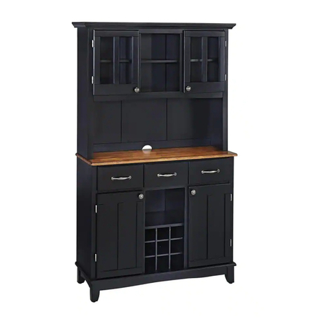
Kitchen Island
50 94210-
Carton 5010 941 is also needed for assembly.-
C.
Base
1 pc.
I.
Rail
2 pcs.
J.
Base
1 pc.
K.
Plinth
1 pc.
P.
Front Rail
1 pc.
R.
Support
1 pc.
Refer to later page(s) of these
instructions for drawer assembly.
F.
Back Panel
1 pc.
G.
Back Panel
1 pc.
H.
Front Panel
1 pc.
O.
Back Stretcher
1 pc.
S.
Support
2 pcs.
V.
Door
1 pc.
W.
Door
1 pc.
Assembly Instructions 2/10
Figure 1
STEP 1
Insert Cam Lock Screws into pre-drilled holes in Plinths (D), (E), Black Panels (F), (G) and
Front Panel (H), then tighten. (See Figure 1)
Orientate Magnets so Arrow labels on back of Magnets point in same direction as
Arrow labels on Back Panels (F) and (G), then attach Magnets to Back Panels (F) and (G)
with Wood Screws for Magnet into pre-drilled holes. (See Figure 2)
H
IMPORTANT
Use a soft cloth between these parts and the floor.
Do not use power tools above 8 volts to assemble.
Do not tighten all the bolts until each part is properly assembled.
The unit must be level to work properly. Use the included adjustable levelers to level.
Keep Hex Wrench as the bolts may need to be tightened in the future.
DE
Figure 2
F
G
Cam Lock Screw
Wood Screw for Magnet
Magnet
Cam Lock Screw
Arrow labels point in same direction
Cam Lock Screw
STEP 4
Attach unit from Step 2
to unit from Step 3
with Cam Locks.
Attach Rails (I) to unit
with Cam Locks.
Attach Front Panel (H) to unit
with Cam Locks.
Assembly Instructions 3/10
STEP 2
Orientate Base (C) so Arrow labels on Base (C)
point to Plinths (D) and (E), then attach Plinths (D)
and (E) to Base (C) with Cam Locks. (See Figure 3)
D
E
C
STEP 3
Attach Back Panel (F)
to Back Panel (G).
F
G
H
I
I
Cam Lock
Arrow labels point to Plinths (D) and (E)
Cam Lock
Figure 3
Assembly Instructions 4/10
STEP 5
Insert Cam Lock Screws into pre-drilled holes in Plinth (K),
Side Panels (L), (M) and Back Stretcher (O), then tighten.
STEP 6
Attach Middle Panel (N) to Base (J) with
Head Cap Bolts. (See Figure 4)
Note: Arrow label indicates front of
Middle Panel (N).
Attach Plinth (K) to unit with Cam Locks.
Figure 4
N
J
K
K
O
L
M
Cam Lock
Head Cap Bolt
Cam Lock Screw
Arrow label at front
Assembly Instructions 5/10
STEP 7
Attach Side Panel (L) to unit with
Cam Locks and Wood Screw
for Plinth.
Attach Front Rail (P) to unit with
Cam Lock.
P
L
Q
O
Wood Screw for Plinth
Cam Lock
Cam Lock
STEP 8
Attach Back Stretcher (O) to
unit with Cam Lock.
Attach Divider (Q) to
unit with Cam Lock.
Assembly Instructions 6/10
STEP 9
Attach Side Panel (M) to
unit with Cam Locks
and Wood Screw for Plinth.
M
STEP 10
Turn unit to its upright position.
Attach Top (B) to unit with Head Cap Bolts.
B
Head Cap Bolt
Cam Lock
Wood Screw for Plinth
Assembly Instructions 7/10
STEP 11
Insert Cam Lock Screws into pre-drilled holes in Supports (S),
then tighten.
STEP 12
Attach Supports (S) to Support (R) with Cam Locks.
S
S
R
S
S
STEP 13
Attach unit form Step 12 to unit from Step 10.
Cam Lock Screw
Cam Lock
Assembly Instructions 8/10
STEP 14
Turn unit from Step 4
to its upright position.
Insert Cam Lock Screws
into pre-drilled holes
in unit from Step 4,
then tighten.
Attach unit form Step 4
to unit from Step 13
with Cam Locks and
Head Cap Bolts (short).
STEP 15
Insert Adjustable Pins into
front panel and back panels
at desired level.
Place Shelves (X) into position.
Attach Doors (T) and (U) to
unit by sliding door hinges
into front panel hinges.
(See Figure 5)
Attach Top (A) to unit with
Head Cap Bolts.
Figure 5
Head Cap Bolt (short)
Cam Lock
Cam Lock Screw
U
T
X
X
X
A
Head Cap Bolt
Adjustable Pin
Assembly Instructions 9/10
Part List
STEP 18
Attach Handle with Machine Screws.
STEP 17
Slide Drawer Bottom (Z5) into groove.
Attach Drawer Bottom (Z5) to unit with
Wood Screws (short).
Drawer (Z)
Z5
Z2
Z3
Z4
Z1
STEP 16
Attach Drawer Front (Z1) and Drawer
Back (Z2) to Drawer Side (Z3) with
Wood Screws (long).
Attach Drawer Side (Z4) to unit with
Wood Screws (long).
Z1.
Drawer Front
2 pcs.
Z2.
Drawer Back
2 pcs.
Z3.
Drawer Side
2 pcs.
Z4.
Drawer Side
2 pcs.
Z5.
Drawer Bottom
2 pcs.
Handle
Machine Screw
Wood Screw (short)
Wood Screw (long)
Bottom
Roller at back
Assembly Instructions 10/10
Figure 7Figure 6
V
Z
Z
W
Y
Y
Machine Screw
Handle
Adjustable Pin
STEP 19
Insert Adjustable Pins into side panels at desired level.
Place Shelves (Y) into position.
Attach Doors (V) and (W) to unit by sliding door hinges into side panel hinges.
Attach Handles to Doors (V) and (W) with Machine Screws. (See Figure 6)
Slide Drawers (Z) into position.
Level unit by adjusting the adjustable levelers on bottom of unit. (See Figure 7)
NEVER
use glass cleaners on
finished furniture. Ammonia
chemically attacks the finish.
allow liquids to remain on furniture.
Absorption causes parts to warp
and split and finishes to delaminate.
NEVER
CARE INSTRUCTIONS
Do not use rubber
based placemats.
PREVENT
DISCOLORING
Do not use commercial
waxes and polishes.
PREVENT
YELLOWING
Do not place hot
objects on surface.
PREVENT
FINISH DAMAGE
Do not write
directly on surface.
PREVENT
MARKING
Do not use power tools
above 8 volts to assemble.
PREVENT
CRACKING
Do not place
in direct sunlight.
PREVENT
FADING
with a soft cloth moistened
in lukewarm soap and water.
Buff with a dry clean cloth.
CLEAN
Home Styles will provide replacements free of charge for missing or damaged hardware or parts within 30 days of
purchase. Digital images of the defective parts may be required. If the product was not purchased from an authorized
retail affiliate, Home Styles is under no obligation to provide replacement parts. Parts are not available for fully assembled
items nor are parts available for sale. Replacements for missing or damaged hardware or parts may be requested at:
www.homestylesfurniture.com/customer-service/replacement-parts
Home Styles Customer Service: www.homestylesfurniture.com,
[email protected], 888-680-7460, 877-831-0319

Other Home Styles Indoor Furnishing manuals
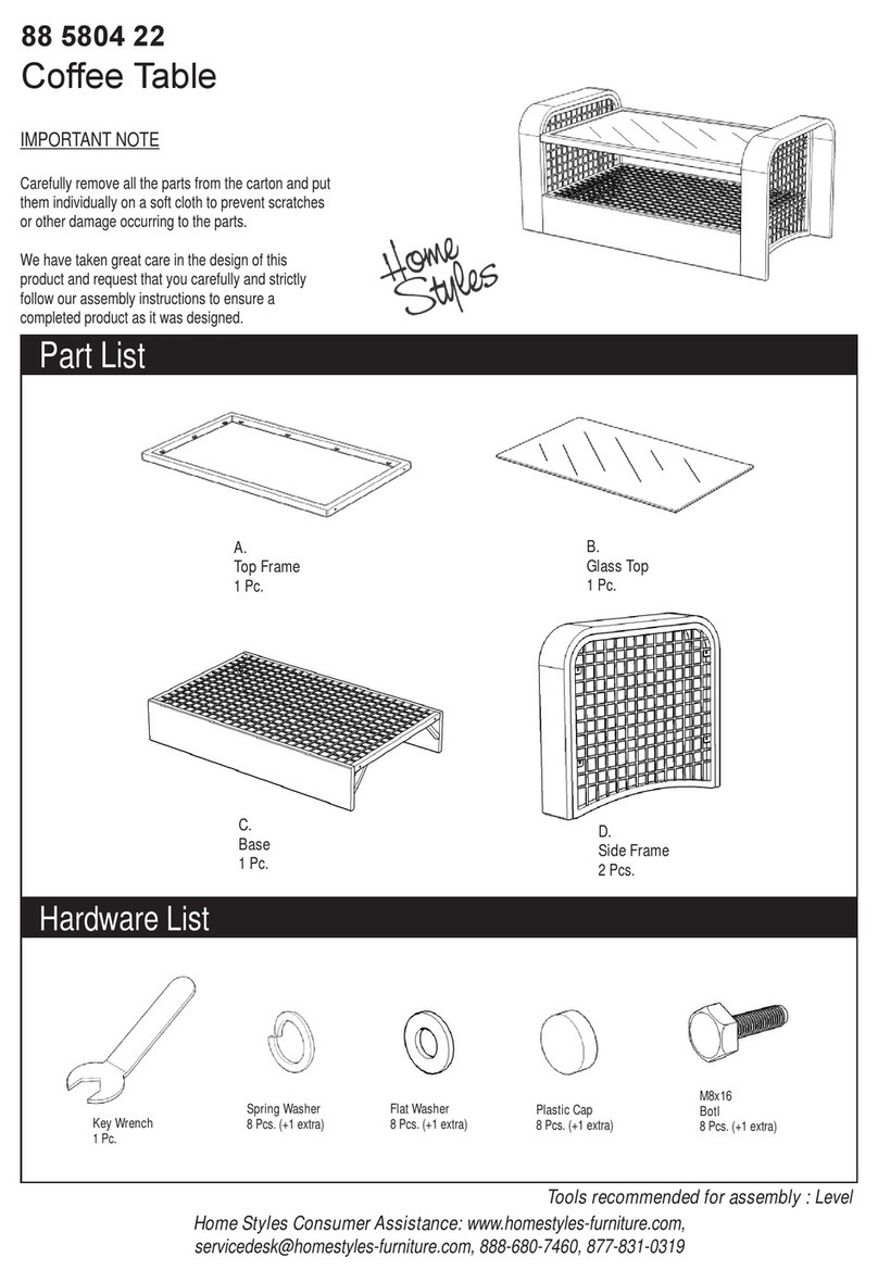
Home Styles 88 5530 401 User manual

Home Styles

Home Styles 88 5530 401 User manual

Home Styles 4514-95 User manual

Home Styles

Home Styles 4514-95 User manual

Home Styles Cabin Creek  88 5411 49 User manual

Home Styles

Home Styles Cabin Creek 88 5411 49 User manual

Home Styles Naples Corner Entertainment User manual

Home Styles

Home Styles Naples Corner Entertainment User manual

Home Styles 88 5531 772 User manual

Home Styles

Home Styles 88 5531 772 User manual

Home Styles 88 5700 30 User manual

Home Styles

Home Styles 88 5700 30 User manual

Home Styles 5094 941 User manual

Home Styles

Home Styles 5094 941 User manual

Home Styles 20 05507 0078 User manual

Home Styles

Home Styles 20 05507 0078 User manual

Home Styles Art & Crafts 88 5181 42 User manual

Home Styles

Home Styles Art & Crafts 88 5181 42 User manual

Home Styles 20 05503 0164 User manual

Home Styles

Home Styles 20 05503 0164 User manual

Home Styles 20 05664 0026 User manual

Home Styles

Home Styles 20 05664 0026 User manual

Home Styles Cabin Creek Baker's Rack User manual

Home Styles

Home Styles Cabin Creek Baker's Rack User manual

Home Styles 20 05520 0932 User manual

Home Styles

Home Styles 20 05520 0932 User manual

Home Styles 20 05507 0070 User manual

Home Styles

Home Styles 20 05507 0070 User manual

Home Styles 20 05525 0061 User manual

Home Styles

Home Styles 20 05525 0061 User manual

Home Styles 5004 692 User manual

Home Styles

Home Styles 5004 692 User manual

Home Styles 88 5181 31 User manual

Home Styles

Home Styles 88 5181 31 User manual

Home Styles 88 5436 09 User manual

Home Styles

Home Styles 88 5436 09 User manual

Home Styles 20 05663 0026 User manual

Home Styles

Home Styles 20 05663 0026 User manual

Home Styles 88 5560 32 User manual

Home Styles

Home Styles 88 5560 32 User manual

Home Styles 88 5168 80 User manual

Home Styles

Home Styles 88 5168 80 User manual

Home Styles 5605-34 User manual

Home Styles

Home Styles 5605-34 User manual

Home Styles 88 5559 80 User manual

Home Styles

Home Styles 88 5559 80 User manual

Home Styles 88 5003 941 User manual

Home Styles

Home Styles 88 5003 941 User manual

Popular Indoor Furnishing manuals by other brands

Regency LWMS3015 Assembly instructions

Regency

Regency LWMS3015 Assembly instructions

Furniture of America CM7751C Assembly instructions

Furniture of America

Furniture of America CM7751C Assembly instructions

Safavieh Furniture Estella CNS5731 manual

Safavieh Furniture

Safavieh Furniture Estella CNS5731 manual

PLACES OF STYLE Ovalfuss Assembly instruction

PLACES OF STYLE

PLACES OF STYLE Ovalfuss Assembly instruction

Trasman 1138 Bo1 Assembly manual

Trasman

Trasman 1138 Bo1 Assembly manual

Costway JV10856 manual

Costway

Costway JV10856 manual
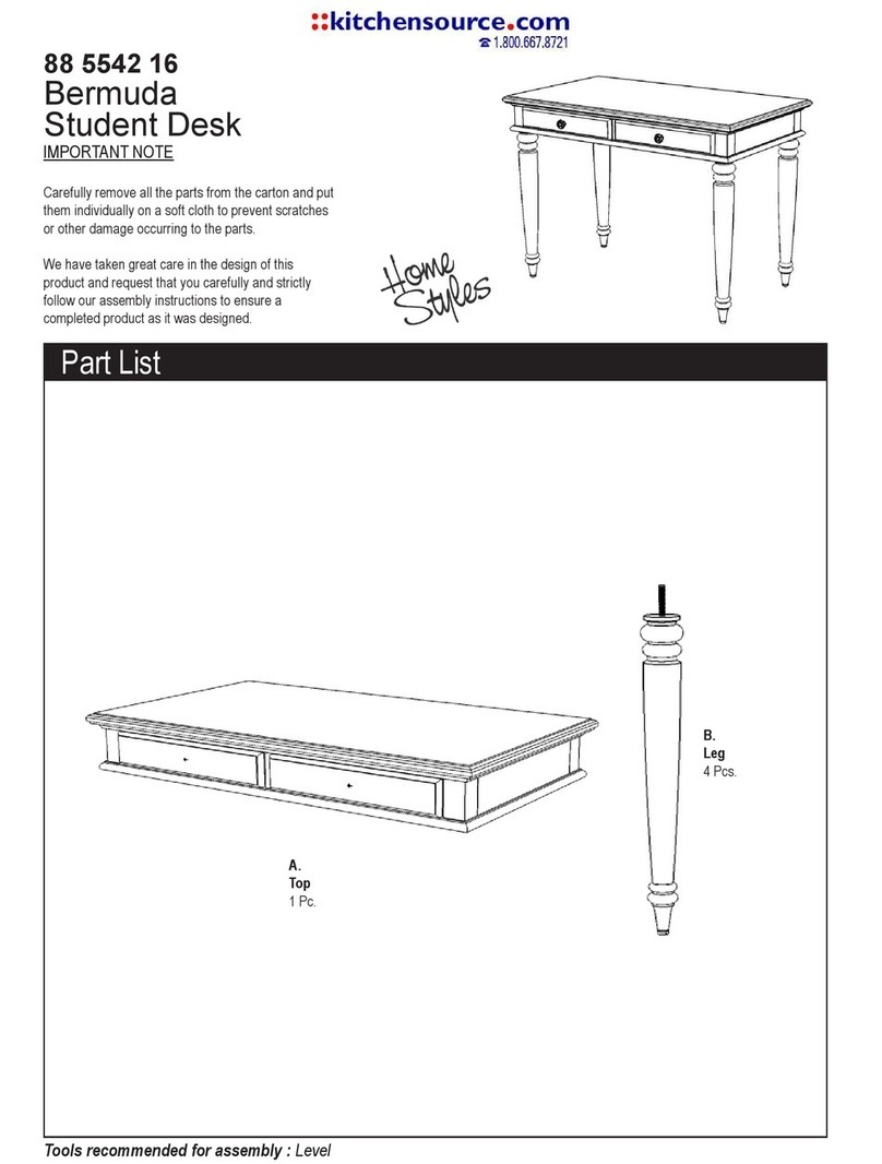
moss DESIGN Caisson Credenza Assembly instructions

moss DESIGN

moss DESIGN Caisson Credenza Assembly instructions

Aquaglide FULL DECK 15.0 owner's manual

Aquaglide

Aquaglide FULL DECK 15.0 owner's manual

AREBOS AR-HE-SW30 user manual

AREBOS

AREBOS AR-HE-SW30 user manual

Till-Hilft Fulda 87005.330 Assembly instructions

Till-Hilft

Till-Hilft Fulda 87005.330 Assembly instructions

Twoey Outside 2010 quick start guide

Twoey Outside

Twoey Outside 2010 quick start guide

Hettich Easys 200 operating instructions

Hettich

Hettich Easys 200 operating instructions

The bedboss RELAX 404 Series owner's manual

The bedboss

The bedboss RELAX 404 Series owner's manual

Oeseder Möbelindustrie Bern 991 720 Assembly instructions

Oeseder Möbelindustrie

Oeseder Möbelindustrie Bern 991 720 Assembly instructions

Costway HW68469 user manual

Costway

Costway HW68469 user manual

Next ALIX A27743 Assembly instructions

Next

Next ALIX A27743 Assembly instructions

BROSA Hans Assembly guide

BROSA

BROSA Hans Assembly guide

Prodigg MINIKA PBA015T-FUR installation manual

Prodigg

Prodigg MINIKA PBA015T-FUR installation manual

manuals.online logo
manuals.online logoBrands
  • About & Mission
  • Contact us
  • Privacy Policy
  • Terms and Conditions

Copyright 2025 Manuals.Online. All Rights Reserved.