manuals.online logo
Brands
  1. Home
  2. •
  3. Brands
  4. •
  5. Honeywell
  6. •
  7. Control System
  8. •
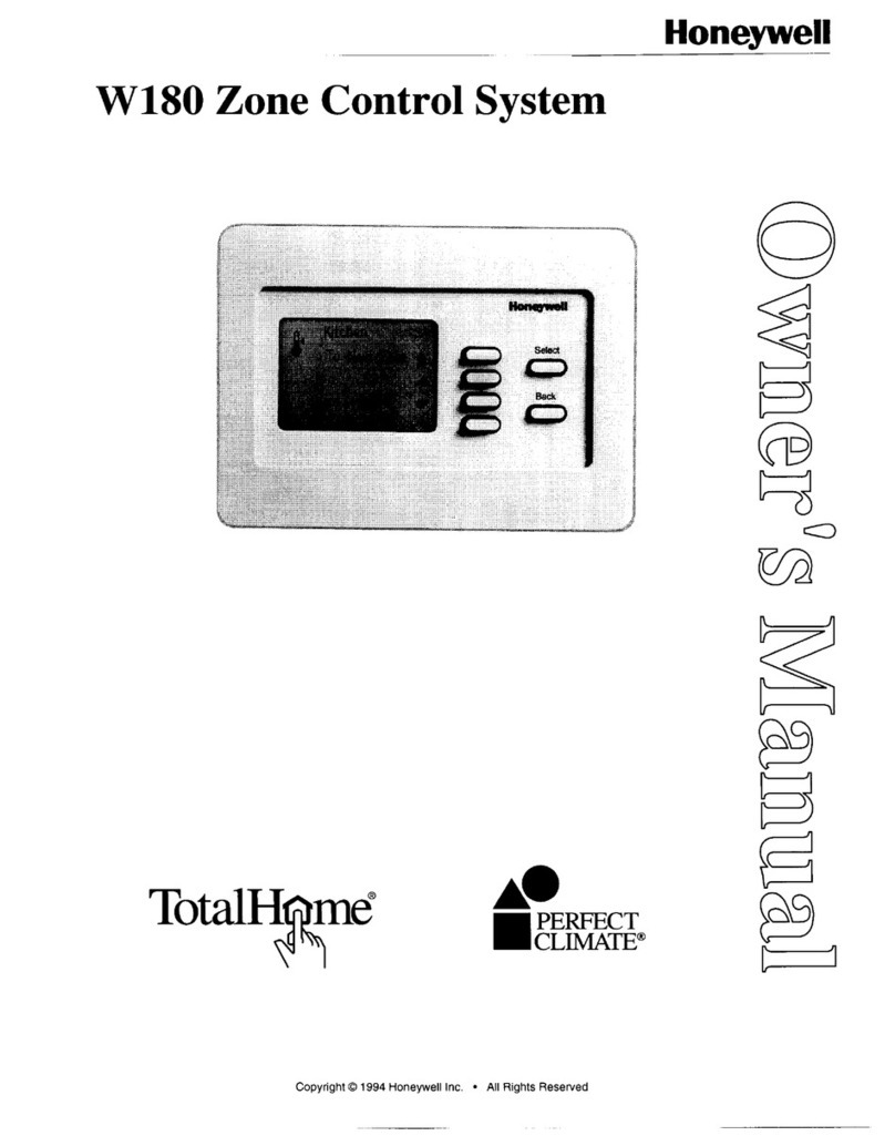
  9. Honeywell W7080A User manual

Honeywell W7080A User manual

Honeywell
THIS SOLID-STATE SYSTEM ISACOMPONENT
FOR COMPONENT FIELD REPLACEMENT
FOR THE RANCO EA3 LODAPT SYSTEM. THE
BASIC SYSTEM CONTROLS UP TO 12 ZONE
DAMPERS, 3 HEATING STAGES, 3 COOLING
STAGES, AN INTEGRATED ECONOMIZER,
AND MODULATING VALVES FOR HOT WATER
AND CHILLED WATER. OPTIONAL UNITS
PROVIDE CONTROL OF UPTO 12ADDlTlONAL
ZONES, 5 STAGES OF ELECTRIC HEAT,
VARIABLE AIR VOLUME (VAV) SYSTEM FAN,
AND A FOURTH STAGE OF COOLING.
0
Modulated DC
voltage
signal from zone
thermostat, modified by zone discharge
sensor, provides direct control of
associated zone damper.
•i Pilot duty SPDT relays control heating
and cooling stages.
0
Economizer uses
M745K
or
M745L
motor
to provide true first stage of cooling, using
outdoor air whenever possible.
•i System switches all stages off when
power is intermpted; switches all stages
on when power is restored. Compressor
turn on time delays must be incorporated
for each compressor.
0
Power supplies in
W7080A
Load Analyzer
and W7084A Zone Adder are short-circuit
protected. Short circuits of 24 Vdc from
load analyzer or zone adder will not
damage their power supplies.
0
Night setback and cooling shut-down for
individual or all zones by adding a time
clock.
HG/KH Form
Number
63-4179
7/90
©
Honeywell
1990
SYSTEM COMPONENTS:
All
components
of
the
W7080
Multizone
Control
System
are
briefly described in this
section.
For detailed information
on
C7046B and
C7100B
sensors. T7080A,B Thermostats and
W7081A Limit Controller, refer to the associated specifica-
tion
sheets
(form
number
in parenthesis): C7046B
(60-
2350),
C7100B
(60-2539),
T7080A,B
(60-2527),
W7081A
(60-
2512).
C7046B
Temperature
Sensor
-
(Ranco
TR1-1001)
is
non-
averaging type with 6 in.
[152
mm]
probe
for
use in
ducts
where
space
does
not
permit
t
longer
C7100B.
C7100B
Averaging
Temperature
Sensor
-
(Ranco
TR1-
1002,-1003)
installed
in hot
deck,
cold
deck
and
mixed air
ducf
to
provide
limit signals for limit controller operation.
Also
installed
in
discharge
air duct of
each
zone to provide
anticipation
for the T7080 Thermostat. Sensor probe
length
is 13 in. [330 mm].
H205A
Enthalpy
Controller
-
(Ranco
(15)
senses
heat
content (temperature and humidity) of outdoor air.
Allows
use
of
outdoor
air for
free
cooling.
S7666A
Simulator
-
(Ranco
TEI)
portable
unit
provides
check of
system
by substituting
adjustable
DC
voltage
for
zone
thermostat
and
sensor signals.
T7080A,B
Solld
State,
Dual
Setpoint
Thermostat
-
(Ranco
TR3, TR4) modulates zone dampers and
supplies
load demand signal to load analyzer. Single voltage ramp
design
has variable, 3 to 30°F
[I.7
to
16.7%]
dead bard.
For complete T702OA.B information, refer to form number
60-2527,
T7080A
has
a
built-in
sensor;
T7080B
requires
remote
sensor.
W7080A
Load Analyzer
-
(Ranco
EA3) provides SPOT
relay
switching of
three
stages
of healing and
three
stages
of cooling and modulating
output
to
economizer
and valve
motors
in response to highest healing and cooling demand
from
zone
thermostats. Analyzer is source cl 24 Vdc power
for
zone
thermostats
sensors,
and
W7081A
Limit
Controller.
W7081A
Limit
Controller
-
(Ranco
EA5-G3002)
provides
economizer control in addition to hot and
cold
deok
selec-
table
limik.
Saves
energy by maintaining
selected
tempera-
ture limik of hot and
cold
decks
when
zone
demands
are
reduced.
For
complete
W7081A
information,
refer
to
form
number W-2512.
W7082A Integrator
Analyzer
-
(Ranco
EA5-C6001-35)
op-
tional
unit
controls
system
blower
in VAV systems in
response
to
zone
demand. During
decreased
demand, the
W7082A
reduces
fan
output, thus saving
energy.
(Requires
additional
blower
equipment. not
available
from Honeywell.)
W7083A
Electric
Heat
Seq.
-
(Replaces
Ranco
EA5-C0501)
optional
unit
switches
up to five ON/OFF
stages
of
electric
heat,
provides
stage
turn
on
delay
on
power restoration.
W7084A
Zom Adder
-
(Ranco
EA5-C9001,-C9002)
option-
al
unit
permits
the
addition
of up to
12
zones
to
system.
196325s Fourth
Stage
Cooling
Board
-
(Ranco
EA5-
C9100
optional
unit
permits
addition
of a fourth stage of
coding
to
system.
ELECTRICAL RATINGS:
Voltage
and
Frequency
-
24
Vac,
50/60
HZ.
Maximum
Power
Consumption
-
W7080A
IO VA;
W7081A, 0.29 VA;
W7082A,
1.5 VA; W7083A,
1.4 VA; W7084A, 3 VA.
Contact
Ratings
(SPDT
pilot
duty
relays)
-
See
Table
I.
SYSTEM INPUT
SIGNALS:
See
Table
2.
SYSTEM OUTPUT SIGNALS:
See
Table 3.
STAGE DIFFERENTIALS AND THERMOSTAT DEAD
BAND:
See
Figure
1.
Table 1
Relay Contact
Ratings
for
W7080A,
W7083A,
1953258
Voltage Inrush Running
Contact
Vac
VA VA
Normally
open
24
I
240
60
1
12Oi240
I
750
1
75
Normal
dosed 24 75 30
1
20/240 240 40
Table 2
System
Input
Signals
TO
Signal (Vdc) From
W7080A 2-22 T7080A,B
W7081A
2-12 (LO) W7080A,
W7084A
12-22 (HI)
W7083A 2-12 W7080A,
W7081A
195325B
12-24
W7080A,
W7081A
M745K,L 14-17
W7081A
M744D, M745G.P 4-7
W7081A
Table 3
System
Output
Signals
From Signal (Vdc)
TO
T7080A 2.22 W7080A,
W7082A,
W7084A,
M734
10.5-13.5 M734
W7080A, 2-12
W7081A,
W7084A (LO)
W7083A,
195325B
W7080A 12-22 W7081A,
W7084A (HI) W7083A,
195325B
W7081A
W7082A
14-17
4-7
0
to
-10
M745K.L
M744D,
M745G,P
Inverter
(VAV fan
motor
control
COLD DECK LOW
LIMIT:
Limits
cold
deck
temperature
to
selectable
setpoints
of
45°F.
50°F
or
55°F [7.2°C, 10% or
12.8°C].
HOT DECK
HfGH
LIMIT:
Limits hot
deck
temperature
to
selectable
setpoints
of
90°F,
110°F
or
130°F [32.2°C,
43.3°C
or
54.4%).
Economizer
motor modulates outdoor air damper
to
mink
mum
position
when mixed air
temperature
is
below
setpoint
of
W7081A
Limit
Controller.
This
setpoint
is selectable
to
50°F.
55°F
or
60°F
[10°C,
12.8°C
or
15.6°C],
with
a
10°F
[5.6°C]
fixed
throttling
range.
tNTEGRATOR MINIMUM OUTPUT:
Selectable from 0
to
-8
Vdc
(0
to
60
percent
fan
motor
speed).
ZONE DlSCHARGE SENSOR AUTHORITY:
20:1,
which
means
a
20°F
[11.1°C]
rise
at the
zone
dii
charge
sensor
produces
a
voltage
change
equal
to a 1°F
[0.5°C]
rise
at the space
thermostat.
AMBIENT TEMPERATURE RISE:
Operating- -40
to
150°F [-40 to 65°C]
Shipping-
-30
to
150°F
[-34
to
65°C]
MOUNTING:
The
W7080A,
W7081A,
W7082A,
W7083A,
W7084A
units
each
attach
with
four
screws
through
mounting holes in the
base (saws not provided). The 195325B Fourth Stage
coding
Board
can
be
mounted on a Rat
surface.
Sea
in-
dividual specification
sheets
for
mounting
details.
UNDERWRfTERS
LABORATORIES INC.
CCMPONENT
RECOGNIZED:
Fib
number
SA481, Guide number SDFY2D (applies
to
W7080A, W7083A and 19253258 units
only).
ADDITIONAL SYSTEM COMPONENTS:
C7100B
(13
In.)
Averaging
Temperature
Sensor
-
One
sensor
in
hot
deck,
one
sensor
in
cold
deck
and one
sen-
sor
in mixed
air
to supply
the
three sensor input signals re-
quired
by
the
W7081A
Limit Controller. Also,
one
sensor
is
installed in each
zone
discharge duct to
supply
anticipation
to
the
T7080A
Zone
Thermostat.
Where
space
is
insufficient
for he 13 in.
[304.8
mm]
probe
of the
C7100B,
the C7046B single point temperature sen-
sor,
with 6 in.
[152.4
mm] probe, may be installed.
1353258
Fourth
Stage
Cooling
Board
-
Controls
opera-
tion
of
two
stage
compressor
in
the
system.
Mounts
separately
from
other
components.
H205A
Enthalpy
Controller
-
Controls
economizer
opera-
tion in response to
enthalpy
(total
heat
content) of outdoor
air.
Signals
economizer
to
close
outdoor
air damper
(or
modulate m minimum
position)
when
enthalpy
is
above
H205
setpoint
and
to
open damper on a call for cooling
when
enthalpy
is
below
setpoint.
Figure 2
-
Mounting Dimensions for W7080A
W7082A,
W7083A,
W7084A
Units in
Inch
[mm In
brackets]
Nonspring
Return
Motors
-
M734J,
M744D
have
a solid
state balance relay, operate on 24
Vac,
50/60
Hr.
Spring
Return
Motors
-
M746G,K,L,P
motors
have
solid-
state
balance
relay, require separate 24 Vac,
50/60
Hz
power
supplies.
Time Delay Relays
-
To improve stability
of
the
system
and minimize energy
use,
five
minute
turn
on time delays
should
be
added
to
all heating and cooling loads.
These
relays should be wired between
cooling
and heating stage
switching outputs
(W7080A
Load
Analyzer
W7083A
Electric
Heat Sequencer and 1953258 Fourth Stage Cooling Board)
and the heating and cooling equipment.
SYSTEM ACCESSORIES:
Transformers: AT20-20 VA; AT7240 VA;
AT88-75
VA
4
Analyzer can also be
used
to
power
stage
relays in the
W7083A
Electric
Heat
Sequencer
(if
used).
The
M744
and M745
motors
each
require a separate transformer
to
ensure
electrical
isolation.
‘NEVER
GROUND
THE I
SECONDARY OF ANY TRANSFORMER USED TO
POWER
ANY
SYSTEM
COMPONENT. I
Q209A
Minimum
Position
Potentiometer
-
Mounts
direct-
iy
on
M734,
M744,
M745 motors;
controls
minimum
open
position
of damper.
Q605 Damper Linkage
-
Connects motor to damper.
in-
cludes motor
crank
arm.
Q618
Valve
Linkage
-
Connects
Modutrol
motor
to
modulating hot or chilled
water
valves.
S963A
Remote
Mlnlmum
PositIon
Potentiometer
-
Provides
remote
manual control
of
minimum open
position
of economizer
motor.
Modulatlng
Water
Valves
-
Use appropriate valve with
Super
Modutrol
motor and
Q618
Linkage
to
provide
propor-
tional
control of hot or chilled
water
flow.
Compressor
Ambient
Lockout
Thermostat
-
Use
with
direct expansion
cooling
system to prevent compressor
operation when outdoor air temperature falls below
economizer setpoint.
-
T675A
Temperature Controller.
-
L6018CTemperatureController.
Economizer Changeover Controller
-
Holds economizer
at minimum position whenever outdoor air temperature
or
en-
thalpy is
above
controller setpoint.
-
H205A1038
or
H205A1046
Enthalpy
Controller.
-
T675A
Temperature
Controller.
-
L6a%cT-nuc-
Nlght
Setback
-
Provides
heating setback of 6 to
22°F
[3.3
to
12.2°C].
Requires
connection
of a 1% resistor and
S6005
Time
Clock
contact
conncected
between
Terminals 3,
7 or 6; and 5 of
T7080A
or
T7080B
Thermostat.
-
T675A
Tsn~
cammu=
-
L4o,acT-~Gmu0ua
S43
Sail
Switch
-
Activates
circuits when minimum
airflow
is maintained in duct. Deactivates circuit
below
minimum
airflow.
1914448 Metal Cover
-
Designed
to
protect the
W7080A,
W7081A,
W7082A,
W7083A
and
W7084A
components when
mounted
on
open
surface.
Overall
dimensions of units
with
metal
cover
in
place:
6%
in. long,
4+‘1’16
in. wide, 49’w in.
high
[168.3
x
108.5
x
122.2 mm].

This manual suits for next models

5

Other Honeywell Control System manuals
Honeywell BCS 3600 User manual

Honeywell

Honeywell BCS 3600 User manual

Honeywell ACC 50 User manual

Honeywell

Honeywell ACC 50 User manual

Honeywell C7400 User manual

Honeywell

Honeywell C7400 User manual

Honeywell vk41 series User manual

Honeywell

Honeywell vk41 series User manual

Honeywell VR8304 User manual

Honeywell

Honeywell VR8304 User manual

Honeywell touchpoint Pro User manual

Honeywell

Honeywell touchpoint Pro User manual

Honeywell Excel 500 User manual

Honeywell

Honeywell Excel 500 User manual

Honeywell LYNX Touch Security System User manual

Honeywell

Honeywell LYNX Touch Security System User manual

Honeywell Experion LX User manual

Honeywell

Honeywell Experion LX User manual

Honeywell SmartVFD User manual

Honeywell

Honeywell SmartVFD User manual

Honeywell 5701 User manual

Honeywell

Honeywell 5701 User manual

Honeywell SPZ-8000 Manual

Honeywell

Honeywell SPZ-8000 Manual

Honeywell Experion LX Manual

Honeywell

Honeywell Experion LX Manual
Honeywell W180 User manual

Honeywell

Honeywell W180 User manual

Honeywell Experion LX 8 series User manual

Honeywell

Honeywell Experion LX 8 series User manual

Honeywell Farenhyt Series Operating instructions

Honeywell

Honeywell Farenhyt Series Operating instructions

Honeywell Experion PKS User manual

Honeywell

Honeywell Experion PKS User manual

Honeywell SILENT KNIGHT SK-Zone-6 User manual

Honeywell

Honeywell SILENT KNIGHT SK-Zone-6 User manual

Honeywell Excel 800 Installation and operation manual

Honeywell

Honeywell Excel 800 Installation and operation manual

Honeywell KAP 140 User manual

Honeywell

Honeywell KAP 140 User manual

Honeywell MCBA14C Service manual

Honeywell

Honeywell MCBA14C Service manual

Honeywell LYNX Touch L7000 Series User manual
Honeywell

Honeywell LYNX Touch L7000 Series User manual

Honeywell 5704 User manual

Honeywell

Honeywell 5704 User manual

Honeywell VR8205 User manual

Honeywell

Honeywell VR8205 User manual

Popular Control System manuals by other brands

Chinowing T31 user manual

Chinowing

Chinowing T31 user manual

RichAuto A1X manual

RichAuto

RichAuto A1X manual

Dahua NKB user manual

Dahua

Dahua NKB user manual

Burkert 8644 AirLINE quick start

Burkert

Burkert 8644 AirLINE quick start

ATA OACIS-1XC Quick installation guide

ATA

ATA OACIS-1XC Quick installation guide

VALTIR Triton Barrier TL-2 Assembly manual

VALTIR

VALTIR Triton Barrier TL-2 Assembly manual

Rubix POD2 user guide

Rubix

Rubix POD2 user guide

B&B Molders Nautilus P1 Installation instructions & owner's manual

B&B Molders

B&B Molders Nautilus P1 Installation instructions & owner's manual

DSE DSE6110 MKII Operator's manual

DSE

DSE DSE6110 MKII Operator's manual

Exhausto VEX370H Mechanical assembly

Exhausto

Exhausto VEX370H Mechanical assembly

Tekelec EAGLE 5 Hardware

Tekelec

Tekelec EAGLE 5 Hardware

Pentair EasyTouch installation guide

Pentair

Pentair EasyTouch installation guide

Hitachi YUTAKI M Installation & operation manual

Hitachi

Hitachi YUTAKI M Installation & operation manual

Setec DRIFTER owner's manual

Setec

Setec DRIFTER owner's manual

Raven DCS 410 Installation & service manual

Raven

Raven DCS 410 Installation & service manual

Omron TJ1/GRT1 Hardware reference manual

Omron

Omron TJ1/GRT1 Hardware reference manual

Intewa RAINMASTER Eco-FS Installation and user manual

Intewa

Intewa RAINMASTER Eco-FS Installation and user manual

Optimus SMM-8SA QuickGuide Installation

Optimus

Optimus SMM-8SA QuickGuide Installation

manuals.online logo
manuals.online logoBrands
  • About & Mission
  • Contact us
  • Privacy Policy
  • Terms and Conditions

Copyright 2025 Manuals.Online. All Rights Reserved.