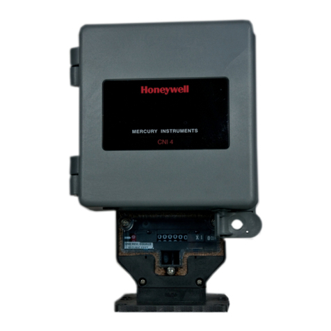
Honeywell CNI4 User manual

CNI4 Operating and Installation Guide
FD-602 | Version 2 | September 2017
Honeywell Process Solutions | Mercury Instruments
512 Virginia Drive, Ft. Washington, PA 19034 USA
855 251-7065 – United States & Canada | 302 669-4253 – Outside the United States
MI-TAC-Support@Honeywell.com | www.honeywellprocess.com

Copyright 2017 . Honeywell Process Solutions. All rights reserved.
Information in this document is subject to change without notice. The software described in
this document is furnished under a license agreement or non- disclosure agreement. The
software may be used or copied only in accordance with the terms of those agreements. No
part of this publication may be reproduced, stored in a retrieval system, or transmitted in any
form or any means electronic or mechanical, including photocopying and recording for any
purpose other than the purchaser's personal use without the written permission of Honeywell
Process Solutions.
For technical assistance, email at MI-TAC-Support@Honeywell.com.

1 Introduction 1
2 Product Features 3
3 Specifications 4
4 Safety 6
4.1 Limited Warranty 6
4.2 Intrinsic Safety for Hazardous Locations 6
4.3 Label 6
4.4 Security 7
5 Instrument Mounting Options 8
5.1 Wall Mounting 8
5.2 Meter Mounting 9
6 Electrical Assemblies 11
6.1 Internal Battery Power Options 11
6.2 Simplified Wiring Diagrams (with internal modem) 12
7 Getting Started 14
7.1 Introduction 14
7.2 Installing the SIM Card 15
7.3 Connecting power supply 15
7.4 Connecting the external pulse inputs 18
7.5 Disconnecting the serial interface cable 18
7.6 Configuring the Pulse Accumulator 19
7.7 Configuring the Cloud Link 4G Modem 21
7.8 Restore the original serial cable connection 22
7.9 Close and lock the door 23
8 Adding a CNI4 Site in MasterLink 24
9 Appendix 28
9.1 CNI4 Index Base 28
9.2 Call-in and Call-out 30
9.3 Installation Drawing 31
9.4 Item Code Types 32
9.4.1 Item Code List 32
CONTENTS

1 Introduction
The CNI4 is a 4G/LTE, battery-operated, easy to configure dual-channel pulse data logger designed to
support most commercial & Industrial (C&I) smart metering/automatic meter reading (AMR) analog as
well as 2G/3G modem-based applications. The basic CNI4 assembly includes a Cloud Link 4G Modem to
provide cellular communication.
With this advanced cellular pulse data logger, both input channels and stored consumptions can be
independently scaled to different units of measure, providing maximum value and flexibility.
The CNI4 Pulse Data Logger is designed for low-power and outdoor operation.
It is ideal for call-In applications involving meter data management (MDM) and can directly connect to
PowerSpring or couple with the InvisiConnect software to interface with third-party MDM systems.
The CNI4 is fully integrated in the Honeywell Mercury® Instruments ecosystem and is easy to program
through its Bluetooth Low Energy interface and associated configuration software. The unit can be
configured using the same MasterLink software that is used to configure Honeywell Mercury electronic
volume correctors, data loggers and modems. No additional software is required. In addition, MasterLink
is now available as an app that can be installed on IOS and Android devices.
The CNI4 is CSA Class I Div 2 approved, making it a perfect solution for gas measurement applications
where safety is always a concern
Two independent pulse sources may be connected to the input channels, each having its own 3.5vdc
wetting voltage. Since the two channels act as independent accumulators, typical installations might
include:
a. One pulse source (pulse transmitter or meter pulse) connected to either Ch1 or Ch2.
b. Two separate pulse sources (pulse transmitters or meter pulses): Ch1 for the first source and Ch2
for the second source.
c. Pulse outputs from one volume corrector connected to both channels, Ch1 for corrected volume
pulses and Ch2 for uncorrected volume pulses.
In an operational CNI4, pulses received at either input are assigned a fixed amount of volume via their
respective Input Pulse Value selections. Additional pulse scaling can be applied using their respective
Input Pulse Scaling items (if needed) before the pulses are stored (added) to their respective accumulated
totals. Ch1 versus Ch2 volume units can be independently scaled. The number of digits (from 4 to 8
digits) can also be assigned for both channels. Below are the items associated with Accumulated
Volumes:
Description Ch1 Item# Ch2 Item#
Input Pulse Value 098 912
Input Pulse Scaling (this feature is normally not needed) 114 913
1 Introduction
Honeywell | 1

Description Ch1 Item# Ch2 Item#
Accumulated Volume 002 910
Incremental Accumulated Volume 226 911
Accumulated Volume Units 092 458
Accumulated Volume # of Digits 097
1 Introduction
Honeywell | 2

2 Product Features
Two independent channels
Low power consumption
Field-proven composite material case with hinged door
Easy software-based configuration
Multi-vendor data collection capability
Force-a-call feature
Wireless communications Cloud Link 4G cellular modem
2 Product Features
Honeywell | 3

3 Specifications
Environmental
-25°C to +65°C
Ambient Humidity: 0 to 95% non-condensing
Software
Configuration: MasterLink R510+ (Windows, IOS, Android)
Data Collection: TDS, PowerSpring, DC2009, Itron MV90, and other third-party software
providers
Data Inputs
Max frequency: 3Hz - 50% duty cycle, 10 Hz – 40% duty cycle
Memory
1 year+ of hourly/10 user-specified log items
Pulse Input Circuit
Full temperature range
Max wetting current provided = 35 microamps
Max transmitter leakage current - 7 microamps
Max Pulser + Line Resistance = 200 ohms
Max line length = 300 feet
Parameter Conditions Min. Typical Unit
LTE Connectivity Band 2, 4, 5, 13 and 17
Receiver Input Sensitivity@
ARP (ch.bandwidth 5MHz)
LTE 700 Band 17 -97 -102 dBm
LTE 700 Band 13 -98 -103 dBm
LTE 850 Band 5 -98 -104 dBm
LTE AWS Band 4 -100 -103 dBm
LTE 1900 Band 2 -98 -103 dBm
3 Specifications
Honeywell | 4

Power
2 D-cell Lithium disposable battery pack for pulse accumulator
2 D-Cell Lithium disposable battery pack with super-capacitor for cellular radio
Certifications
Class 1, Division 2, Group D
PTCRB
Verizon, AT&T, Rogers
FCC
Security
SSL/TLS 1.2
Enclosure
20% glass-filled polycarbonate
Weight: 3.7 lbs
Wall-mount or meter-mount
Communications
4G/LTE cellular modem
Operates with major carriers in North America: Certified with AT&T, Verizon, Rogers Falls back to
UMTS/HSPA and GSM/GPRS, T3C
Bluetooth Low Energy interface can be used for wireless configuration
Wireless specifications:
LTE: Five band, 700 (Bd13)/700 (Bd17)/850 (Bd5)/ AWS (Bd4)/1900MHz (Bd2)
UMTS/HSPA+: Triple band, 850 (BdV)/AWS (BdIV)/1900MHz (BdII)
GSM/GPRS/EDGE: Quad band, 850/900/1800/1900MHz
Bluetooth Low Energy: v.4.0 (2402- 2480MHz)
3 Specifications
Honeywell | 5

4 Safety
4.1 Limited Warranty
Mercury Instruments, Inc. warrants all instruments covered by this manual to be free from defects in
material and workmanship under normal use and service of this product. If returned to our factory,
transportation charges prepaid, within 4 years of the original purchase shipment date, Mercury
Instruments agrees to repair or replace any instrument which its examination reveals to have been
defective due to faulty workmanship or material. All obligations or liabilities on Mercury Instruments part
is to repair or replace warranty instruments, and does not include any other type of claims or damages,
including but not limited to consequential damages following the use or misuse of instruments sold by it.
Mercury Instruments reserves the right to, at any time make changes, modification or enhancements to
this product without prior notification. This warranty is in lieu of all other warranties, express or implied.
No agent is authorized to assume for Mercury Instruments any liability except as set forth above.
4.2 Intrinsic Safety for Hazardous Locations
The Mercury Instruments CNI4 is certified by CSA (CUS) for Class I, Div-2, Group D hazardous locations
when installed in accordance with CSA (CUS) control drawing 40-6144 in this manual.
Warning:Use only Mercury Instruments manufactured battery packs with part numbers
as specified on the certification label or control drawing. Use of third party battery packs
voids product warranty, voids intrinsic safety certifications and may impair safety.
Related Item:Installation Drawing
4.3 Label
Check the following material label and serial number label:
CNI4NAME
MODEL NO.
S/N
XXXXXXXX
YYYY/MM
MERCURY
INSTRUMENTS
Country of origin:
Mexico
HOneywell
This device complies with
Part 15 of the FCC Rules.
Operation is subject to the following two
conditions: (1) This device may
not cause harmful interference, and
(2) This device must accept any
interference received,including interference
that may cause undesired operation.
Figure 4-1: Label - Serial Number
4 Safety
Honeywell | 6

Figure 4-2: Label - Material
4.4 Security
The CNI4 device can be configured through the following interfaces:
Serial
Bluetooth
Cellular
A valid user name and password are required for accessing the Cloud Link 4G Modem. The device
supports different privilege levels like Read / Write, Read Only.
The CNI4 supports whitelisting of cellular communications. You can configure up to 10 host IP addresses
for the device to allow specific hosts in case of call outs.
For communication over Cellular interface the Cloud Link 4G Modem can use SSL/TLS 1.2 Certificates for
mutual authentication and secure connection. The following certificates can be loaded for secure
communication over cellular interface.
Client Certificate
Server Certificate
Private Key(Encrypted)
CA Certificate
4 Safety
Honeywell | 7

5 Instrument Mounting Options
A number of options are available for conveniently installing the CNI4 product. These should be clearly
specified at the time of order to ensure that everything the field technician needs is available at the time
of product installation.
5.1 Wall Mounting
Where a flat wall surface is available, such as on the side of a building or shed, stainless steel “hangers”
can be utilized. Illustrated below is the rear view of a CNI4, along with associated mounting dimensions
(in inches).
Figure 5-1: Wall Mounting Tabs and Dimensions
The lockwasher contacts directly with the enclosure, then the hanger, the flat washer, and lastly the
screw. To secure, tighten the screw until snug, but do not over-tighten.
Recommended wall and fasteners:
Recommended Wall Brick Wall
Fasteners STAINLESS STEEL THREAD FORMING ¼ dia-1.25” length
5 Instrument Mounting Options
Honeywell | 8

5.2 Meter Mounting
Where it is desired to have an index base mounted directly to a meter, the UMB (Universal Mounting
Bracket) option is available. The advantages of this package is that the entire instrument can be mounted
without any concerns about routing external meter pulse signal wires. Mounting the UMB index base is
possible on rotary, turbine, and diaphragm gas meters that have a rotating instrument drive output. This
includes American, Rockwell, Romet, Roots, or Schlumberger meters.
The UMB housing may be rotated about the base plate so that the instrument and index will face in any
of the four directions. Remove all four screws which attach the base plate to the bracket housing. Replace
and tighten the four screws after you have repositioned the UMB housing.
Figure 5-2: CNI4 with Universal Mounting Bracket (UMB)
The bottom side of the UMB meter index is seen below, along with the ‘wriggler’ mechanism.
Figure 5-3: Bottom View of the Universal Mounting Bracket (UMB)
5 Instrument Mounting Options
Honeywell | 9

The following illustration provides reference dimensions for the base plate. All dimensions are in inches.
Figure 5-4: Universal Mounting Bracket (UMB) Hole Pattern
5 Instrument Mounting Options
Honeywell | 10

6 Electrical Assemblies
6.1 Internal Battery Power Options
Shown below is the dual-cell lithium power pack. This pack is inserted onto the enclosure door with the
right-side of the metal plate tilted inwards first, and then snapping secure on the left side. Removal is the
opposite, and it is a simple matter of pressing outwards against the plastic lever.
Figure 6-1: Lithium Battery Pack Mounting
Component Battery pack Part Number
Pulse Accumulator Dual-cell lithium power pack 40-6048
Cloud Link 4G Modem Single Lithium D-Cell 51203165-100
6 Electrical Assemblies
Honeywell | 11

6.2 Simplified Wiring Diagrams (with internal modem)
Notes:
For Canadian installations, install in accordance with Canadian electrical code part 1.
For US installations install in accordance with the national electrical code, ANSJ/NFPA 70,
article 504.
Warning: substitution of components may impair suitability for CLASS 1, DIV2 battery packs
must be replaced only in a non-hazardous atmosphere.
Tb2 is for pulse inputs: connections to tb2 can be made via conduit as per note#1 or without
conduit if one of the following pulse generator options used passive, resistive, non-energy
storing device or devices having entity parameters conforming to table1. These pulse generators
can be located in DIV2 or non hazardous locations. Maximum cable length 200ft. Any
combination of the options for pulse generators are not to be connected simultaneously.
6 Electrical Assemblies
Honeywell | 12

OUTPUT PARAMETERS
OPEN CIRCUIT VOLTAGE Voc Uo 3.9V
SHORT CIRCUIT VOLTAGE lsc lo 0.40mA
POWER OUTPUT Po Po 0.39mW
MAXIMUM ALLOWABLE CAPACITANCE Ca Co 1μF
MAXIMUM ALLOWABLE INDUCTANCE La Lo 100mH
Table 6-2: Output Parameters
Do not connect 51203165-100 battery pack and external power simultaneously to the Cloud
Link 4G modem.
For DIV2 installations only, the enclosure must have a rigid metal conduit hub for wiring entry.
For CNI4 devices without a modem, the serial port connection must be made by routing the
serial cable through the conduit.
The cables must be installed and supported in an appropriate manner such that the tensile
stress at the cable glands is avoided.
6 Electrical Assemblies
Honeywell | 13

7 Getting Started
7.1 Introduction
The CNI4 comprises of two components: The Pulse Accumulator and the Cloud Link 4G Modem.
You can use the MasterLink Software (R510.1 or higher) to configure the Pulse Accumulator and the
Cloud Link 4G Modem as two independent sites, using the USB-to-serial cable (40-6147-kit).
Connector to the
Pulse Accumulator
Connector to the
Cloud Link 4G Modem
USB connection
to the PC
Figure 7-1: The USB-to-serial cable (40-6147-kit)
One end of the cable has a USB connector and the other end includes a male and female connector. The
male (black) connector connects to the Cloud Link 4G Modem and the female (green) connector connects
to the Pulse Accumulator.
Steps to configure the CNI4:
Step 1:Open the door of the CNI4 and install the SIM Card.
Step 2:Power-up the CNI4 - battery or external power supply.
Step 3:Connect the external pulse inputs (for wall mounted only)
Step 4:Disconnect the serial cable interfacing the Pulse Accumulator and the Cloud Link 4G Modem.
Step 5:Configure the Pulse Accumulator.
Step 6:Configure the Cloud Link 4G Modem.
Step 7:Restore the original serial cable connection.
Step 8:Close and lock the door.
7 Getting Started
Honeywell | 14

7.2 Installing the SIM Card
1. Lift the cover on the Cloud Link 4G modem.
2. Slide the white SIM card holder to the right, then lift the left edge.
3. Insert a SIM card into the slot provided and close the card holder.
4. Slide the SIM card holder to the left until it snap locks.
5. Close the cover.
7.3 Connecting power supply
The CNI4 can be powered using battery or external power.
To connect the battery packs to the Cloud Link 4G Modem
1. Install the Cloud Link battery packs with the positive terminal on top.
2. Tie wrap the batteries to the metal plate.
3. Connect the female connector from the first battery to the male connector of the second battery.
4. Remove the warning label as shown in the picture (on next page), and then remove the dummy
battery connector plug on the Cloud Link.
7 Getting Started
Honeywell | 15

5. Attach the connector from the second battery to the Cloud Link battery connector.
6. Wrap the extra wire using a cable tie.
To connect the battery pack to the Pulse Accumulator
1. Install the Pulse Accumulator battery pack on the left side of the battery plate.
2. Connect the Pulse Accumulator battery pack to the Y cable.
3. Wrap the extra wire using a cable tie
7 Getting Started
Honeywell | 16

To setup external power supply
1. Remove the housing of the cable gland and route the power cable through it.
2. Connect the power cable to the 3-pin power connector on the Pulse Accumulator board.
3. Connect the other end of the power cable to an external power source (5V to 16V, 2A peak current).
7 Getting Started
Honeywell | 17
Other manuals for CNI4
2
Table of contents
Other Honeywell Data Logger manuals

Honeywell
Honeywell CNI4 User manual

Honeywell
Honeywell CNI4 User manual

Honeywell
Honeywell Vocollect Application guide

Honeywell
Honeywell E-Mon IDR Series User manual

Honeywell
Honeywell DL230 User manual

Honeywell
Honeywell Minitrend QX Series User manual

Honeywell
Honeywell SX User manual

Honeywell
Honeywell Minitrend User manual

Honeywell
Honeywell eZtrend V5 User manual