4Rev. 3 User Manual
Honeywell Industrial Wireless Wireless Base Radio
Section 3: Installation
3.1: Mechanical Installation In this section mechanical installation instructions are discussed for the
various setup capabilities of the Honeywell Wireless Base Radio. The
subsections are as follows:
3.1.1: Base Radio Positioning
3.1.2: Base Radio Mounting
Warning
During installation do not apply force to the in-
strument housing or antenna. Use a proper wrench
for all installations. Failure to use correct installa-
tion procedures can cause damage to the Base
Radio.
!!
The Honeywell Wireless Base Radio is a rugged device, but it will give
much better service if installed with careful consideration as noted in this
manual. It may be utilized in any service so long as care is exercised to
prevent exposing the sensing elements to excess stress or temperature.
Installation practices have a lot to do with these service parameters and the
life that you can expect from your Honeywell Wireless Base Radio. The
main considerations for installation are covered below.
Give careful consideration to the environment where you will be installing
your instrument. Avoid installations that expose the device to excess tem-
perature, high vibration, considerable shock, or exposure to dripping con-
densate or corrosive materials. Also avoid installing the device in an un-
serviceable location.
Most often these problems can be avoided with some thought at the time
of installation. The practices noted below are generally recommended, but
they can only act as a guideline and cannot cover all possible variations.
The final installation must be made at the discretion and approval of the
user. You must be the judge of the actual installation.
3.1.1: Base Radio Positioning Correct positioning of the Base Radio will ensure the best performance of
the device. Because the Base Radio is the central communication device of
all Transmitters that are assigned to it. The Base Radio should be located
in an area that is somewhat central to all the Transmitters.
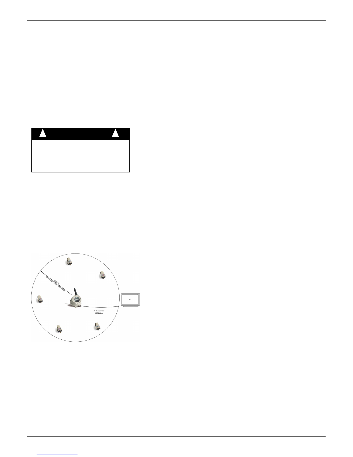
Figure 3.1 is a picture of a general Base Radio layout. The maximum dis-
tance is determined by a number of factors, including the Baud Rate Set-
ting. When planning the positioning of the Base Radio try to place the
Base Radio in an elevated position to avoid human traffic interference.
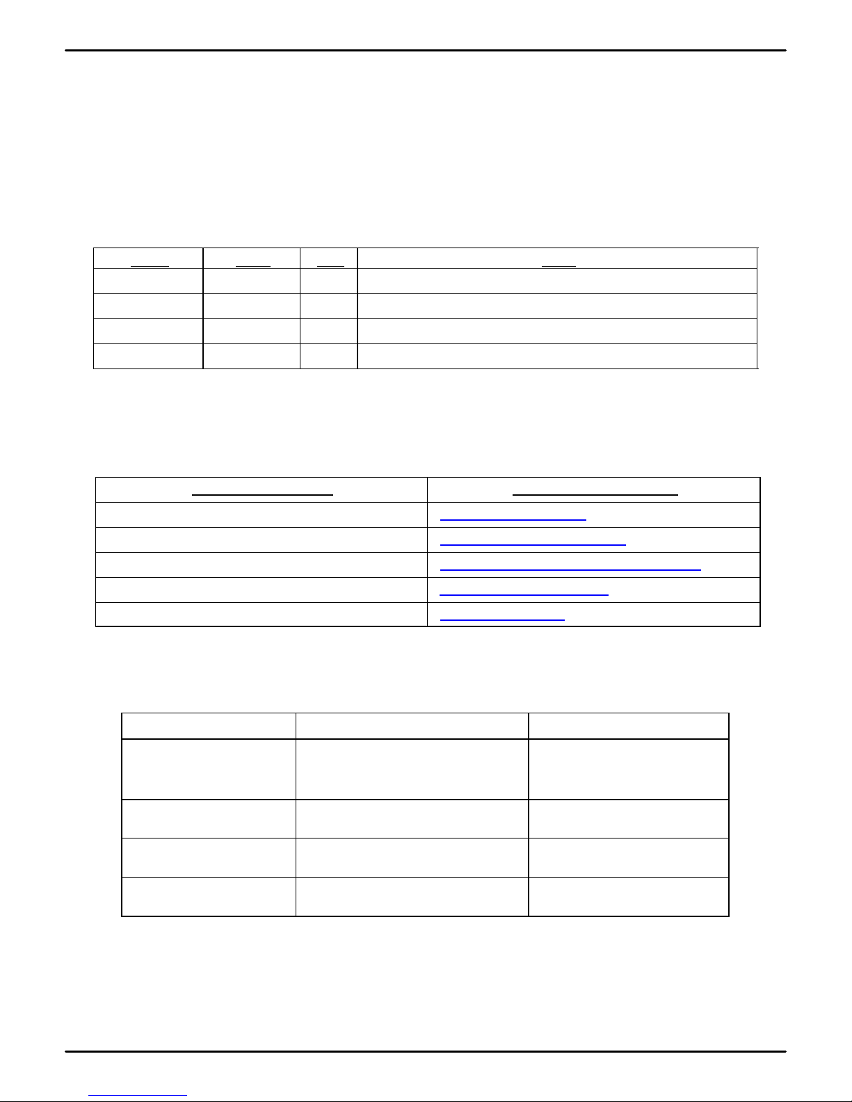
Remember, the approximate line of sight range between a Transmitter and
Base Radio is determined by the Baud Rate as listed below:
•76.8K -76.8 Kbaud, Range of 450ft
•19.2K -19.2 Kbaud, Range of 1200ft
•4.8K -4.8 Kbaud, Range of 2000ft
Note: This range is reduced by the amount of RF Noise present, obstruc-
tions, and the material properties of those obstructions.
Only place the Base Radio in ambient operating temperatures of -40°F to
185°F (-40°C to 85°C).
Make sure you have power and communication to the Base Radio avail-
able. (See Electrical Installation section)
Because there are so many setup possibilities we cannot cover them all. A
correct setup would make sure that the above warnings are heeded, and
that the Transmitter and Base Radio are capable of communication. The
RF Placement Procedure section of the Transmitter Guide will help you to
determine if you have a selected the correct installation points and orienta-
tions for your application.
Figure 3.1: General Layout