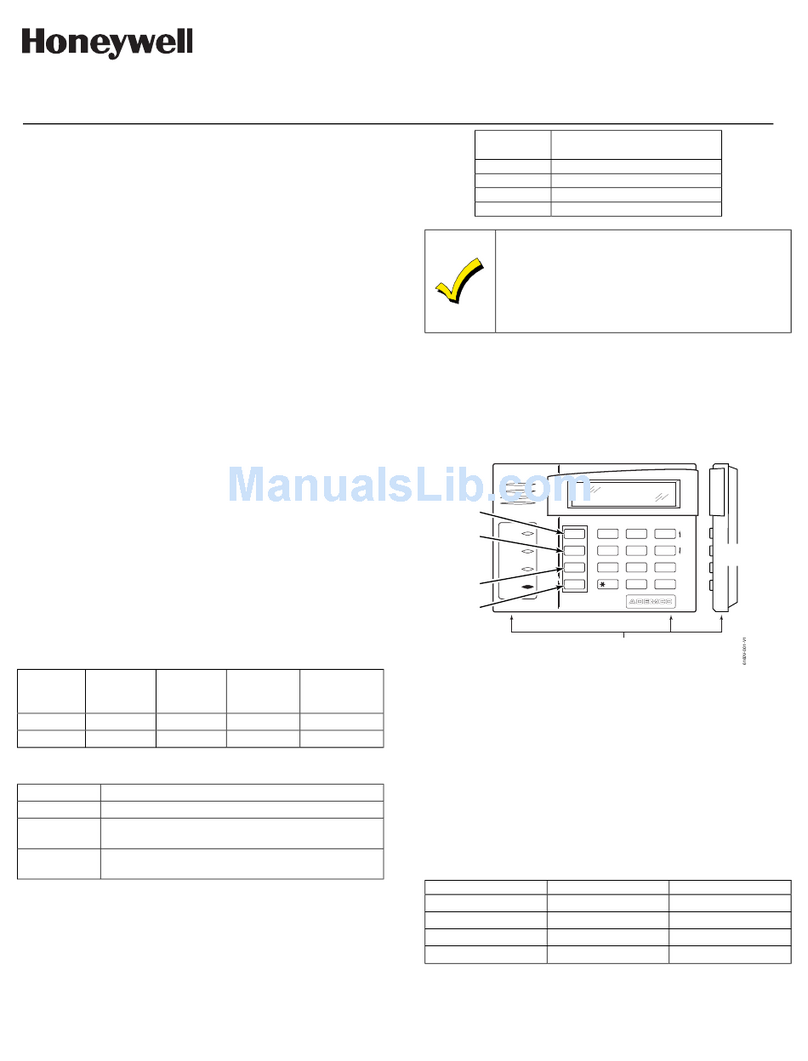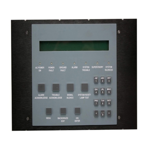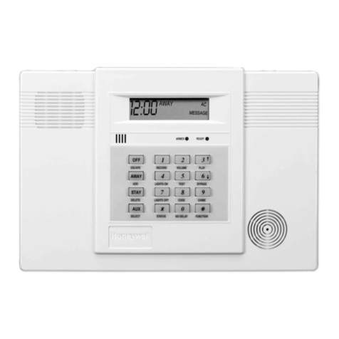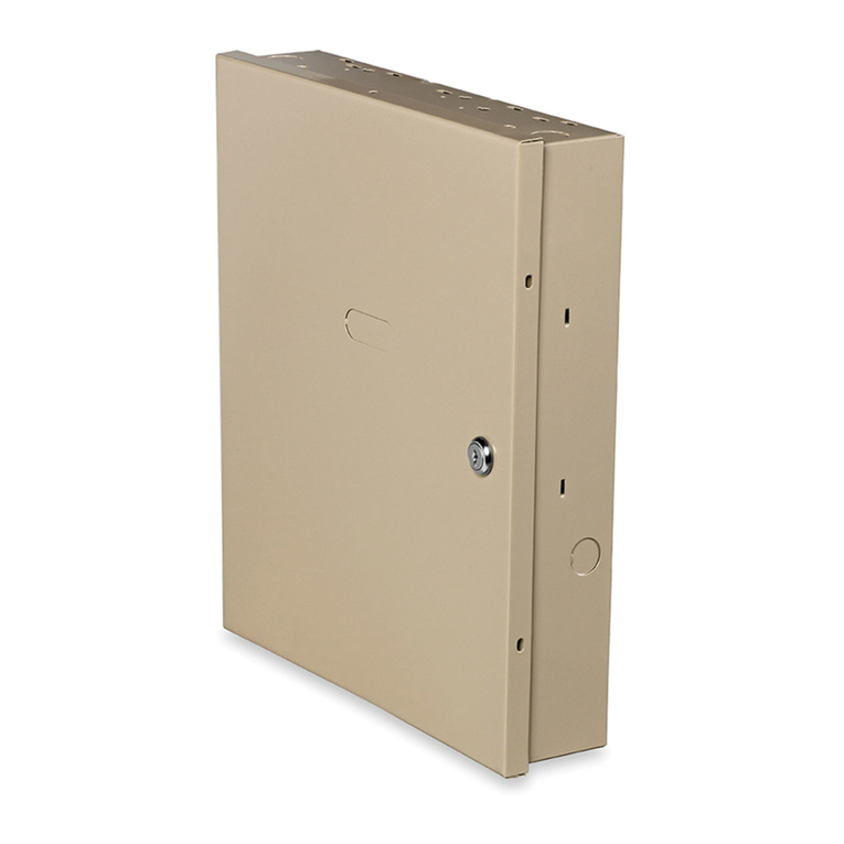
INSTALLATION INSTRUCTIONS
® U.S. Re
istered Trademark
Cop
ri
ht © 2001 Hone
well • All Ri
hts Reserved
U.L. 4-01
Intelliguard 9000™
SECURITY SYSTEM
WARNING: This e
uipment
enerates, uses, and can radiate radio fre
uenc
ener
, and if not installed and used in accordance
with the Instructions Manual, ma
cause interference with radio communication. It has been tested and found to compl
with the
limits for a Class A computin
device pursuant to Subpart J of Part 15 of FCC Rules, which are desi
ned to provide reasonable
protection a
ainst such interference when operated in a commercial environment. Operation of this e
uipment in a residential
area is likel
to cause interference, in which case, users at their own expense will be re
uired to take whatever measures ma
be
re
uired to correct the interference. An
unauthorized modification of this e
uipment ma
result in the revocation of the owner's
authorit
to continue its operation.
GENERAL
The Intelli
uard 9000™ Securit
S
stem
I9000
protects
offices, warehouses and other businesses as part of the
Enterprise Buildin
s Inte
rator™
EBI
S
stem. The I9000
uses Hold-up
HU
Detectors to alert outside help to a current
hold-up and Hall Effect Door Switches
HEDS IV
to monitor
door openin
s. Other detection devices and outputs can be
linked to the I9000 when the
conform to the re
uirements in
form no. 74-3035, Intelli
uard 9000 Specification Data.
OVERVIEW
These instructions describe the steps for wirin
and
connectin
the I9000 devices, pro
rammin
field devices and
connectin
the I9000 to the EBI Securit
S
stem. The
do not
contain instructions for pro
rammin
the I9000 with a PC.
Refer to form no. 74-3046, Intelli
uard 9000 Pro
rammer’s
Guide for pro
rammin
instructions. Also see form no. 74-
3035, Intelli
uard 9000 Specification Data and form no. ZD34-
002-100, EBI Installation Guide.
ASSUMPTIONS
It is assumed that:
— The location of each part is planned before installation
be
ins.
— Installer has a basic understandin
of electronics.
—La
out plan for I9000 is complete.
There is a specific order for installin
the I9000. Refer to the
followin
installation instructions.
The installer ma
chan
e
the order for mountin
and connectin
the hardware, when
appropriate.
INSTALLATION
When Installing this Product . . .
1. Read these instructions carefull
. Failure to follow the
instructions can dama
e the product or cause a hazard-
ous condition.
2. Check the ratin
s
iven in the instructions and on the
product to make sure the product is suitable for
our
application.
3. The installer must be a trained, experienced, licensed
where re
uired
service technician.
4. After completin
installation, use these instructions to
check out the product operation.
Components
— 8003-217 Remote Intelli
ent Power Suppl
RIPS
.
— 8003-220 Area Ke
pad
KID
.
— 8003-238 Complete 6-Input Concentrator
BIC-6
.
— 8003-242 2-Input Concentrator
BIC-2
.
— 8003-277 Ke
pad Control Center
CC2
.
— 8003-283 Hall Effect Door Switch
HEDS IV
Complete
Assembl
includes Sensor and Ma
net Assembl
.
— 8003-284 2-Input Concentrator Hold-up Actuator
BIC-2 HU
.
— 8003-286 Multiple Output Module
MOM
.
— 8003-332 I9000 Control Unit
CU
in casin
.
— Transformer, 16 Vac, 37 to 40 VA.
— RS-232 cable and connectors.
— RS-485 cable and connectors.
NOTE: The MOM currentl
is not CE certified. In countries
that re
uire certification for all parts, confi
ure one or
more BIC-6s as an output device. Confi
urin
the
BIC-6 for output is described later in these instruc-
tions.
Parts Available (Not Included)
— 8003-302 HEDS IV
L
Bracket.
—7003-162 AX-5L Conduit Adapter.
—4545-059 BIC-2/BIC-2 HU Optional Rela
.
