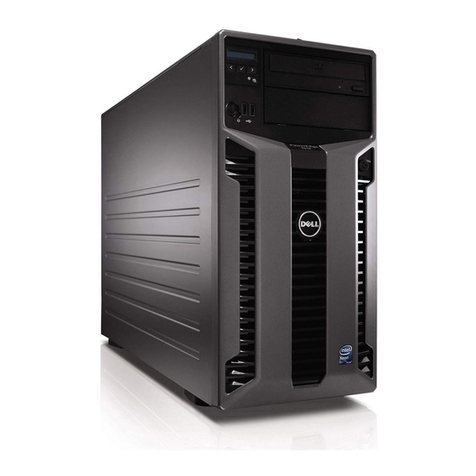
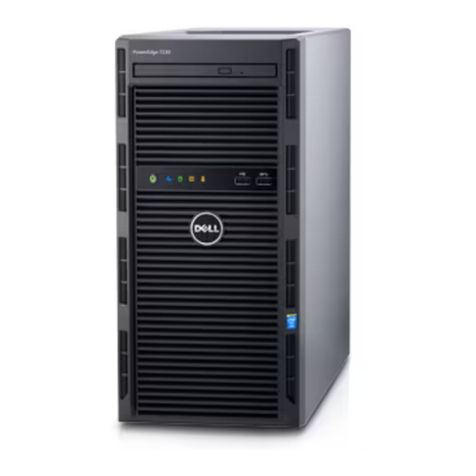
Honeywell T320 Technical manual

T320 Honeywell Server Planning, Installation and Service
Guide
HWDOC-X239-en-I
August 2020

Disclaimer
This document contains Honeywell proprietary information. Information contained herein is to be used
solely for the purpose submitted, and no part of this document or its contents shall be reproduced,
published, or disclosed to a third party without the express permission of Honeywell International Sàrl.
While this information is presented in good faith and believed to be accurate, Honeywell disclaims the
implied warranties of merchantability and fitness for a purpose and makes no express warranties
except as may be stated in its written agreement with and for its customer.
In no event is Honeywell liable to anyone for any direct, special, or consequential damages. The
information and specifications in this document are subject to change without notice.
Copyright 2020 - Honeywell International Sàrl
- 2 -

Contents 3
Chapter 1 - About this Document 7
1.1 Revision history 9
Chapter 2 - Planning 10
2.1 Overview 10
2.1.1 Software requirement 11
2.1.2 BIOS configuration 11
2.2 Description 11
2.2.1 Honeywell server model number 12
2.2.2 Electronics configuration 12
2.2.3 Electronics module 12
2.2.4 Standard features of Dell T320 13
2.2.5 Slots configuration 14
2.2.6 Optional features 14
2.2.7 Power cords 15
2.3 Platform information 15
2.3.1 Honeywell documentation 15
2.3.2 Dell documentation 15
2.4 LCN node slot requirements 17
2.5 Experion nodes slot requirement 17
2.5.1 Default configurations for FTE 17
2.5.2 FTE supervisory (Default) 17
2.5.3 Cnet configuration using PCIC interface 18
2.6 Memory configuration for Dell T320 18
2.6.1 4GB, consisting of two 2GB RDIMM for Pre-MLK servers 19
2.6.2 8GB, consisting of four 2GB RDIMM or two 4GB RIDMM for Pre-MLK servers 19
2.6.3 8GB, consisting of two 4GB RIDMM for MLK servers 20
2.7 System specifications 21
2.7.1 Microprocessor 21
2.7.2 Memory 22
2.7.3 Raid controller 22
2.7.4 Optical disk drive 22
2.7.5 Video 22
2.7.6 Network interface 22
2.7.7 Power 22
2.7.8 Environmental 22
- 3 -

2.7.9 Physical – form factor 24
2.7.10 Drive bays 24
2.7.11 Maximum vibration 24
2.7.12 Shock 24
2.7.13 Altitude 25
2.7.14 External peripherals 25
2.7.15 Drives 25
2.7.16 External ports 25
2.7.17 Management 25
2.7.18 Hard disk drive specifications 26
2.7.19 Removable media specifications 26
2.7.20 Storage and media devices 26
2.7.21 Mouse and keyboard 27
2.7.22 Monitor 27
2.7.23 Video cable 27
2.8 Industrial regulatory compliance 27
2.8.1 Electromagnetic Compatibility 27
2.8.2 Safety compliance 28
2.9 Light industrial regulatory compliance 28
2.9.1 Electromagnetic Compatibility 28
2.9.2 Safety compliance 29
Chapter 3 - Installation 30
3.1 Tasks for installing the server 30
3.1.1 Before you begin 30
3.2 Power and grounding requirements 30
3.2.1 Grounding consoles and cabinets 31
3.3 Cabinet spacing requirements 31
3.3.1 Unused cabinet spaces 31
3.4 Installing Dell T320 server and connecting cables 32
3.4.1 Honeywell server back panel connections 32
3.4.2 Installing the server using the fixed rail mounting kit model TP-SPCMF1 34
3.4.3 Installing the server using the slide tray mounting kit model TP-SPCMS1 35
3.4.4 Connecting the cables 37
3.4.5 Install air duct baffles and blank panel front covers in cabinet 38
3.5 Starting the server 40
3.5.1 Turning on the power 40
3.5.2 Configuring RAID in Dell T320 server 41
- 4 -

3.5.3 Starting the TDC emulator services 42
3.5.4 Checking the LCNP4e/LCNP4e2 status 42
Chapter 4 - Operation 43
4.1 Server overview 43
4.1.1 Front view of Dell T320 43
4.1.2 Rear view of Dell T320 44
4.2 Network connections 45
4.2.1 Ethernet network 46
4.2.2 LCN cables 46
4.2.3 LCN network 46
4.2.4 LCN connections 46
4.2.5 MAU connection 47
4.2.6 ControlNet Network 47
4.3 Configuring ControlNet interface card 48
4.3.1 Installing ControlNet card inside Magma chassis 48
Chapter 5 - Servicing 49
5.1 Removing the front bezel 49
5.1.1 To remove the front bezel 49
5.2 Removing the side cover 50
5.2.1 To remove the side cover 50
5.3 Servicing the LCNP4e/LCNP4e2 51
5.3.1 Replacing the LCNP4e/LCNP4e2 board 51
5.4 Servicing the hard disk drives and power supply 53
5.4.1 References 53
5.5 Servicing Honeywell options 54
5.5.1 LCN node slot requirements 54
5.5.2 Slot requirements for General Ethernet and FTE node setup 55
5.6 Adding additional memory 56
5.6.1 Prerequisites 56
5.6.2 To add additional memory 56
5.7 Installing hot spare hard drive 58
5.7.1 To insert the hot spare hard drive 58
5.8 Installing PCIC card in Dell T320 server using Magma 58
5.8.1 To insert the Magma PCIe card 58
5.9 Verifying correct BIOS settings 60
5.9.1 Entering the BIOS 61
- 5 -

5.9.2 BIOS settings for Tab 51155517-100 61
5.9.3 BIOS settings for Tab 51155517-200 66
5.9.4 BIOS settings for Tab 51155517-300 71
5.9.5 BIOS settings for Tab 51155517-400 76
5.9.6 BIOS settings for Tab 51155517-500 83
5.9.7 BIOS settings for Tab 51155517-600 88
5.9.8 Exiting the BIOS 94
5.10 Spare parts 94
5.11 Troubleshooting 95
5.11.1 Integrated Dell Remote Access Controller 6 (iDRAC6) issue 95
- 6 -

ABOUT THIS DOCUMENT
This document contains installation and service information for the Dell PowerEdge T320 server. The
instructions and service information contained here address the server itself, and assumes that the
associated network communication equipment has been pre-installed by the Honeywell factory or has
manuals dedicated to its installation and service. This server is not a standard Dell model and you
cannot order it independently from Dell.
NOTE
If the Local Control Network (LCN) coaxial based system has been integrated with an Experion
Fault Tolerant Ethernet (FTE) based system, the node (server) may be upgraded to be an
Experion Local Control Network (ELCN) node, which has its ELCN Interface provided via FTE.
This node may be installed as a physical or virtual platform.
If the node is upgraded to an ELCN node, and the node is a physical (a.k.a. bare-metal)
platform, a Local Control Network Processor (LCNP) board coaxial interface to LCN is not used.
The LCN MAU is disconnected, and/or the LCNP board is removed.
Redundant ELCN Bridges are required if the ELCN node is communicating with any other
existing, coaxial-based LCN node.
Some LCN nodes may have been replaced by their ELCN equivalent nodes, and overall system
features/architecture will differ from that of a non-ELCN integrated system (classic LCN/TPN
system). In this case it may be necessary to refer to appropriate ELCN documentation, in
addition to the information provided herein.
The following table lists Honeywell ELCN/Experion publications that may be useful for references.
ELCN Reference Documents Table for Server/Workstation PSIG Documents
Publication Content Type
Experion LCN Hardware
Upgrade Kit Instructions
(51195195-415)
UEA installation
Experion LCN Quick Start
Guide (EPDOC-X480-en-
511A)
General hardware/software/migration information
Experion Software Installation
User's Guide (EPDOC-X136-
en-511A)
Experion software installation (various methods)
Experion LCN Overview and
Implementation Guide
Bridge hardware installation, software configuration,
operation, servicing/troubleshooting
- 7 -
CHAPTER
1

Publication Content Type
(EPDOC-X478-en-511A)
Experion LCN Planning,
Installation, and Service Guide
(HWDOC-X479-en-E)
ELCN system planning, hardware/software
installation, servicing/troubleshooting
Experion LCN Specification
(ELCN03)
General ELCN technical specifications
Fault Tolerant Ethernet
Installation and Service Guide
(EPDOC-XX36-en511A)
FTE system installation, servicing/troubleshooting
Universal Embedded
Appliance Hardware
Installation and Maintenance
Guide (HWDOC-X469-en-A)
General UEA planning, installation, and service
information before it is commissioned as an ELCN
appliance.
Integrated Experion-TPS
User's Guide (EPDOC-XX66-
en-511A)
Supplementary installation tasks needed before
using TPS Nodes on an Experion system. Describes
configuration tasks needed for TPS Nodes.
Virtualization Planning and
Implementation Guide
(EPDOC-X147-en-A)
Implementing networks, Preparing ESXi host,
Administering virtualization
Server and Client Planning
Guide (EPDOC-X128-en-
511A)
High-level planning/design for Experion servers,
clients, controllers
Process Operations Manual
(SW11-601)
Process operations, alarm/message handling,
reporting, history functions, system operations,
system menu functions, console/station peripheral
devices
Integrated Experion-TPS
User's Guide (EPDOC-XX66-
en-511A)
Supplementary installation and configuration tasks
for Experion TPS Nodes
Experion PKS R511.1
Migration Planning Guide
(EPDOC-XX70-en-511A)
Planning information for migration of Experion
system from legacy R4xx system software to
Experion R511.1 software.
Switch Configuration Tool
User's Guide
(EPDOC-X246-en-511A)
Experion switch configuration information
- 8 -
Chapter 1 - About this Document

Chapter 1 - About this Document
Publication Content Type
Experion Network Best
Practices (WP-07-02-ENG)
Best practices for planning the installation of Experion
FTE networks, and connecting them into plant IT
networks.
Experion R511 Software
Change Notice (EPDOC-
X166-en-511A)
Describes Experion R511 features/enhancements,
overall product, release interoperabilities, system
dependencies, problem resolutions, known issues,
special considerations
Customer Release Guide
R687 (CRG-687)
TPN/TPS Migration information (ELCN migration
Information included)
TPN R687 Software Change
Notice (TNDOC-X166-en-
6871A)
Document changes, compatibility and
migration/installation processes for the TPS Process
Network Release of R687 software.
Experion Control Building
User's Guide (EPDOC-XX19-
en-511A)
Procedures for basic tasks in the Control Builder
application (configuring hardware devices,
continuous control strategies, sequential control
strategies).
1.1 Revision history
Version Date Description
A
August 2020
Initial release of the document.
- 9 -

PLANNING
lOverview
lDescription
lPlatform information
lLCN node slot requirements
lExperion nodes slot requirement
lMemory configuration for Dell T320
lSystem specifications
lIndustrial regulatory compliance
lLight industrial regulatory compliance
2.1 Overview
Platforms sold by Honeywell are engineered for the process control mission of Experion and TPS
systems to provide consistent and robust performance. Through an extensive qualification process,
Honeywell defines specific peripheral devices, slot locations, and BIOS settings for best performance
and reliability, sometimes even adding cooling fans for longer service. Honeywell platforms are then
built to Honeywell specifications by the computer manufacturer.
Honeywell engineering has tested the Dell PowerEdge T320 server with other Honeywell hardware
and software and has qualified its use for specific configuration items as identified in the Software
Change Notice (SCN). The server is not a standard Dell model and cannot be ordered independently
from Dell. The Technical Assistance Center (TAC) is well trained and supports Honeywell platforms.
Use of any other server including a similar Dell model, is considered a project special and its TAC
support is limited according to the services policy.
The Dell PowerEdge T320 server are shipped with the following Tab numbers. The CPU and memory
configurations varies for each Tab number.
lDell PowerEdge T320 Standard (Tab 100)
lDell PowerEdge T320 Standard RAID (Tab 200)
lDell PowerEdge T320 Performance (Tab 300)
lDell PowerEdge T320 MLK (Mid-Life Kicker) Standard (Tab 400)
lDell PowerEdge T320 MLK Standard RAID 5 (Tab 500)
lDell PowerEdge T320 MLK Performance RAID 5 (Tab 600)
The Honeywell-based Dell PowerEdge T320 server provides the functionality of a server-based PC
running the Microsoft Windows server operating systems.
The release of this server is based upon RAID-5 and dual power supply design to provide computer-
based functionality for certain Experion systems and the TPS systems.
lSoftware requirement
lBIOS configuration
- 10 -
CHAPTER
2

2.1.1 Software requirement
The server runs on the following operating system.
lMicrosoft Windows Server 2016 Standard x64 (for EPKS R50x.x)
lMicrosoft Windows Server 2008R2 (for EPKS R41x,R43x.x)
lMicrosoft Windows Server 2008,32bit (for EPKS R400.x)
For TPS systems, the server supports Experion APP (E-APP) server node.
The server platform runs the latest version of the following Experion Server.
lESVT
lESV
lACE/SCE
lEAS
lACE-T
lEserver
lEHG
ATTENTION
AM ride-through feature will not work on APP Nodes and ACE-T nodes.
2.1.2 BIOS configuration
The BIOS version for the server depends on the Tab numbers. The Tab numbers for Dell PowerEdge
T320 server are:
l51155517-100: with BIOS version 1.3.5 [Honeywell 1.0.0]
l51155517-200: with BIOS version 1.3.5 [Honeywell 1.0.0]
l51155517-300: with BIOS version 1.3.5 [Honeywell 1.0.0]
l51155517-400: with BIOS version 2.0.22 or later
l51155517-500: with BIOS version 2.0.22 or later
l51155517-600: with BIOS version 2.0.22 or later
2.2 Description
lHoneywell server model number
lElectronics configuration
lElectronics module
lStandard features of Dell T320
lSlots configuration
lOptional features
lPower cords
- 11 -
Chapter 2 - Planning

Chapter 2 - Planning
2.2.1 Honeywell server model number
This document applies to the Honeywell server platform identified in the following table.
Model
number Description
Part
number
MZ-
PCSV71
Intel Xeon E5 2403V2 1.80 GHz CPU / 8 GB (2x4 GB)
RDIMM / 500 GB Serial ATA Hard disk (1Nos) T320 MLK
standard edition.
51155517-
400
MZ-
PCSV72
Intel Xeon E5-2403V2 1.80 GHz CPU / 8 GB RDIMM (2x4
GB) / 500 GB SATA Hot plug Hard disk drive( 3nos.)/PERC
H310 Raid controller (RAID 5 Configuration) T320 MLK
Standard RAID 5 edition.
51155517-
500
MZ-
PCSV73
Intel Xeon E5-2430V2 2.5 GHz, 15 M Cache /8 GB RDIMM
(2x4 GB) / 146 GB or 300 GB (3.5”) 15K RPM Serial-Attach
SCSI 6 Gbps 2.5in Hot plug Hard Drive (QTY 4)/H710
Controller (RAID 5 configuration) T320 MLK Performance
Edition.
51155517-
600
MZ-
PCEH03
146 GB 2.5” 15K RPM SAS HDD with 3.5" bay or 300 GB
3.5” 15K RPM SAS HDD to use as a Hot Spare (if the hot
spare is required, then you need to buy it as it is not supplied
with the standard configuration - obsolete).
51155517-
905
MZ-
PCEH07
300 GB 3.5” 15K RPM SAS HDD to use as a Hot Spare (if the
hot spare is required, then you need to buy it as it is not
supplied with the standard configuration).
51155517-
915
EP-
COA2K8
Windows Server 2008 COA -
EP-
COAR28
Windows Server 2008 R2 COA -
EP-
COAS16
Windows Server 2016 standard COA -
2.2.2 Electronics configuration
The Dell T320-based server is approved for installation in 800 and 1000 mm deep Honeywell LCN
cabinets using either a "fixed" mounting kit, model number TP-SPCMF1, or a "slide" mounting kit, model
number TP-SPCMS1.
2.2.3 Electronics module
The tables in this section provides the electronics module for the Honeywell-based Dell T320 server
platforms.
- 12 -

Typical operating power requirements
Description DC power AC voltage AC RMS current AC power
Electronic assembly N/A 120 (90-132) Vrms
240 (180-260)
Vrms
0.94A
0.52A
93W
94W
Maximum operating power requirements
Description DC power AC voltage AC RMS current AC power
Electronic assembly N/A 120 (90-132) Vrms
240 (180-260)
Vrms
1.30A
0.44A
140W
142W
Weight and dimensions
Description Height Width Depth Weight
Assembly 471.3 mm 307.9 mm 594.4 mm 29.55 KGs (65.00lb)
2.2.4 Standard features of Dell T320
Following are the list of common features of pre-MLK servers:
lDell motherboard with Single Intel Xeon E5-2403 1.80 GHz CPU 12 M Cache, Memory 6.4 GT/s QPI
/ 4 GB RDIMM (2x2 GB) / 500 GB Serial ATA Hard disk.
lIntel Xeon E5-2403 1.80 GHz CPU / 4 GB RDIMM ( 2x2 GB) / 500 GB SATA Hot plug Hard disk drive
(3 in number)/PERC H310 Raid controller (RAID 5 Configuration) T320 Standard RAID 5 Edition
lIntel Xeon E5-2430 2.20 GHz, 15 M Cache / 4 GB RDIMM ( 2x2 GB) / 146 GB 15K RPM Serial-
Attach SCSI 6 Gbps 2.5 in Hot plug Hard Drive (QTY 4)/H710 Controller (RAID 5 configuration)
Following are the list of common features of MLK servers:
lDell motherboard with Single Intel Xeon E5-2403V2 1.80 GHz CPU 12 M Cache, Memory 6.4 GT/s
QPI / 8 GB RDIMM (2x4 GB) / 500 GB Serial ATA Hard disk.
lIntel Xeon E5-2403V2 1.80 GHz CPU / 8 GB RDIMM (2x4 GB) / 500 GB SATA Hot plug Hard disk
drive (3 in number)/PERC H310 Raid controller (RAID 5 Configuration) T320 Standard RAID 5
Edition.
lMZ-PCSV73: Intel Xeon E5 2430V2 2.50 GHz, 15 M Cache or 8 GB RDIMM ( 2x 4 GB) / 146 GB or
300 GB 15K RPM Serial-Attach SCSI 6 Gbps 2.5in Hot plug Hard Drive (QTY 4)/H710 Controller
(RAID 5 configuration) T320 Performance Edition.
l2 USB 2.0, ID push button with blue/amber LED, 1 video, 1 system power on/off button.
lRear Ports: 1 serial, 1Video, 2 USB V2.0, 2 RJ45, 1 ID push button with blue/amber LED.
lBroadcom 5720 1GB Dual Port Ethernet NIC with failover and load balancing.
lBus Type: PCIe
- 13 -
Chapter 2 - Planning

Chapter 2 - Planning
lExpansion slots: 5 PCIe slots
o1x16 slot with x16 bandwidth, 3.0, full-height, full-length
o1x8 slot with x4 bandwidth, 3.0, full-height, half-length
o1x8 slot with x4 bandwidth, 2.0, full-height, half-length
o1x8 slot with x4 bandwidth, 3.0, full-height, full-length
o1x8 slot with x1 bandwidth, 2.0, full-height, full-length
lEnergy Smart
oTab 100/400: high efficient non Hotplug 350 Watts SMPS
oTab 200/500 and Tab 300/600: hot plug high efficient 495 Watts SMPS
lTwo 110 Volt / 230 Volts Power Cords.
l8 GB RAM (2x4 GB) RDIMM, 1333 MHz or faster
lSATA DVD-RW Drive.
l2D Matrox®G200 video.
2.2.5 Slots configuration
An onboard dual NIC is available for FTE and an optional single port NIC is available for EHG
application. The single NIC model number is as follows:
Model number Description
TP- LCNP04 LCN Interface card PCIE LCNP4e/LCNP4e2
TP- LCNP05 LCN Interface card PCIE LCNP4e/LCNP4e2
NOTE
A Local Control Network Processor (LCNP) board and LCN Media Access Unit (MAU) are no
longer used if the Server has been upgraded to be an ELCN node.
2.2.6 Optional features
The following is a list of the additional options that can be configured in your platform.
lBroadcom dual NIC
lLCNP4e/LCNP4e2
lUniversal ControlNet Interface (using external Magma PCIe to PCI convertor box)
NOTE
A Local Control Network Processor (LCNP) board and LCN Media Access Unit (MAU) are no
longer used if the Server has been upgraded to be an ELCN node.
- 14 -

2.2.7 Power cords
The following table lists the AC power cords.
Part description Part number
AC power cord, 220 V 51305557-100
2.3 Platform information
lHoneywell documentation
lDell documentation
2.3.1 Honeywell documentation
The following table lists the Honeywell publications that may be useful when installing or operating your
system.
Publication Contains information about
Fault Tolerant Ethernet Installation and
Service Guide
Installing and using FTE on a TPS or
Experion PKS node.
2.3.2 Dell documentation
The following table lists the Dell publications that may be useful when installing or operating the
system.
- 15 -
Chapter 2 - Planning

Chapter 2 - Planning
Publication Contains information about
Is available
with
Readme files Last-minute updates about technical changes
to your server or advanced technical
reference material for experienced users or
technicians.
The drivers and
utilities CD
Dell System
Information Guide
Warranty and safety Packaged with
the computer
www.dell.com
Getting Started With
Your System
Unpacking and connecting the cables. Packaged with
the computer
Quick Installation
Guide
Installing and configuring the server operating
system.
Packaged with
the computer
Product
Documentation
CD
Dell™ PowerEdge™
T320 Systems
Hardware Owner’s
Manual
Removing and replacing the parts. Technical
specifications. Configuring the system.
Troubleshooting.
Product
Documentation
CD
www.dell.com
Rack Installation
Instructions —
Sliding Rails
Installing the server in a server rack or
cabinet.
Packaged with
the computer
www.dell.com
Windows
Installation
Instructions and
Important
Information
Initialization the Windows operating system. Packaged with
the computer
www.dell.com
Dell™ Systems –
Raid Controller
Initialization
Initializing the RAID controller Packaged with
the computer
Dell™ Systems –
Upgrading Raid
Firmware
Upgrading the RAID firmware Packaged with
the computer
Dell™ PowerEdge™
T320 Systems
Hardware Owner’s
Manual
Diagnosing problems
Using status indicators for troubleshooting
Product
Documentation
CD
www.dell.com
- 16 -

2.4 LCN node slot requirements
Slot number Description Option
Slot 1 PCIe_G2x4 -
Slot 2 PCIe_G2x1 -
Slot 3 PCIe_G3 x16 _CPU1 LCNP4e/LCNP4e2
Slot 4 PCIe_G3x4_CPU1 -
Slot 5 PCIe_G3x16_CPU2 Not Populated
Slot 6 PCIe_G3x4_CPU1 Empty for MZ-PCSV71
PERC H310 Controller for MZ-PCSV72
PERC H710 Controller for MZ-PCSV73
NOTE
A Local Control Network Processor (LCNP) board and LCN Media Access Unit (MAU) are no
longer used if the Server has been upgraded to be an ELCN node.
2.5 Experion nodes slot requirement
2.5.1 Default configurations for FTE
lBroadcom on-board NICs are enabled without PXE.
lIf you are using FTE slot only, then use on-board NICs.
lFTE supervisory (Default)
lCnet configuration using PCIC interface
2.5.2 FTE supervisory (Default)
FTE must be configured on on-board NIC.
- 17 -
Chapter 2 - Planning

Chapter 2 - Planning
Slot number Description Option
Slot 1 PCIe_G2x4 Free Slot
Slot 2 PCIe_G2x1 Free Slot
Slot 3 PCIe_G3 x16 _CPU1 Free Slot
Slot 4 PCIe_G3x4_CPU1 Free Slot
Slot 5 PCIe_G3x16_CPU2 Free Slot
Slot 6 PCIe_G3x4_CPU1 Empty for MZ-PCSV71
PERC H310 Controller for MZ-PCSV72
PERC H710 Controller for MZ-PCSV73
2.5.3 Cnet configuration using PCIC interface
The server does not support PCIC interface, you must use Magma PCIe to PCI converter box.
Slot number Description Option
Slot 1 PCIe_G2x4 Free Slot
Slot 2 PCIe_G2x1 Free Slot
Slot 3 PCIe_G3 x16 _CPU1 Magma Host Card
Slot 4 PCIe_G3x4_CPU1 Free Slot
Slot 5 PCIe_G3x16_CPU2 Free Slot
Slot 6 PCIe_G3x4_CPU1 Empty for MZ-PCSV71
PERC H310 Controller for MZ-PCSV72
PERC H710 Controller for MZ-PCSV73
2.6 Memory configuration for Dell T320
Standard memory for all the three variants of Dell T320 MLK server is 8GB (2x4GB) RDIMM, 1333MHz
or faster and it must be installed in pairs. The label on the outside of the shipping container shall identify
the capacity of the memory installed. Memory Expansion Model number: Honeywell uses this number
as an identity to indicate the supplier as to what memory must be added with the platform.
- 18 -

Honeywell model
number Description
MZ-PCEM15 2GB RDIMM, 1333 MHz,
MZ-PCEM20 4GB ECC 1600MHz memory expansion (1x4GB) RDM or
better
MZ-PCEM45 8GB DDR3 MEM (1x8GB) RDM for DELL 12G
Note the following:
lTab 100 and Tab 200 uses processor 1 with Intel Xeon E5-2403 1.80GHz. The memory
downgrades to 1333 Mhz.
lTab 300 uses Intel Xeon E5-2430 2.20GHz.
lTab 400, 500, and 600 are MLK platforms with IVY bridge processors.
lTab 400 / Tab 500 uses Intel Xeon E5-2403V2 1.80GHz> The memory downgrades to 1333 Mhz.
lTab 600 uses Intel Xeon E5-2430V2 2.50GHz.
l4GB, consisting of two 2GB RDIMM for Pre-MLK servers
l8GB, consisting of four 2GB RDIMM or two 4GB RIDMM for Pre-MLK servers
l8GB, consisting of two 4GB RIDMM for MLK servers
2.6.1 4GB, consisting of two 2GB RDIMM for Pre-MLK servers
The following table provides memory configurations layout for 4GB, consisting of two 2GB RDIMM,
1333 MHz.
DIMM socket Memory size Total memory
A1 Not available for use
A4 Not available for use
A2 2GB
A5 -
A3 2GB
A6 - 4GB
2.6.2 8GB, consisting of four 2GB RDIMM or two 4GB RIDMM for
Pre-MLK servers
The following table provides memory configurations layout for 8GB, consisting of four 2GB RDIMM,
1333 MHz or two 4GB RIDMM.
- 19 -
Chapter 2 - Planning

Chapter 2 - Planning
DIMM socket Memory size Total memory
A1 Not available for use
A4 Not available for use
A2 2GB
A5 2GB
A3 2GB
A6 2GB 8GB
2.6.3 8GB, consisting of two 4GB RIDMM for MLK servers
The following table provides memory configurations layout for 8GB, consisting of two 4GB RIDMM for
MLK servers.
DIMM socket Memory size Total memory
A1 Not available for use
A4 Not available for use
A2 4GB
A5 -
A3 4GB
A6 — 8GB
In order to support R50x.x release, customer needs to remove existing 2GB Memory Modules and use 4
modules of MZ-PCEM20 and make server to 16GB.please refer table 2.6.3 for more details.
Population will be as follows.
DIMM socket Memory size Total memory
A1 Not available for use
A4 Not available for use
A2 4GB
A5 4GB
A3 4GB
Z6 4GB 16GB
In order to support R51x.x release, customer needs to remove existing 4GB Memory Modules and use 4
modules of MZ-PCEM45 and make server to 32GB.
- 20 -
Table of contents
Other Honeywell Server manuals

Honeywell
Honeywell LANSRLU1 Setup guide

Honeywell
Honeywell Aquatrol W964F User manual

Honeywell
Honeywell Uniformance R300 User manual

Honeywell
Honeywell Q7055B1047 User manual

Honeywell
Honeywell HP ProLiant DL360P Gen8 User manual

Honeywell
Honeywell AutomationServer User manual

Honeywell
Honeywell MZ-PCSV74 Technical manual

Honeywell
Honeywell XYR3011 User manual

Honeywell
Honeywell HUS-D4-E-Pro User manual

Honeywell
Honeywell XYR301E User manual