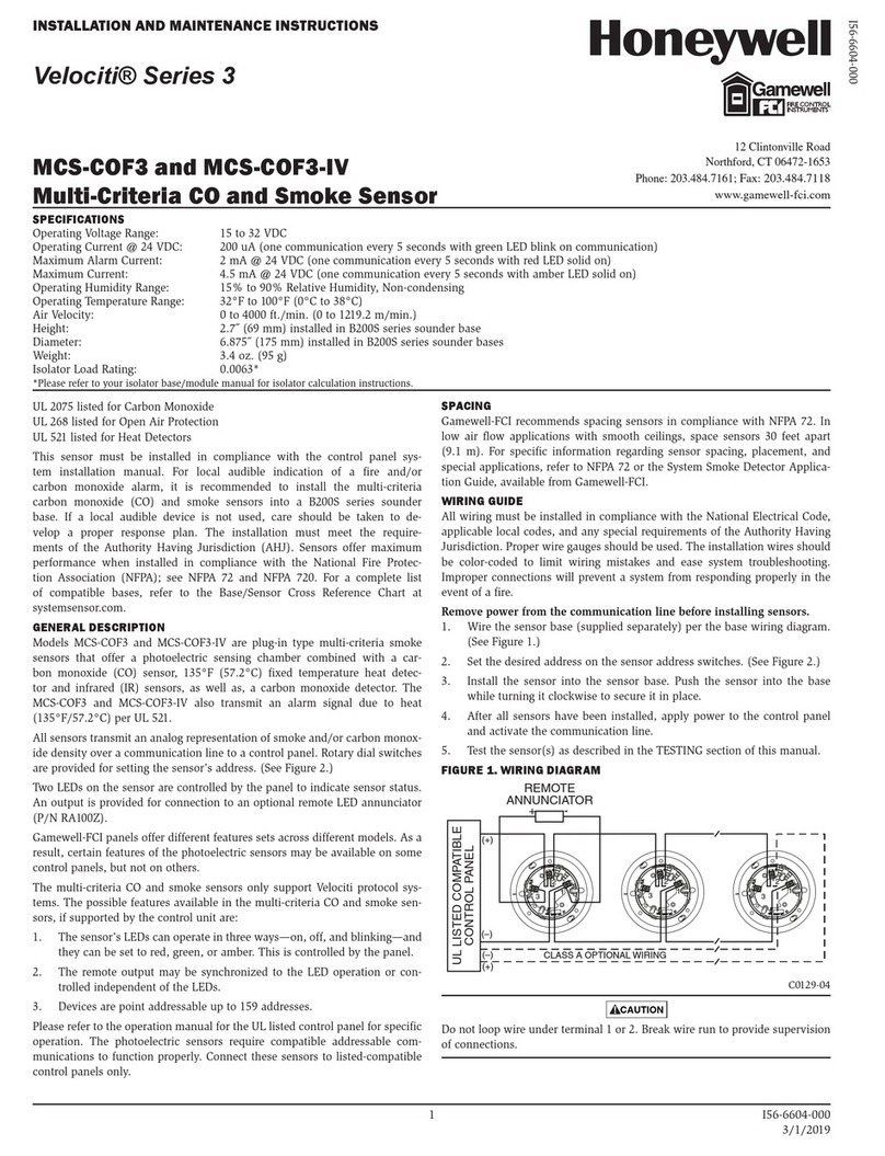
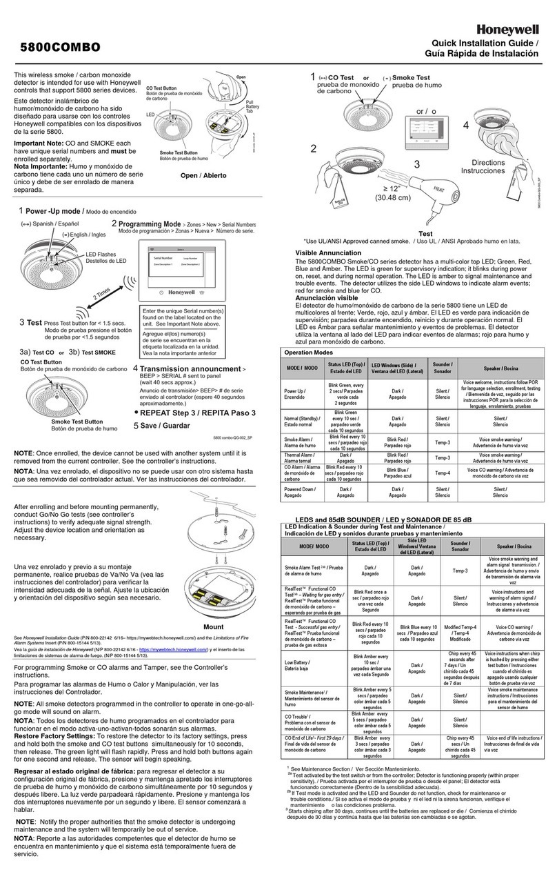
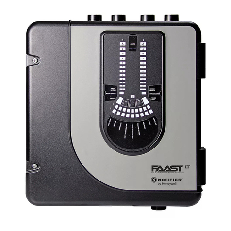
manuals.online logo
Brands
  1. Home
  2. •
  3. Brands
  4. •
  5. Honeywell
  6. •
  7. Smoke Alarm
  8. •
  9. Honeywell DFO800M User manual

Honeywell DFO800M User manual

Détecteur Optique de Fumée
Optical Smoke Detector
EKZ012100C: S1000-00-00 (I56-2623-002) 09-2005 - Page 1 – Honeywell - Sécurité Communications - Village d’entreprises - Bât D - Route des Dolines - BP41 - 06901 SOPHIA ANTIPOLIS CEDEX – France
Tél. : (33)492 942 950 - Fax : (33)492 942 960 - http://www.secom.tm.fr
Sécurité Communications se réserve le droit de modifier, à tout moment, dans l’intérêt du produit et/ou de l’utilisateur, ces caractéristiques techniques - Sécurité Communications reserve the right to change these technical specifications in the interest of product or user, without prior notice
D
DF
F
O
O
8
8
0
0
0
0M
M
Media Range
CR123A
x 1
Fournie / supplied
I
I
-
-
P
PR
RE
ES
SE
EN
NT
TA
AT
TI
IO
ON
N
Ce détecteur de fumée fait partie de la gamme de périphériques
radio « Média » associables à la centrale DOMONIAL 800 de
type CMI/CMT. Il est utilisé pour la détection d’incendie de
particules visibles.
Une LED rouge clignote une fois par seconde quand une alarme
est détectée et une fois toutes les 64 secondes en temps normal.
Le DFO800M emmettra une information spécifique en cas de
chambre de détection obstruée (information chambre sale).
I
II
I
-
-
M
MO
ON
NT
TA
AG
GE
E
Le détecteur doit être installé au centre de la surface à surveiller,
au plafond, dans les pièces où il y existe un risque d’incendie ou
d’asphyxie, comme les chambres ou le salon.
Etapes de montage :
1– Séparer la tête du détecteur de sa base en le tournant dans
le sens inverse des aiguilles d’une montre
2– Placer la base au plafond et marquer les points de fixations
3– Percer puis fixer la base à l’aide de 2 vis (maximum
4.0mm) en prenant soin de ne pas percer des tuyaux,
canalisation, câbles électriques…)
Prendre soin de protéger le détecteur de la poussière
durant cette opération.
4– Insérer la pile en respectant les polarités (image 1)
5– Le détecteur est maintenant prêt à être enregistré et la LED
clignote alors à une fréquence de 64 secondes
6– Mettre en place le détecteur dans sa base en faisant
coïncider les 2 repères (image 2) puis en le tournant dans le
sens des aiguilles d’une montre
I
II
II
I
–
–
P
PR
RO
OC
CE
ED
DU
UR
RE
E
D
DE
E
T
TE
ES
ST
T
Retirer, puis remettre le détecteur sur sa base pour tester la communication
avec la centrale. Un message radio est envoyé à la centrale à chaque
changement de status.
I
IV
V
–
–
A
AL
LI
IM
ME
EN
NT
TA
AT
TI
IO
ON
N
(
(p
pi
il
le
e
f
fo
ou
ur
rn
ni
ie
e)
)
Le détecteur signale un défaut pile à la centrale, lorsque sa tension
d’alimentation chute en dessous de 2,6V. (2,5V quand la température est
inférieure à 5°C). Il dispose d’une semaine d’autonomie après avoir signalé son
défaut pile.
ATTENTION : Il y a danger d'explosion s'il y a remplacement incorrect de
la pile. Remplacer uniquement avec une pile du même type ou d'un type
équivalent recommandé par le constructeur. Mettre au rebut les piles
usagées conformément aux instructions du fabricant.
V
V
-
-
E
EN
NR
RE
EG
GI
IS
ST
TR
RE
EM
ME
EN
NT
T
L'enregistrement est la procédure qui associe le détecteur à lacentrale. Cette
opération nécessite un outil de programmation fonctionnant sur PDA ou sur
PC. La procédure complète est décrite dans la notice de l’outil de
programmation.
1- Connecter l’outil de programmation et entrez en programmation
2- Choisir la rubrique « ENREGISTREMENT»
3– Déclencher l’autoprotection du périphérique en tournant le capot dans le
sens inverse des aiguilles d’une montre. Un message de confirmation
apparaît indiquant la prise en compte du détecteur par la centrale avec le
niveau radio et le numéro de série après quelques secondes
4– Choisir ensuite le mode de fonctionnement, le libellé…
5– Vous pouvez sortir du mode programmation
I
I
–
–
I
IN
NT
TR
RO
OD
DU
UC
CT
TI
IO
ON
N
This photoelectric smoke detector must be associated with the
DOMONIAL 800 ‘media’ range control panel (CMI/CMT). It will
detect and signal fires that give off visible combustion particles.
A red LED blinks once per second when smoke is detected, and
once every 64 seconds in normal mode.
The DFO800M will send a dedicated fault signal in the case of a dirty
detection chamber.
I
II
I
–
–
M
MO
OU
UN
NT
TI
IN
NG
G
The detector should be mounted on the ceiling, in rooms where there
is a risk of fire or asphyxia, such as bedrooms and living-rooms.
Mounting steps :
1– Separate the detector head from the base plate by turning it
anticlockwise.
2– Place the base on the ceiling and mark the two drilling points.
3– Drill (taking care to avoid ducts and pipes) and attach the base
with 2 screws, maximum diameter 4.0mm.
Take care to protect the detection chamber from dust during this
operation.
4– Insert the battery respecting the polarities: Note the “+” mark on
the circuit board (image 1).
5– The detector is now ready for registration and the red indicator
LED should blink once every 64 seconds.
6– Fit the detector to the mounting base by aligning the moulding
marks (image 2) and rotating it clockwise until it stops.
I
II
II
I
-
-
T
TE
ES
ST
T
P
PR
RO
OC
CE
ED
DU
UR
RE
E
Communications can be checked simply by removing the detector from the base
and replacing it. A radio message is sent at each status change.
I
IV
V
-
-
P
PO
OW
WE
ER
R
S
SU
UP
PP
PL
LY
Y
(
(b
ba
at
tt
te
er
ry
y
s
su
up
pp
pl
li
ie
ed
d)
)
The detector signals a battery fault to the control panel when the power supply
voltage drops below 2.6V (2.5V when the temperature drops below 5°C). The
detector oeprates for at least one week after indicating a battery fault.
WARNING : There is a risk of explosion in case of incorrect replacement of
the battery. Replace only with a battery of the same or equivalent type, which
has been recommended by the manufacturer. Throw away used batteries
according to the manufacturer’s instructions.
V
V
–
–
R
RE
EG
GI
IS
ST
TR
RA
AT
TI
IO
ON
N
Registration is the procedure that associates the detector with the control
panel. This operation requires a programming tool working on/compatible with
a PDA or a computer. The complete procedure is described in the
programming tool installation guide.
1– Connect the programming tool and start programming
2– Go to the ‘REGISTER’ menu
3– Generate a radio pulse by turning the cover anticlockwise, in order to activate
the tamper switch. The radio level and serial number appear after a few seconds
4– Choose the operating mode, the label, and so on.
5– Exit programming mode.
IMPORTANT : Le détecteur doit toujours être enregistré à son
emplacement définitif avec un minimum de réception de 2/10 IMPORTANT: The detector must always be programmed in its final
location with a minimum radio level of 2 units on a scale of 10
+ -
1
2
Détecteur Optique de Fumée
Optical Smoke Detector
EKZ012100C: S1000-00-00 (I56-2623-002) 09-2005 - Page 2 – Honeywell - Sécurité Communications - Village d’entreprises - Bât D - Route des Dolines - BP41 - 06901 SOPHIA ANTIPOLIS CEDEX – France
Tél. : (33)492 942 950 - Fax : (33)492 942 960 - http://www.secom.tm.fr
Sécurité Communications se réserve le droit de modifier, à tout moment, dans l’intérêt du produit et/ou de l’utilisateur, ces caractéristiques techniques - Sécurité Communications reserve the right to change these technical specifications in the interest of product or user, without prior notice
D
DF
F
O
O
8
8
0
0
0
0M
M
Media Range
CR123A
x 1
Fournie / supplied
V
VI
I
–
–E
EN
NT
TR
RE
ET
TI
IE
EN
N
1– Retirer le détecteur à nettoyer de sa base.
2– Oter avec précaution chacun des ergots amovibles qui maintiennent en place le
capot, puis retirer celui-ci.
3– Aspirer l’extérieur du filtre sans le retirer.
4– Oter le filtre qvec précaution de la chambre de détection. Si nécessaire, des filtres
de remplacement sont disponibles.
5– Utiliser l’aspirateur et/ou une soufflette (compresseur d’air) pour retirer la
poussière et le débris présents dans la chambre de détection ou à l’intérieur du filtre.
6– Remettre le filtre en place en alignant la flèche moulée sur celui-ci avec la flèche
présente sur la chambre de détection. Faire glisser le filtre sur la chambre et appliquer
une faible pression pour le bloquer en position.
7– Remettre le capot du détecteur. Aligner la LED avec ledit capot et clipser
l’ensemble en place en s’assurant que tous les ergots amovibles soient correctement
introduits. Fermer le détecteur.
8– Une fois tous les détecteurs nettoyés, effectuer un test comme indiqué en section
III, Procédure de Test.
V
VI
II
I
-
-
C
CA
AR
RA
AC
CT
TE
ER
RI
IS
ST
TI
IQ
QU
UE
ES
S
P
PR
RI
IN
NC
CI
IP
PA
AL
LE
ES
S
Techniques
Alimentation 1 pile lithium 3v type CR 123 A fournie
Autonomie 8 ans (typique)
Autoprotection Ouverture
Signalisation 1 LED
Gestion du défaut pile Oui
Gestion du défaut chambre sale Oui
Température de fonctionnement -5° à 55°C (23° à 131°F)
Température de stockage -20° à +60°C. (-4° à 140°F)
Dimensions 45 mm (h), 102 mm (diamètre)
Poids 130g (avec pile).
Couleur Blanc
Radio
Type FM bande étroite :
Fréquence 868,75 MHz
Portée radio 50m sur site
Supervision Oui
Détection
Type Optique de fumée
Rayon d’action Environ 100m2
Période de nettoyage Tous les 4 ans (typique)
V
VI
I
–
–
M
MA
AI
IN
NT
TE
EN
NA
AN
NC
CE
E
1– Remove the detector to be cleaned from its base.
2– Carefully separate the lugs securing the cover assembly, and remove the unit.
3– Without removing the filter, use a vacuum cleaner to clean this from the outside.
4– Carefully remove the filter from the detection chamber by pulling gently. If
necessary, replacement filters are available.
5– Use the vacuum cleaner or an air compressor to remove the dust and debris from
the detection chamber or the inside of the filter.
6– Replace the filter by aligning the arrow on the filter with that of the detection
chamber, sliding the filter onto the chamber and pressing gently.
7– Replace the detection chamber in the cover by aligning the LED on the chamber
with the hole in the cover, and pressing until the lugs click into position. Replace the
cover.
8– When all the detectors have been cleaned, carry out the test procedure, as
described in section III, Test Procedure.
V
VI
II
I
–
–
M
MA
AI
IN
N
C
CH
HA
AR
RA
AC
CT
TE
ER
RI
IS
ST
TI
IC
CS
S
Technical
Power supply one 3v CR123 A lithium battery (supplied)
Battery life Typically 8 years
Tamper Removal from mounting base
Signalling 1 LED
Low battery reported Yes
Dirty Chamber reported Yes
Operating temperature -5° to 55°C (23° to 131°F)
Storage temperature -20° to +60°C (-4° to +140°F)
Dimensions 45 mm (h), 102 mm (diameter)
Weight 130g (including battery)
Colour White
Radio
Type FM narrow band
Frequency 868.75 MHz
Radio range 50m on site
Supervision Yes
Detection
Type Photoelectric (Optical)
Covereage Area Approximately 100m2
Cleaning Interval Typically 4 years
Description du défaut / Fault description
N° de série de l’appareil / serial number Cause du retour / cause of return Défaut constaté / noticed fault
Installateur / Installer
Effraction
-
--
--
--
--
--
--
-
Intrusion
A
l’installation
-
--
--
--
--
--
-
During installation
-
--
--
-
date
Rénovation ---- Cosmetic repair Sur intervention --- On intervention ------ date
Panne ----------- Fault
Défaut aléatoire ----
Random fault
A compléter et à joindre au produit lors de son retour en SAV. Tout
produit retourné sans cette fiche entraînera son diagnostic complet
et, en conséquence, une facturation forfaitaire pour la prestation de
remise en état.
To fill in and return together with the faulty product. Any reception without
« Repair Sheet » attached to the equipment will result in a full process
diagnosis, repair and test. A fixed price repair would consequently apply.
F
FI
IC
CH
HE
E
D
DE
E
R
RE
ET
TO
OU
UR
R
S
SA
AV
V
–
–
R
R
E
E
P
P
A
A
I
I
R
R
S
S
H
H
E
E
E
E
T
T

Other Honeywell Smoke Alarm manuals

Honeywell Xtralis FAAST FLEX FLX-010 User manual

Honeywell

Honeywell Xtralis FAAST FLEX FLX-010 User manual

Honeywell Lyric User manual

Honeywell

Honeywell Lyric User manual

Honeywell FMST FXV(E) Series User manual

Honeywell

Honeywell FMST FXV(E) Series User manual

Honeywell Gamewell 7100 Series Installation instructions

Honeywell

Honeywell Gamewell 7100 Series Installation instructions

Honeywell ALL-SPEC User manual

Honeywell

Honeywell ALL-SPEC User manual

Honeywell Fire-Lite Alarms OSI-RI-FL User manual

Honeywell

Honeywell Fire-Lite Alarms OSI-RI-FL User manual

Honeywell SS4-AS User manual

Honeywell

Honeywell SS4-AS User manual

Honeywell Notifier VESDA-E VEA Series User manual

Honeywell

Honeywell Notifier VESDA-E VEA Series User manual

Honeywell FAAST LT User manual

Honeywell

Honeywell FAAST LT User manual

Honeywell Velociti 3 Series User manual

Honeywell

Honeywell Velociti 3 Series User manual

Honeywell C8600A User manual

Honeywell

Honeywell C8600A User manual

Honeywell GENT Venturi-Air Duct Kit User manual

Honeywell

Honeywell GENT Venturi-Air Duct Kit User manual

Honeywell DF8M User manual

Honeywell

Honeywell DF8M User manual

Honeywell HI-SPEC User manual

Honeywell

Honeywell HI-SPEC User manual

Honeywell MORLEY-IAS MI-LPB2-S2I User manual

Honeywell

Honeywell MORLEY-IAS MI-LPB2-S2I User manual

Honeywell TC842B1007AE User manual

Honeywell

Honeywell TC842B1007AE User manual

Honeywell Smoke Alarm User manual

Honeywell

Honeywell Smoke Alarm User manual

Honeywell SS4-AI User manual

Honeywell

Honeywell SS4-AI User manual

Honeywell 5800COMBO User manual

Honeywell

Honeywell 5800COMBO User manual

Honeywell GasAlertMicro 5 User manual

Honeywell

Honeywell GasAlertMicro 5 User manual

Honeywell XLS-278 User manual

Honeywell

Honeywell XLS-278 User manual

Honeywell 5193SD User manual

Honeywell

Honeywell 5193SD User manual

Honeywell NOTIFIER NFXI-ASD11 Quick start guide

Honeywell

Honeywell NOTIFIER NFXI-ASD11 Quick start guide

Honeywell Gamewell Velociti 3 Series User manual

Honeywell

Honeywell Gamewell Velociti 3 Series User manual

Popular Smoke Alarm manuals by other brands

Pyromate P-45 manual

Pyromate

Pyromate P-45 manual

System Sensor OSI-RE-SS Installation and maintenance instructions

System Sensor

System Sensor OSI-RE-SS Installation and maintenance instructions

Notifier SD-651A Installation and maintenance instructions

Notifier

Notifier SD-651A Installation and maintenance instructions

Elkron SD610 Installation, programming and functions manual

Elkron

Elkron SD610 Installation, programming and functions manual

Firehawk Fast-Fix user manual

Firehawk

Firehawk Fast-Fix user manual

detectomat HDv 300 OS Series Operation and installation manual

detectomat

detectomat HDv 300 OS Series Operation and installation manual

Universal SS-785 instructions

Universal

Universal SS-785 instructions

x-sense XS01-WR user manual

x-sense

x-sense XS01-WR user manual

Firehawk FHB10W manual

Firehawk

Firehawk FHB10W manual

A-Collection KD-122LA installation instructions

A-Collection

A-Collection KD-122LA installation instructions

FIBARO FIB_FGSS-101 quick start

FIBARO

FIBARO FIB_FGSS-101 quick start

Mobeye CM2410 user manual

Mobeye

Mobeye CM2410 user manual

NOXE LUMENS Installation and user guide

NOXE

NOXE LUMENS Installation and user guide

DSW DSW98A user manual

DSW

DSW DSW98A user manual

Kidde DC-9102E-KID quick start guide

Kidde

Kidde DC-9102E-KID quick start guide

Universal Security Instruments MPI305 instructions

Universal Security Instruments

Universal Security Instruments MPI305 instructions

DSC Meridian WLS906 Instructions for installation and use

DSC

DSC Meridian WLS906 Instructions for installation and use

Lexing LX108A instructions

Lexing

Lexing LX108A instructions

manuals.online logo
manuals.online logoBrands
  • About & Mission
  • Contact us
  • Privacy Policy
  • Terms and Conditions

Copyright 2025 Manuals.Online. All Rights Reserved.